Download as PDF, PPTX
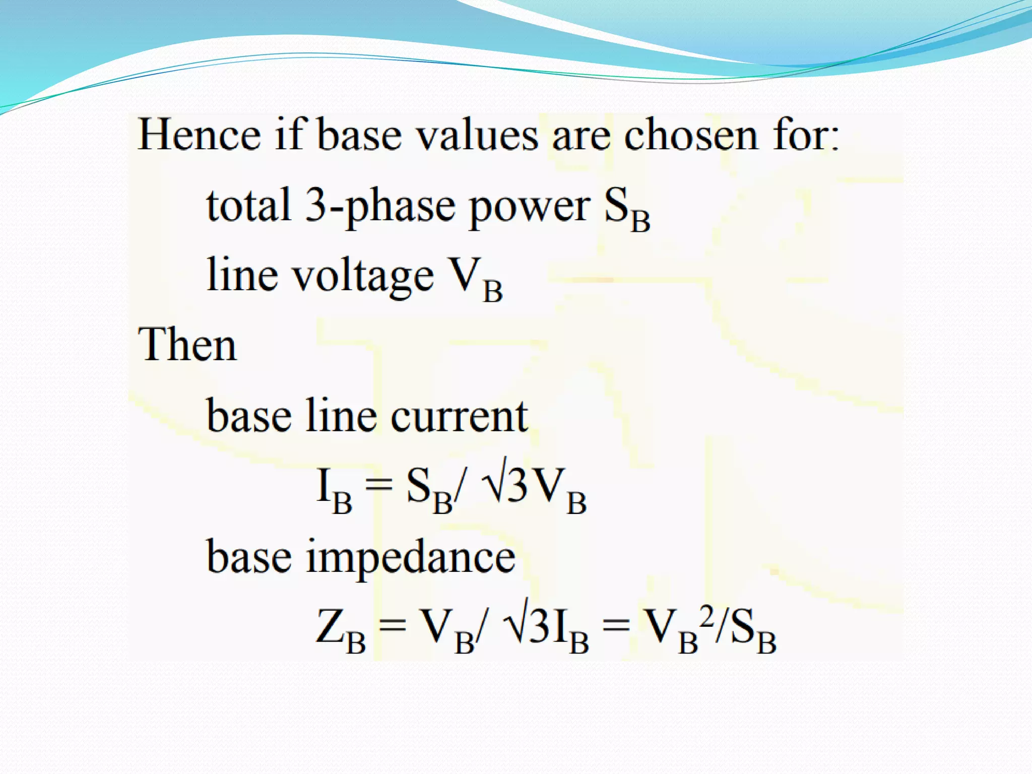
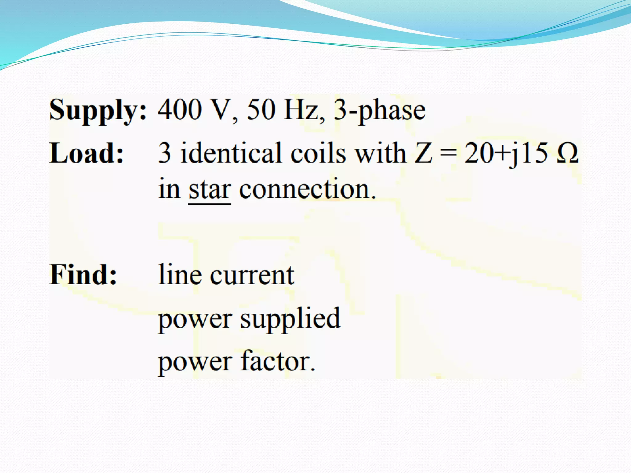
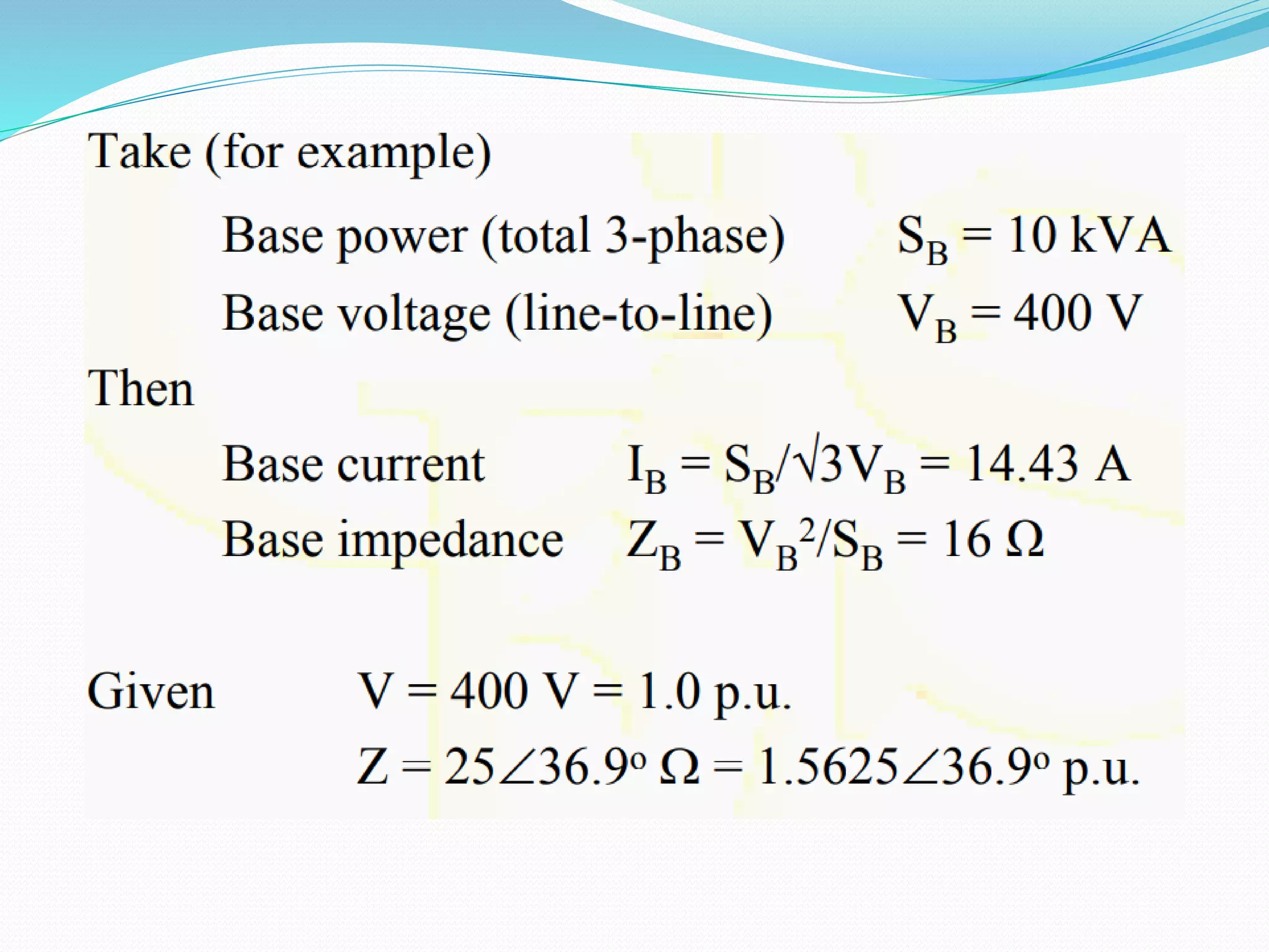
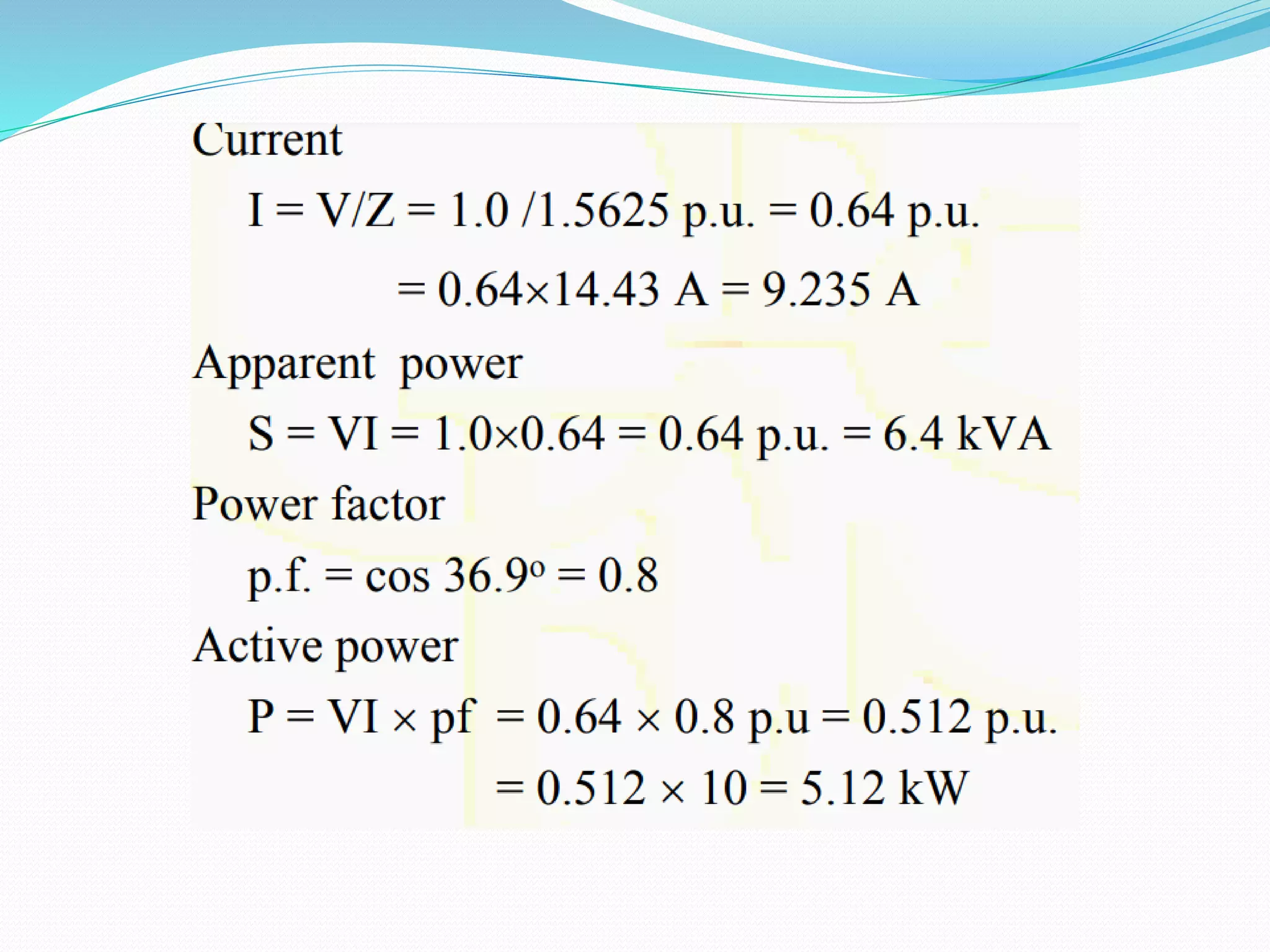
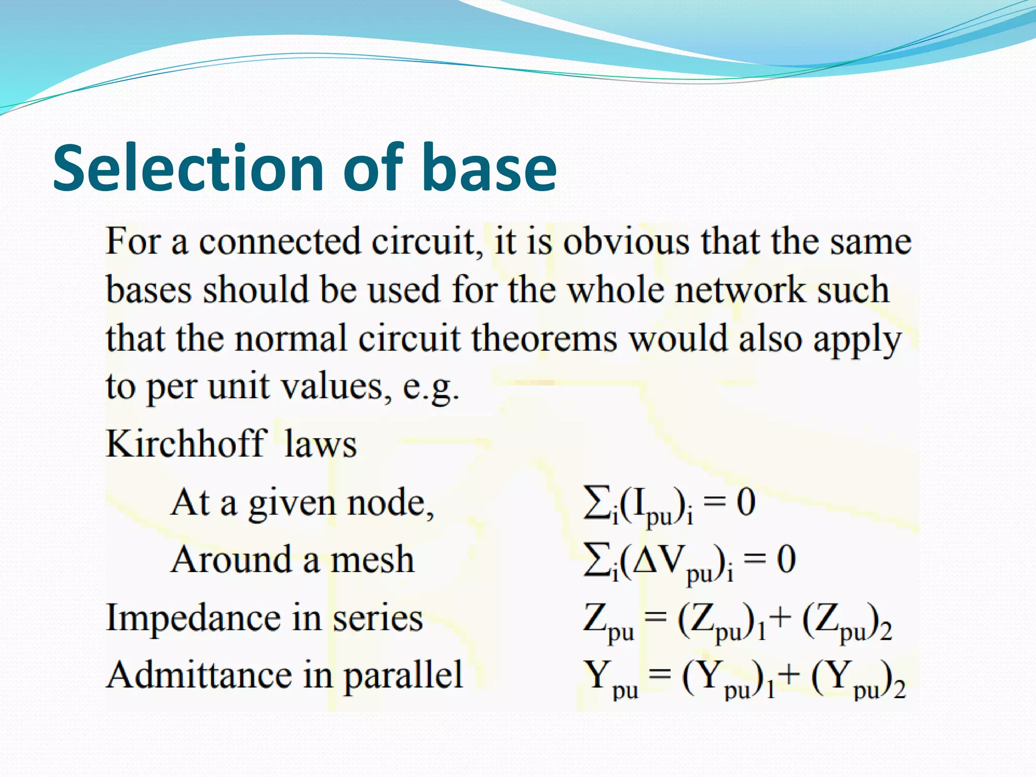
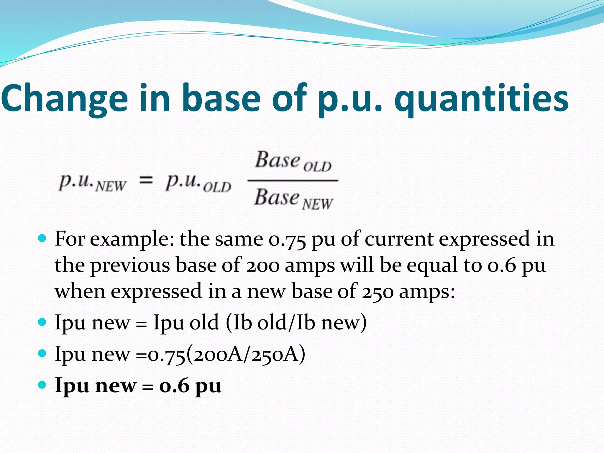
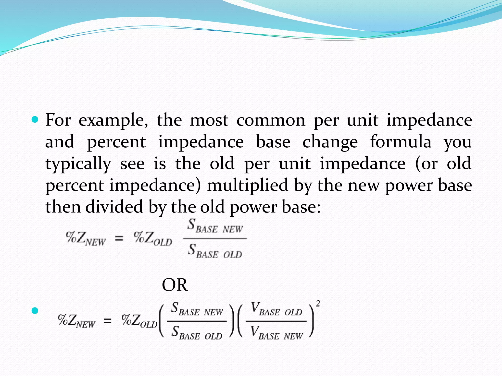
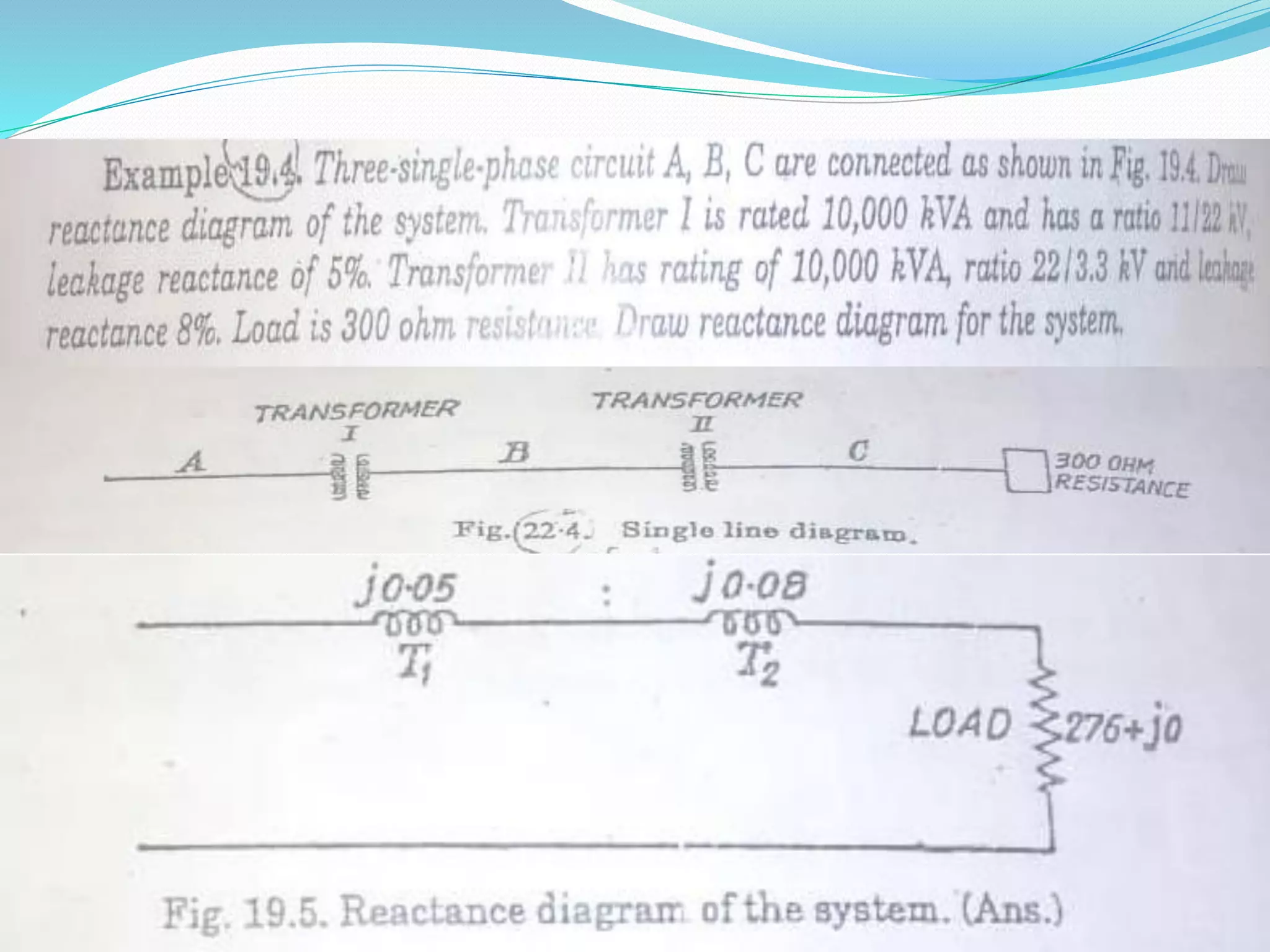
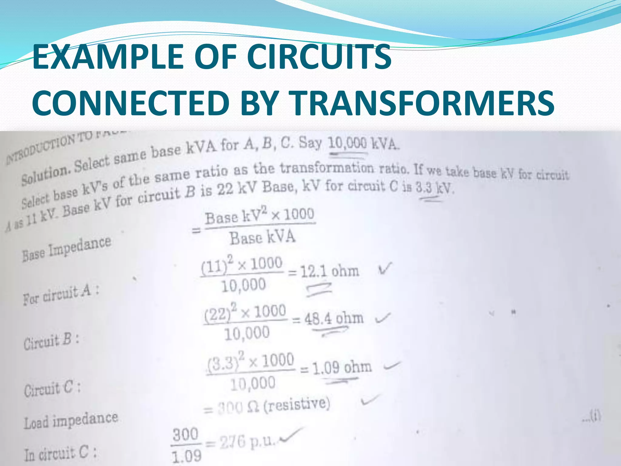
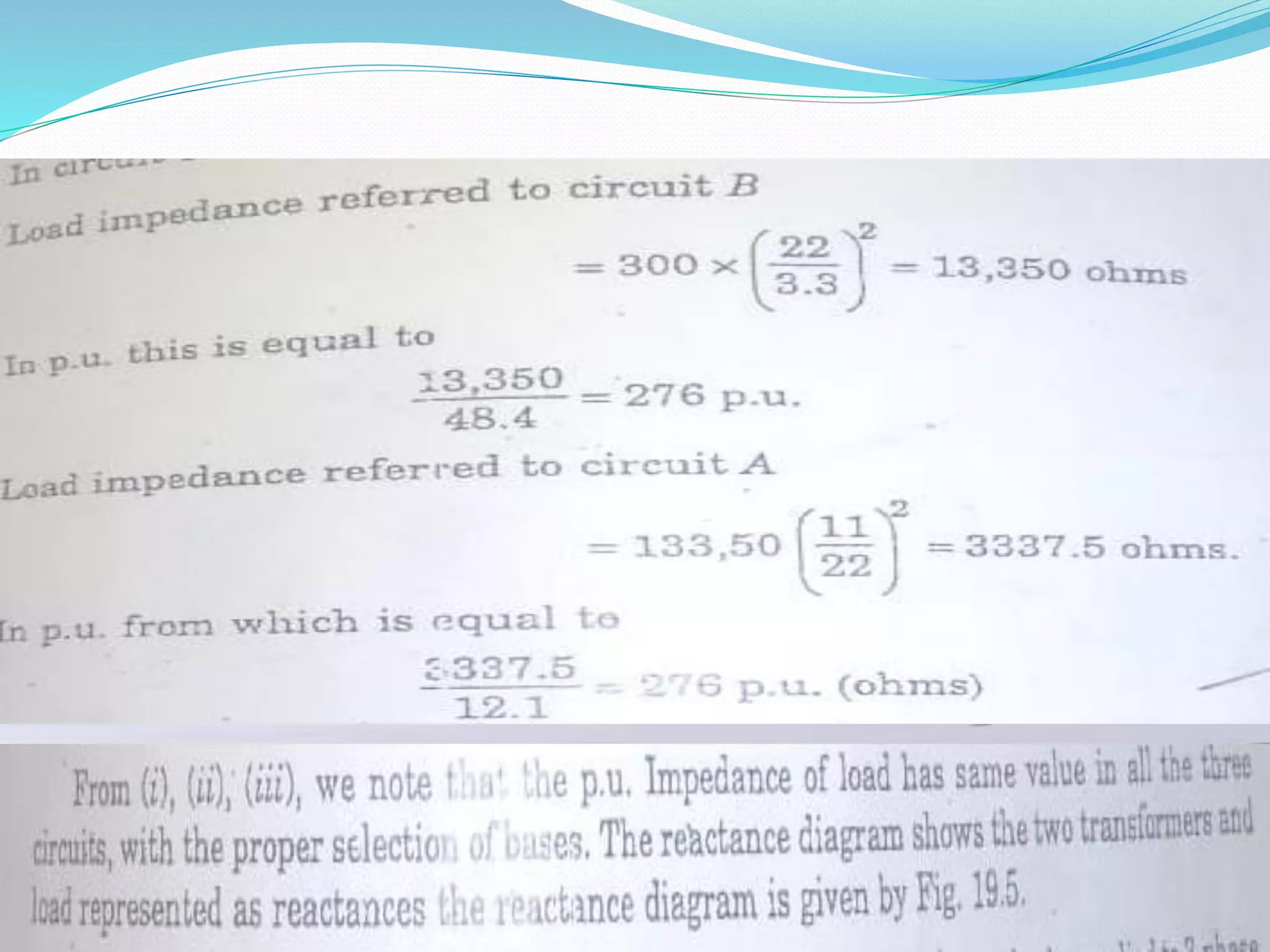


The document covers an introductory course on power system analysis, focusing on circuit constants, power system representation, fault analysis, and stability. Key topics include one-line diagrams, impedance and reactance diagrams, per-unit quantities, and the selection of base values for calculations. It also explains examples of transformer connections and presents formulas for per-unit impedance calculations.