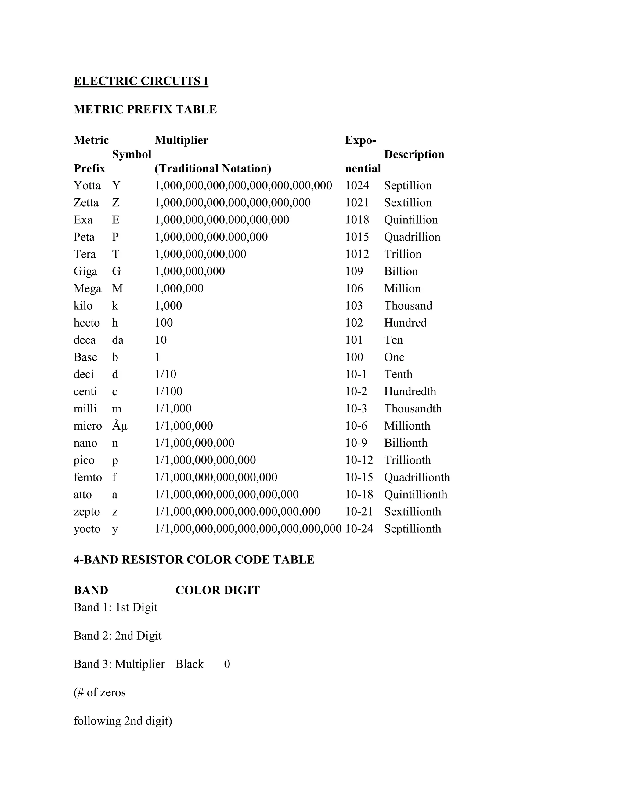
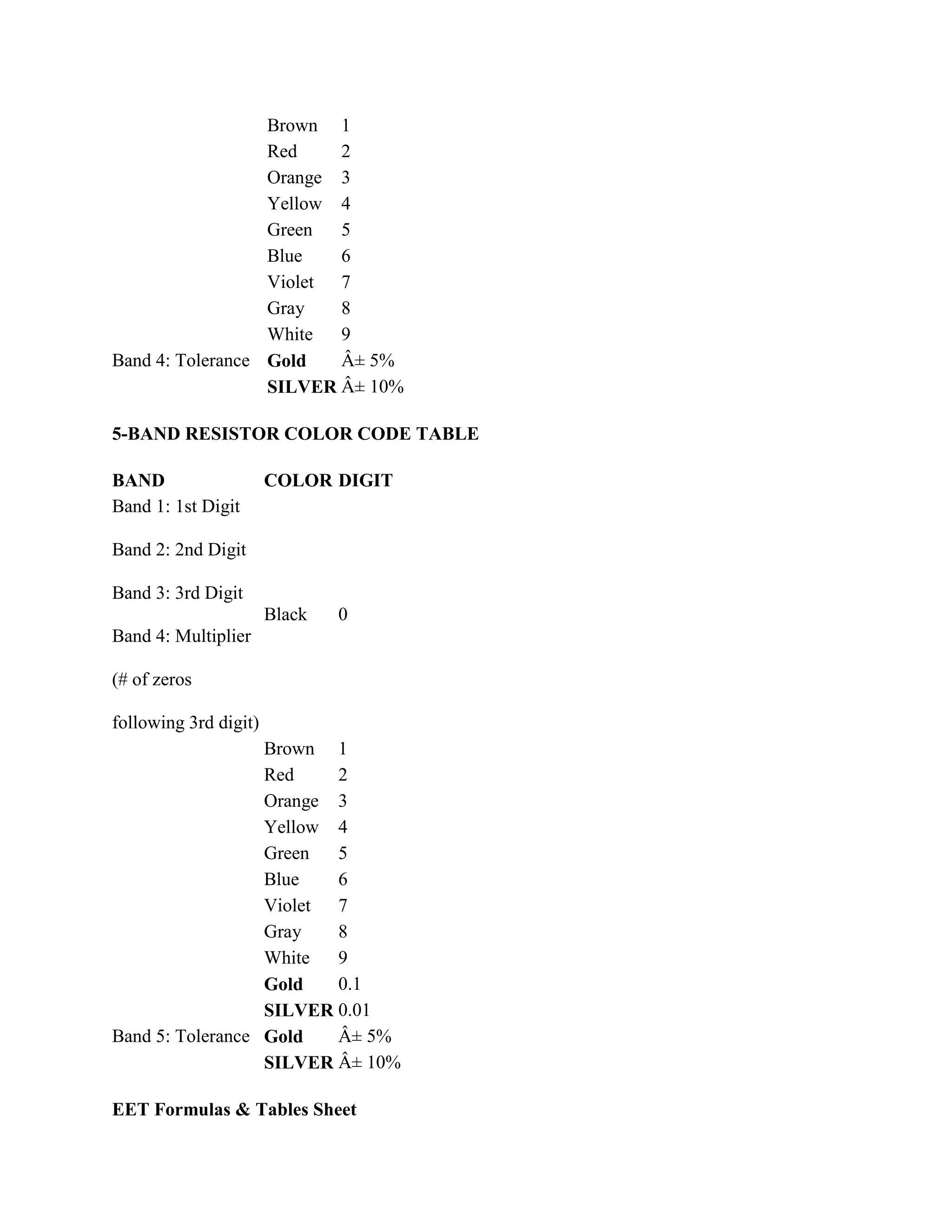
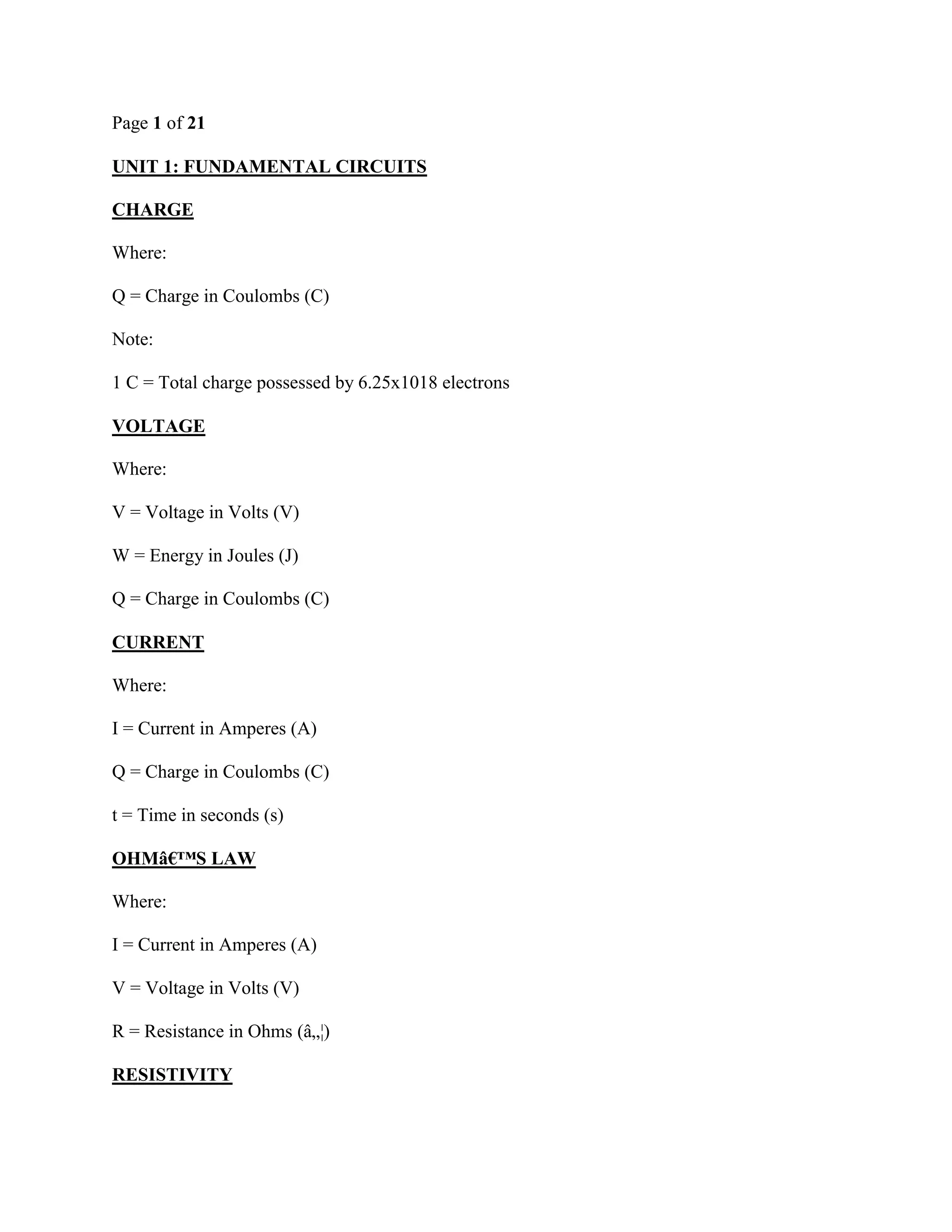
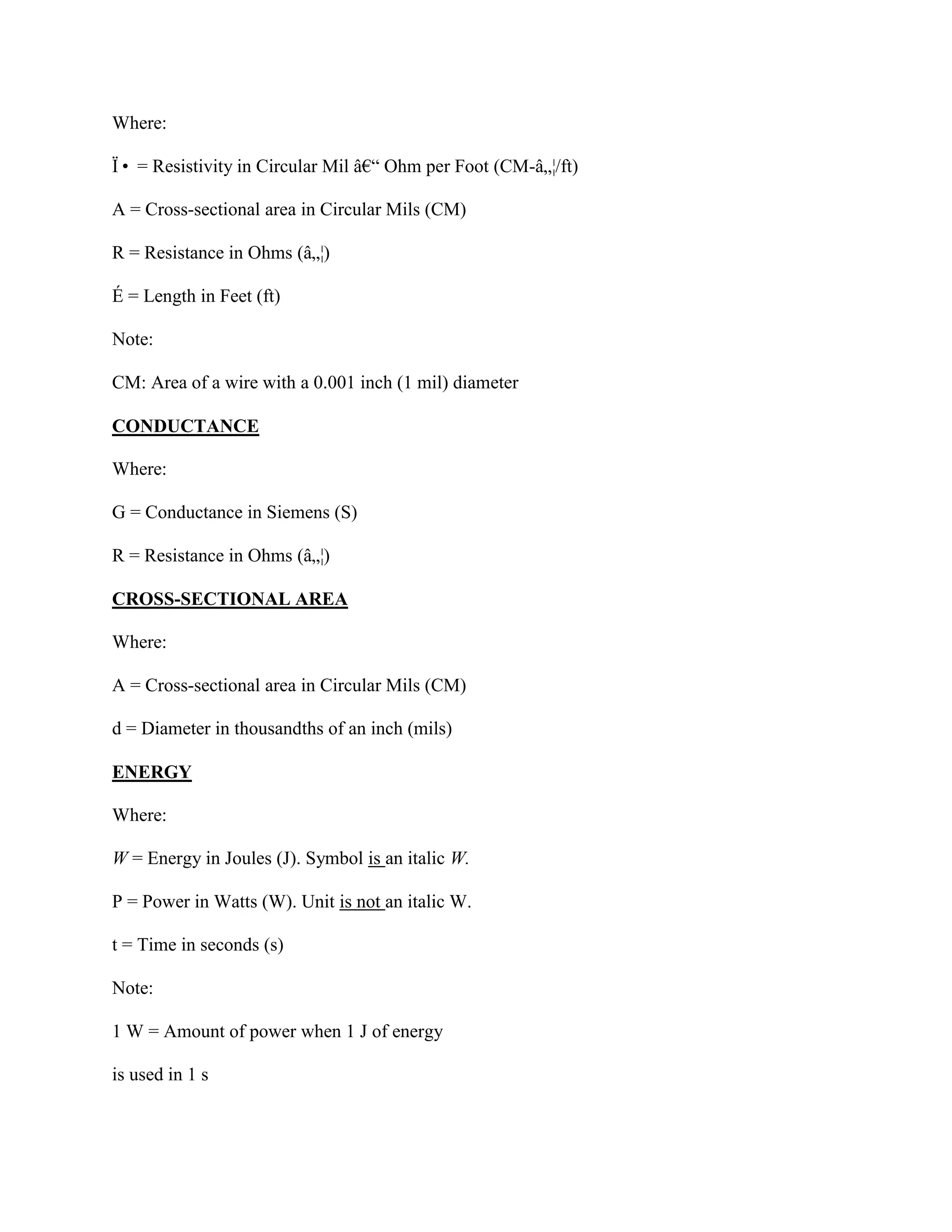
SlideShare a Scribd company logo
ELECTRIC CIRCUITS I
METRIC PREFIX TABLE
Metric
Prefix
Symbol
Multiplier
(Traditional Notation)
Expo-
nential
Description
Yotta Y 1,000,000,000,000,000,000,000,000 1024 Septillion
Zetta Z 1,000,000,000,000,000,000,000 1021 Sextillion
Exa E 1,000,000,000,000,000,000 1018 Quintillion
Peta P 1,000,000,000,000,000 1015 Quadrillion
Tera T 1,000,000,000,000 1012 Trillion
Giga G 1,000,000,000 109 Billion
Mega M 1,000,000 106 Million
kilo k 1,000 103 Thousand
hecto h 100 102 Hundred
deca da 10 101 Ten
Base b 1 100 One
deci d 1/10 10-1 Tenth
centi c 1/100 10-2 Hundredth
milli m 1/1,000 10-3 Thousandth
micro µ 1/1,000,000 10-6 Millionth
nano n 1/1,000,000,000 10-9 Billionth
pico p 1/1,000,000,000,000 10-12 Trillionth
femto f 1/1,000,000,000,000,000 10-15 Quadrillionth
atto a 1/1,000,000,000,000,000,000 10-18 Quintillionth
zepto z 1/1,000,000,000,000,000,000,000 10-21 Sextillionth
yocto y 1/1,000,000,000,000,000,000,000,000 10-24 Septillionth
4-BAND RESISTOR COLOR CODE TABLE
BAND COLOR DIGIT
Band 1: 1st Digit
Band 2: 2nd Digit
Band 3: Multiplier
(# of zeros
following 2nd digit)
Black 0
Brown 1
Red 2
Orange 3
Yellow 4
Green 5
Blue 6
Violet 7
Gray 8
White 9
Band 4: Tolerance Gold ± 5%
SILVER ± 10%
5-BAND RESISTOR COLOR CODE TABLE
BAND COLOR DIGIT
Band 1: 1st Digit
Band 2: 2nd Digit
Band 3: 3rd Digit
Band 4: Multiplier
(# of zeros
following 3rd digit)
Black 0
Brown 1
Red 2
Orange 3
Yellow 4
Green 5
Blue 6
Violet 7
Gray 8
White 9
Gold 0.1
SILVER 0.01
Band 5: Tolerance Gold ± 5%
SILVER ± 10%
EET Formulas & Tables Sheet
Page 1 of 21
UNIT 1: FUNDAMENTAL CIRCUITS
CHARGE
Where:
Q = Charge in Coulombs (C)
Note:
1 C = Total charge possessed by 6.25x10¹⁸ electrons
VOLTAGE
Where:
V = Voltage in Volts (V)
W = Energy in Joules (J)
Q = Charge in Coulombs (C)
CURRENT
Where:
I = Current in Amperes (A)
Q = Charge in Coulombs (C)
t = Time in seconds (s)
OHM’S LAW
Where:
I = Current in Amperes (A)
V = Voltage in Volts (V)
R = Resistance in Ohms (Ω)
RESISTIVITY
Where:
ϕ = Resistivity in Circular Mil – Ohm per Foot (CM-Ω/ft)
A = Cross-sectional area in Circular Mils (CM)
R = Resistance in Ohms (Ω)
É = Length in Feet (ft)
Note:
CM: Area of a wire with a 0.001 inch (1 mil) diameter
CONDUCTANCE
Where:
G = Conductance in Siemens (S)
R = Resistance in Ohms (Ω)
CROSS-SECTIONAL AREA
Where:
A = Cross-sectional area in Circular Mils (CM)
d = Diameter in thousandths of an inch (mils)
ENERGY
Where:
W = Energy in Joules (J). Symbol is an italic W.
P = Power in Watts (W). Unit is not an italic W.
t = Time in seconds (s)
Note:
1 W = Amount of power when 1 J of energy
is used in 1 s
POWER
Where:
P = Power in Watts (W)
V = Voltage in Volts (V)
I = Current in Amperes (A)
Note:
Ptrue = P in a resistor is also called true power
OUTPUT POWER
Where:
POUT = Output power in Watts (W)
PIN = Input power in Watts (W)
PLOSS = Power loss in Watts (W)
POWER SUPPLY EFFICIENCY
Where:
POUT = Output power in Watts (W)
PIN = Input power in Watts (W)
Efficiency = Unitless value
Note:
Efficiency expressed as a percentage:
UNIT 2: SERIES CIRCUITS (R1, R2, , Rn)
TOTAL RESISTANCE
Where:
RT = Total series resistance in Ohms (Ω)
Rn = Circuit’s last resistor in Ohms (Ω)
KIRCHHOFF’S VOLTAGE LAW
Where:
VS = Voltage source in Volts (V)
Vn = Circuit’s last voltage drop in Volts (V)
VOLTAGE – DIVIDER
Where:
Vx = Voltage drop in Ohms (Ω)
Rx = Resistance where Vx occurs in Ohms (Ω)
RT = Total series resistance in Ohms (Ω)
VS = Voltage source in Volts (V) TOTAL POWER
Where:
PT = Total power in Watts (W)
Pn = Circuit’s last resistor’s power in Watts (W)
UNIT 3: PARALLEL CIRCUITS (R1||R2||||Rn)
TOTAL RESISTANCE
Where:
RT = Total parallel resistance in Ohms (Ω)
Rn = Circuit’s last resistor in Ohms (Ω)
TOTAL RESISTANCE - TWO RESISTORS IN PARALLEL
Where:
RT = Total parallel resistance in Ohms (Ω)
TOTAL RESISTANCE - EQUAL-VALUE RESISTORS
Where:
RT = Total parallel resistance in Ohms (Ω)
R = Resistor Value in Ohms (Ω)
n = Number of equal value resistors (Unitless)
UNKNOWN RESISTOR
Where:
Rx = Unknown resistance in Ohms (Ω)
RA = Known parallel resistance in Ohms (Ω)
RT = Total parallel resistance in Ohms (Ω)
KIRCHHOFF’S CURRENT LAW
Where:
n = Number of currents into node (Unitless)
m = Number of currents going out of node (Unitless)
CURRENT – DIVIDER
Where:
Ix = Branch “x― current in Amperes (A)
RT = Total parallel resistance in Ohms (Ω)
Rx = Branch “x” resistance in Ohms (Ω)
IT = Total current in Amperes (A)
TWO-BRANCH CURRENT – DIVIDER
Where:
I1 = Branch “1― current in Amperes (A)
R2 = Branch “2” resistance in Ohms (Ω)
R1 = Branch “1” resistance in Ohms (Ω)
IT = Total current in Amperes (A)
TOTAL POWER
Where:
PT = Total power in Watts (W)
Pn = Circuit’s last resistor’s power in Watts (W)
OPEN BRANCH RESISTANCE
Where:
ROpen = Resistance of open branch in Ohms (Ω)
RT(Meas) = Measured resistance in Ohms (Ω)
GT(Calc) = Calculated total conductance in Siemens (S)
GT(Meas) = Measured total conductance in Siemens (S)
Note:
GT(Meas) obtained by measuring total resistance, RT(Meas)
UNIT 4: SERIES - PARALLEL CIRCUITS
BLEEDER CURRENT
Where:
IBLEEDER = Bleeder current in Amperes (A)
IT = Total current in Amperes (A)
IRL1 = Load resistor 1 current in Amperes (A)
IRL2 = Load resistor 2 current in Amperes (A)
THERMISTOR BRIDGE OUTPUT
Where:
= Change in output voltage in Volts (V)
= Change in thermal resistance in Ohms (Ω)
VS = Voltage source in Volts (V)
R = Resistance value in Ohms (Ω)
UNKNOWN RESISTANCE IN A WHEATSTONE BRIDGE
Where:
RX = Unknown resistance in Ohms (Ω)
RV = Variable resistance in Ohms (Ω)
R2 = Resistance 2 in Ohms (Ω)
R4 = Resistance 4 in Ohms (Ω)
UNIT 5: MAGNETISM AND ELECTROMAGNETISM
MAGNETIC FLUX DENSITY
Where:
B = Magnetic flux density in Tesla (T)
= Flux in Weber (Wb)
(Greek letter Phi)
A = Cross-sectional area in square meters (m2)
Note:
Tesla (T) equals a Weber per square meter (Wb/m2)
RELATIVE PERMEABILITY
Where:
= Relative permeability (Unitless)
(Greek letter Mu)
= Permeability in Webers per Ampere-turn · meter
(Wb/At·m)
= Vacuum permeability in Webers per Ampere-
turn · meter (Wb/At·m)
Note:
= Wb/ At·m
RELUCTANCE
Where:
R = Reluctance in Ampere-turn per Weber (At/Wb)
É = Length of magnetic path in meters (m)
µ = Permeability in Weber per Ampere-turn · meter
(Wb/At · m)
A = Cross-sectional area in meters squares (m2)
MAGNETOMOTIVE FORCE
Where:
Fm = Magnetomotive force (mmf) in Ampere-turn (At)
N = Number of Turns of wire (t)
I = Current in Amperes (A)
MAGNETIC FLUX
Where:
= Flux in Weber (Wb)
Fm = Magnetomotive force in Ampere-turn (At)
R = Reluctance in Ampere-turn per Weber (At/Wb)
MAGNETIC FIELD INTENSITY
Where:
H = Magnetic field intensity in Amperes-turn per
meter (At/m)
Fm = Magnetomotive force in Ampere-turn (At)
É = Length of material in meters (m)
INDUCED VOLTAGE
Where:
vind = Induced voltage in Volts (V)
B = Magnetic flux density in Tesla (T)
É = Length of the conductor exposed to the magnetic
field in meters (m)
v = Relative velocity in meters per second (m/s)
Note:
Tesla (T) equals a Weber per square meter (Wb/m2)
FARADAY’S LAW
Where:
vind = Induced voltage in Volts (V)
N = Number of turns of wire in the coil (Unitless)
= Rate of change of magnetic field with respect
to the coil in Webers per second (Wb/s)
ELECTRIC CIRCUITS II
UNIT 1: ALTERNATE CURRENT & INDUCTORS
ALTERNATE CURRENT
FREQUENCY & PERIOD
Where:
f = Frequency in Hertz (Hz)
T = Period in Seconds (s)
Note:
1 Hertz = 1 cycle per 1 second
PEAK TO PEAK VOLTAGE
Where:
Vpp = Peak to peak voltage in Volts (V)
Vp = Peak voltage in Volts (V)
ROOT MEAN SQUARE (RMS) VOLTAGE
Where:
Vrms = Root mean square voltage in Volts (V)
Vp = Peak voltage in Volts (V)
HALF-CYCLE AVERAGE VOLTAGE
Where:
Vavg = Half-cycle average voltage in Volts (V)
Vp = Peak voltage in Volts (V)
RADIAN & DEGREE CONVERSION
Where:
Rad = Number of radians in Rad (rad)
Degrees = Number of degrees in Degrees (0)
Note:
= 3.1416 (Greek letter Pi)
GENERATOR OUTPUT FREQUENCY
Where:
f = Frequency in Hertz (Hz)
Number of pole pairs = Number of pole pairs (Unitless)
rps = Revolutions per second in Revolutions per
Second (rps)
PEAK TO PEAK CURRENT
Where:
Ipp = Peak to peak current in Amperes (A)
Ip = Peak current in Amperes (A)
ROOT MEAN SQUARE (RMS) CURRENT
Where:
Irms = Root mean square current in Amperes (A)
Ip = Peak current in Amperes (A)
HALF-CYCLE AVERAGE CURRENT
Where:
Iavg = Half-cycle average current in Amperes (A)
Ip = Peak current in Amperes (A)
SINE WAVE GENERAL FORMULA
Where:
y = Instantaneous voltage or current value
at angle in Volts or Amperes (V or A)
(Greek letter Theta)
A = Maximum voltage or current value in Volts or
Amperes (V or A)
= Angle where given instantaneous voltage or
current value exists
SINE WAVE LAGGING THE REFERENCE
Where:
y = Instantaneous voltage or current value
at angle in Volts or Amperes (V or A)
A = Maximum voltage or current value in Volts or
Amperes (V or A)
= Angle where given instantaneous voltage or
current value exists
= Angle sine wave is shifted right (lagging) of
reference (Greek letter Phi)
ANGULAR VELOCITY
Where:
= Angular velocity in Radians per second (rad/s)
(Small Greek letter omega)
f = Frequency in Hertz (Hz)
Note:
= 3.1416
SINE WAVE VOLTAGE
Where:
v = Sinusoidal voltage in Volts (V)
Vp = Peak voltage in Volts (V)
f = Frequency in Hertz (Hz)
t = Time in Seconds (s)
Note:
= 3.1416
PULSE WAVEFORM AVERAGE VALUE
Where:
vavg = Pulse waveform average value in Volts (V)
baseline = Baseline in Volts (V)
duty cycle = Percent duty cycle in Percent/100%
(Unitless)
Amplitude = Amplitude in Volts (V)
SINE WAVE LEADING THE REFERENCE
Where:
y = Instantaneous voltage or current value
at angle in Volts or Amperes (V or A)
A = Maximum voltage or current value in Volts or
Amperes (V or A)
= Angle where given instantaneous voltage or
current value exists
= Angle sine wave is shifted left (leading) of
reference
PHASE ANGLE
Where:
= Angle sine wave is shifted in Radians (rad)
= Angular velocity in Radians per second (rad/s)
t = Time in Seconds (s)
DUTY CYCLE
Where:
Percent duty cycle = Percent duty cycle in Percentage (%)
tw = Pulse width in Seconds (s)
T = Period in Seconds (s)
F = Frequency in Hertz (Hz)
INDUCTORS
INDUCED VOLTAGE
Where:
vind = Induced voltage in Volts (V)
L = Inductance in Henries (H)
= Time rate of change of the current in Amperes
per second (A/s)
INDUCTANCE OF A COIL
Where:
L = Inductance of a coil in Henries (H)
N = Number of turns of wire (Unitless)
= Permeability in Henries per meter (H/m)
A = Cross-sectional area in Meters squared (m2)
= Core length in Meters (m)
Notes:
Permeability in H/m is equal to Wb/At·m
Non-magnetic core = Permeability of a vacuum, µ0
µ0 = 4 x 10⁻⁷ H/m
RL TIME CONSTANT
Where:
= RL time constant in Seconds (s) (Greek letter Tau)
L = Inductance in Henries (H)
R = Resistance in Ohms (Ω)
GENERAL EXPONENTIAL VOLTAGE FORMULA
Where:
v = Instantaneous voltage at time, t, in Volts (V)
VF = Voltage final value in Volts (V)
Vi = Voltage initial value in Volts (V)
R = Resistance in Ohms (Ω)
t = Time in Seconds (s)
L = Inductance in Henries (H)
INDUCTOR ENERGY STORAGE
Where:
W = Energy in Joules (J)
L = Inductance in Henries (H)
I = Current in Amperes (A)
TOTAL INDUCTANCE - SERIES
Where:
LT = Total series inductance in Henries (H)
Ln = Circuit’s last inductor in Henries (H)
TOTAL INDUCTANCE – PARALLEL
Where:
LT = Total parallel inductance in Henries (H)
Ln = Circuit’s last inductor in Henries (H)
RL CIRCUIT CURRENT INCREASE AND DECREASE
FOR GIVEN NUMBER OF TIME CONSTANTS
# of Time Constants Approx % of Final Current Approx % of Initial Charge
1 63 37
2 86 14
3 95 5
4 98 2
5
99
Considered 100%
1
Considered 0%
GENERAL EXPONENTIAL CURRENT FORMULA
Where:
i = Instantaneous current at time, t, in Amperes (A)
IF = Current final value in Amperes (A)
Ii = Current initial value in Amperes (A)
R = Resistance in Ohms (Ω)
t = Time in Seconds (s)
L = Inductance in Henries (H)
INDUCTIVE REACTANCE
Where:
XL = Inductive reactance in Ohms (Ω)
f = Frequency in Hertz (Hz)
L = Inductance in Henries (H)
Note:
= 3.1416 (Greek letter “Pi―)
INDUCTOR REACTIVE POWER
Where:
Pr = Reactive Power in Watts (W)
Vrms = Voltage rms in Volts (V)
Irms = Current rms in Amperes (A)
XL = Inductive reactance in Ohms (Ω)
UNIT 2: RL CIRCUITS
SERIES RL CIRCUIT
IMPEDANCE IN RECTANGULAR FORM
Where:
Z = Impedance in Ohms (Ω)
R = Resistance in Ohms (Ω)
XL = Inductive reactance in Ohms (Ω)
Note:
Bold letters represent complete phasor quantities.
For example, “ Z ― in the formula above
VOLTAGE IN RECTANGULAR FORM
Where:
Vs = Voltage in Volts (V)
VR = Resistor voltage in Volts (V)
VL = Inductor voltage in Volts (V)
INDUCTOR TRUE POWER
Where:
Ptrue = True Power in Watts (W)
Irms = Current rms in Amperes (A)
RW = Winding resistance in Ohms (Ω)
COIL QUALITY FACTOR
Where:
Q = Coil quality factor (Unitless)
XL = Inductive reactance in Ohms (Ω)
RW = Winding resistance of the coil or the resistance
in series with the coil in Ohms (Ω)
Note:
Circuit Q and the coil Q are the same when the resistance is only the coil winding resistance
IMPEDANCE IN POLAR FORM
Where:
Z = Impedance in Ohms (Ω)
R = Resistance in Ohms (Ω)
XL = Inductive reactance in Ohms (Ω)
Note:
= Magnitude
= Phase Angle
VOLTAGE IN POLAR FORM
Where:
Vs = Voltage in Volts (V)
VR = Resistor voltage in Volts (V)
VL = Inductor voltage in Volts (V)
LEAD CIRCUIT
ANGLE BETWEEN VOLTAGE IN & OUT
Where:
= Angle between voltage in and out in Degrees (0)
R = Resistance in Ohms (Ω)
XL = Inductive reactance in Ohms (Ω)
OUTPUT VOLTAGE MAGNITUDE
Where:
Vout = Voltage output in Volts (V)
XL = Inductive reactance in Ohms (Ω)
R = Resistance in Ohms (Ω)
LAG CIRCUIT
ANGLE BETWEEN VOLTAGE IN & OUT
Where:
= Angle between voltage in and out in Degrees (0)
XL = Inductive reactance in Ohms (Ω)
R = Resistance in Ohms (Ω)
OUTPUT VOLTAGE MAGNITUDE
Where:
Vout = Output voltage in Volts (V)
R = Resistance in Ohms (Ω)
XL = Inductive reactance in Ohms (Ω)
Vin = Input voltage in Volts (V)
PARALLEL RL CIRCUIT
TOTAL 2-COMPONENT IMPEDANCE
Where:
Z = Total 2-component impedance in Ohms (Ω)
R = Resistance in Ohms (Ω)
XL = Inductive reactance in Ohms (Ω)
CURRENT IN POLAR FORM
Where:
Itot = Total current in Amperes (A)
IR = Resistor current in Amperes (A)
IL = Inductor current in Amperes (A)
TOTAL ADMITTANCE
Where:
Y = Total admittance in Siemens (S)
G = Conductance in Siemens (S)
BL = Inductive Susceptance in Siemens (S)
Note:
CURRENT IN RECTANGULAR FORM
Where:
Itot = Total current in Amperes (A)
IR = Resistor current in Amperes (A)
IL = Inductor current in Amperes (A)
PARALLEL TO SERIES FORM CONVERSION
Where:
Req = Resistance in Ohms (Ω)
Z = Impedance in Ohms (Ω)
XL = Inductive reactance in Ohms (Ω)
= Angle where given instantaneous voltage or
current value exists
POWER
RL CIRCUIT REACTIVE POWER
Where:
Pr = Reactive power in Volt-Ampere Reactive (VAR)
Itot = Total current in Amperes (A)
XL = Inductive reactance in Ohms (Ω)
UNIT 3: CAPACITORS
CAPACITANCE
Where:
C = Capacitance in Farads (F)
Q = Charge in Coulombs (C)
V = Voltage in Volts (V)
ENERGY STORED IN A CAPACITOR
Where:
W = Energy in Joules (J)
C = Capacitance in Farads (F)
V = Voltage in Volts (V)
DIELECTRIC CONSTANT (RELATIVE PERMITTIVITY)
Where:
= Dielectric constant (Unitless)
(Greek letter Epsilon)
= Absolute permittivity of a material in Farads per
meter (F/m)
= Absolute permittivity of a vacuum in Farads per
meter (F/m)
Note:
= 8.85 x 10⁻¹² F/m
CAPACITANCE
Where:
C = Capacitance in Farads (F)
A = Plate area in Meters squared (m2)
= Dielectric constant (Unitless)
d = Plate separation in Meters (m)
Note:
If d is in mils, 1 mil = 2.54 x 10⁻⁵ meters
SERIES CAPACITORS
TOTAL CHARGE
Where:
QT = Total charge in Coulombs (C)
Qn = Circuit’s last capacitor charge in Coulombs (C)
TOTAL CAPACITANCE
Where:
CT = Total series capacitance in Farads (F)
Cn = Circuit’s last capacitor’s capacitance in
Farads (F)
TOTAL CAPACITANCE - TWO CAPACITORS
Where:
CT = Total series capacitance in Farads (F)
VOLTAGE ACROSS A CAPACITOR
Where:
Vx = Voltage drop in Volts (V)
CT = Total series capacitance in Farads (F)
Cx = Capacitor x’s capacitance in Farads (F)
VT = Total voltage in Volts (V)
TOTAL CAPACITANCE - EQUAL-VALUE CAPACITORS
Where:
CT = Total series capacitance in Farads (F)
n = Number of equal value capacitors (Unitless)
PARALLEL CAPACITORS
TOTAL CHARGE
Where:
QT = Total charge in Coulombs (C)
Qn = Circuit’s last capacitor charge in Coulombs (C)
TOTAL CAPACITANCE - EQUAL-VALUE CAPACITORS
Where:
CT = Total series capacitance in Farads (F)
n = Number of equal value capacitors (Unitless)
CAPACITORS IN DC CIRCUITS
RC TIME CONSTANT
Where:
= Time constant in Seconds (s)
R = Resistance in Ohms (Ω)
C = Capacitance in Farads (F)
TOTAL CAPACITANCE
Where:
CT = Total series capacitance in Farads (F)
Cn = Circuit’s last capacitor’s capacitance in
Farads (F)
RC CIRCUIT CURRENT INCREASE AND DECREASE
FOR GIVEN NUMBER OF TIME CONSTANTS
# of Time Constants Approx % of Final Current Approx % of Initial Charge
1 63 37
2 86 14
3 95 5
4 98 2
5
99
Considered 100%
1
Considered 0%
GENERAL EXPONENTIAL VOLTAGE FORMULA
Where:
v = Instantaneous voltage at time, t, in Volts (V)
VF = Voltage final value in Volts (V)
Vi = Voltage initial value in Volts (V)
t = Time in Seconds (s)
= Time constant in Seconds (s)
CHARGING TIME TO A SPECIFIED VOLTAGE
Where:
t = Time in Seconds (s)
R = Resistance in Ohms (Ω)
C = Capacitance in Farads (F)
v = Specified voltage level in Volts (V)
VF = Final voltage level in Volts (V)
Note:
Assumes Vi = 0 Volts
GENERAL EXPONENTIAL CURRENT FORMULA
Where:
i = Instantaneous current at time, t, in Amperes (A)
IF = Current final value in Amperes (A)
Ii = Current initial value in Amperes (A)
t = Time in Seconds (s)
= Time constant in Seconds (s)
DISCHARGING TIME TO A SPECIFIED VOLTAGE
Where:
t = Time in Seconds (s)
R = Resistance in Ohms (Ω)
C = Capacitance in Farads (F)
v = Specified voltage level in Volts (V)
Vi = Initial voltage level in Volts (V)
Note:
Assumes VF = 0 Volts
CAPACITORS IN AC CIRCUITS
INSTANTANEOUS CAPACITOR CURRENT
Where:
i = Instantaneous current in Amperes (A)
C = Capacitance in Farads (F)
= Instantaneous rate of change of the voltage
across the capacitor in Volts per second (V/s)
CAPACITOR REACTIVE POWER
Where:
Pr = Reactive Power in Volt-Ampere Reactive (VAR)
Vrms = Voltage rms in Volts (V)
Irms = Current rms in Amperes (A)
XC = Capacitive reactance in Ohms (Ω)
CAPACITIVE REACTANCE
Where:
XC = Capacitive reactance in Ohms (Ω)
f = Frequency in Hertz (Hz)
C = Capacitance in Farads (F)
Note:
= 3.1416 (Greek letter “Pi―)
SWITCHED-CAPACITORS CIRCUITS
AVERAGE CURRENT
Where:
I1(avg) = Instantaneous current in Amperes (A)
C = Capacitance in Farads (F)
V1 = Voltage 1 in Volts (V)
V2 = Voltage 2 in Volts (V)
T = Period of time in Seconds (s)
UNIT 4: RC CIRCUITS
RC SERIES CIRCUITS
IMPEDANCE IN RECTANGULAR FORM
Where:
Z = Impedance in Ohms (Ω)
R = Resistance in Ohms (Ω)
XC = Capacitive reactance in Ohms (Ω)
OHM’S LAW
Where:
I = Current in Amperes (A)
Z = Impedance in Ohms (Ω)
V = Voltage in Volts (V)
VOLTAGE IN RECTANGULAR FORM
Where:
Vs = Voltage in Volts (V)
VR = Resistor voltage in Volts (V)
VC = Capacitor voltage in Volts (V)
LEAD CIRCUIT
ANGLE BETWEEN VOLTAGE IN & OUT
Where:
= Angle between voltage in and out in Degrees (0)
XC = Capacitive reactance in Ohms (Ω)
R = Resistance in Ohms (Ω)
EQUIVALENT RESISTANCE
Where:
R = Equivalent resistance in Ohms (Ω)
T = Period of time in Seconds (s)
C = Capacitance in Farads (F)
f = Frequency in Hertz (Hz)
IMPEDANCE IN POLAR FORM
Where:
Z = Impedance in Ohms (Ω)
R = Resistance in Ohms (Ω)
XC = Capacitive reactance in Ohms (Ω)
VOLTAGE IN POLAR FORM
Where:
Vs = Voltage in Volts (V)
VR = Resistor voltage in Volts (V)
VC = Capacitor voltage in Volts (V)
OUTPUT VOLTAGE MAGNITUDE
Where:
Vout = Voltage output in Volts (V)
R = Resistance in Ohms (Ω)
XC = Capacitive reactance in Ohms (Ω)
LAG CIRCUIT
ANGLE BETWEEN VOLTAGE IN & OUT
Where:
= Angle between voltage in and out in Degrees (0)
R = Resistance in Ohms (Ω)
XC = Capacitive reactance in Ohms (Ω)
RC PARALLEL CIRCUITS
TOTAL 2-COMPONENT IMPEDANCE
Where:
Z = Total 2-component impedance in Ohms (Ω)
R = Resistance in Ohms (Ω)
XC = Capacitive reactance in Ohms (Ω)
OHM’S LAW
Where:
I = Current in Amperes (A)
V = Voltage in Volts (V)
Y = Admittance in Siemens (S)
CURRENT IN RECTANGULAR FORM
Where:
Itot = Total current in Amperes (A)
IR = Resistor current in Amperes (A)
IC = Capacitor current in Amperes (A)
PARALLEL TO SERIES FORM CONVERSION
Where:
Req = Resistance in Ohms (Ω)
Z = Impedance in Ohms (Ω)
XC = Capacitive reactance in Ohms (Ω)
= Angle where given instantaneous voltage or
current value exists
OUTPUT VOLTAGE MAGNITUDE
Where:
Vout = Voltage output in Volts (V)
XC = Capacitive reactance in Ohms (Ω)
R = Resistance in Ohms (Ω)
TOTAL ADMITTANCE
Where:
Y = Total admittance in Siemens (S)
G = Conductance in Siemens (S)
BC = Capacitive susceptance in Siemens (S)
Note:
CURRENT IN POLAR FORM
Where:
Itot = Total current in Amperes (A)
IR = Resistor current in Amperes (A)
IC = Capacitor current in Amperes (A)
RC SERIES –PARALLEL CIRCUITS
PHASE ANGLE
Where:
Req = Resistance in Ohms (Ω)
Z = Impedance in Ohms (Ω)
XC = Capacitive reactance in Ohms (Ω)
= Angle where given instantaneous voltage or
current value exists
POWER
APPARENT POWER
Where:
Pa = Apparent power in Volt-ampere (VA)
I = Current in Amperes (A)
Z = Impedance in Ohms (Ω)
POWER FACTOR
Where:
PF = Power Factor (Unitless)
= Phase angle in Degrees (0)
OSCILLATOR AND FILTER
OSCILLATOR OUTPUT FREQUENCY
Where:
fr = Output frequency in Hertz (Hz)
R = Resistance in Ohms (Ω)
C = Capacitance in Farads (F)
Note:
= 3.1416
UNIT 5: RLC CIRCUITS AND PASSIVE FILTERS
RLC SERIES CIRCUITS
TOTAL REACTANCE
Where:
Xtot = Total reactance in Ohms (Ω)
XL = Inductive reactance in Ohms (Ω)
XC = Capacitive reactance in Ohms (Ω)
TOTAL IMPEDANCE IN POLAR FORM
Where:
Z = Total impedance in Ohms (Ω)
R = Resistance in Ohms (Ω)
XL = Inductive reactance in Ohms (Ω)
XC = Capacitive reactance in Ohms (Ω)
Xtot = Total reactance in Ohms (Ω)
Note:
When XL > XC, the angle is positive
When XC > XL, the angle is negative
TRUE POWER
Where:
Ptrue = True power in Watts (W)
V = Voltage in Volts (V)
I = Current in Amperes (A)
= Phase angle in Degrees (0)
FILTER CUTOFF FREQUENCY
Where:
fc = Cutoff frequency in Hertz (Hz)
R = Resistance in Ohms (Ω)
C = Capacitance in Farads (F)
Note:
= 3.1416
TOTAL IMPEDANCE IN RECTANGULAR FORM
Where:
Z = Total impedance in Ohms (Ω)
R = Resistance in Ohms (Ω)
XL = Inductive reactance in Ohms (Ω)
XC = Capacitive reactance in Ohms (Ω)
RESONANT FREQUENCY
Where:
fr = Resonant frequency in Hertz (Hz)
L = Inductance in Henries (H)
C = Capacitance in Farads (F)
Note:
At resonance, XL = XC and the j terms cancel
= 3.1416
RLC PARALLEL CIRCUITS
TOTAL CURRENT
Where:
I tot = Total current in Amperes (A)
IR = Resistor current in Amperes (A)
IC = Capacitor current in Amperes (A)
IL = Inductor current in Amperes (A)
ICL = Total current into the L and C branches
in Amperes (A)
RLC PARALLEL RESONANCE
RESONANT FREQUENCY - IDEAL
Where:
fr = Resonant frequency in Hertz (Hz)
L = Inductance in Henries (H)
C = Capacitance in Farads (F)
Note:
At resonance, XL = XC and Zr =
= 3.1416
CURRENT AND PHASE ANGLE
Where:
Itot = Total current in Amperes (A)
VS = Voltage source in Volts (V)
Zr = Impedance at resonance in Ohms (Ω)
RESONANT FREQUENCY - PRECISE
Where:
fr = Resonant frequency in Hertz (Hz)
RW = Winding resistance in Ohms (Ω)
C = Capacitance in Farads (F)
L = Inductance in Henries (H)
Note:
= 3.1416
RLC SERIES – PARALLEL CIRCUITS
SERIES-PARALLEL TO PARALLEL CONVERSION
EQUIVALENT INDUCTANCE
Where:
Leq = Equivalent inductance in Henries (H)
L = Inductance in Henries (H)
Q = Coil quality factor (Unitless)
EQUIVALENT PARALLEL RESISTANCE
Where:
Rp(eq) = Equivalent parallel resistance in Ohms (Ω)
RW = Winding resistance in Ohms (Ω)
Q = Coil quality factor (Unitless)
NON-IDEAL TANK CIRCUIT
TOTAL IMPEDANCE AT RESONANCE
Where:
ZR = Total impedance in Ohms (Ω)
RW = Resistance in Ohms (Ω)
Q = Coil quality factor (Unitless)
SPECIAL TOPICS
RESONANT CIRCUIT BANDWIDTH
BANDWIDTH
Where:
BW = Bandwidth in Hertz (Hz)
f2 = Upper critical frequency at Z=0.707·Zmax
in Hertz (Hz)
f1 = Lower critical frequency at Z=0.707·Zmax
in Hertz (Hz)
BANDWIDTH AND QUALTIY FACTOR
Where:
BW = Bandwidth in Hertz (Hz)
fr = Center (resonant) frequency in Hertz (Hz)
Q = Coil quality factor (Unitless)
PASSIVE FILTERS
POWER RATIO IN DECIBELS
Where:
dB = Power ratio in decibels (dB)
Pout = Output power in Watts (W)
Pin = Input power in Watts (W)
OVERALL QUALITY FACTOR WITH AN EXTERNAL LOAD
Where:
QO = Overall quality factor (Unitless)
Rp(tot)= Total parallel equivalent resistance in Ohms (Ω)
XL = Inductive reactance in Ohms (Ω)
CENTER (RESONANT) FREQUENCY
Where:
fr = Center (resonant) frequency in Hertz (Hz)
f1 = Lower critical frequency at Z=0.707·Zmax
in Hertz (Hz)
f2 = Upper critical frequency at Z=0.707·Zmax
in Hertz (Hz)
VOLTAGE RATIO IN DECIBELS
Where:
dB = Power ratio in decibels (dB)
Vout = Output voltage in Volts (V)
Vin = Input voltage in Volts (V)
LOW-PASS & HIGH-PASS FILTERS
RC FILTERS
Where:
fC = Filter critical frequency in Hertz (Hz)
R = Resistance in Ohms (Ω)
C = Capacitance in Farads (F)
Note:
= 3.1416
At fC, Vout = (0.707)·Vin
SERIES RESONANT BAND-PASS FILTER
Where:
BW = Bandwidth in Hertz (Hz)
f0 = Center frequency in Hertz (Hz)
Q = Coil quality factor (Unitless)
RL FILTERS
Where:
fc = Filter critical frequency in Hertz (Hz)
L = Inductance in Henries (H)
R = Resistance in Ohms (Ω)
Note:
= 3.1416
At fC, Vout = (0.707)·Vin
GENERAL INFORMATION
AREA AND VOLUMES
AREAS
CIRCLE AREA
Where:
A = Circle area in meters squared (m2)
r = Radius in meters (m)
Note:
= 3.1416
RECTANGULAR AND POLAR FORMS
RECTANGULAR FORM
Where:
A = Coordinate value on real axis (Horizontal Plane)
j = j operator
B = Coordinate value on imaginary axis (Vertical Plan)
Note:
“j operator― prefix indicates designated coordinate value is on imaginary axis.
COMPLEX PLANE AND RECTANGULAR FORM PHASOR
+A
Quadrant 1
Quadrant 3
Quadrant 4
-A
+jB
-jB
(A + jB)
(A - jB)
(-A + jB)
(-A - jB)
Quadrant 2
00/3600
1800
900
2700
POLAR FORM
Where:
C = Phasor magnitude
= Phasor angle relative to the positive real axis
COMPLEX PLANE AND POLAR FORM PHASOR
Real Axis
Quadrant 1
Quadrant 3
Quadrant 4
+j
-j
Length = Magnitude
-
Quadrant 2
+
RECTANGULAR TO POLAR CONVERSION
Where:
A = Coordinate value on real axis (Horizontal Plane)
j = j operator
B = Coordinate value on imaginary axis (Vertical Plan)
C = Phasor magnitude
= Phasor angle relative to the positive real axis
Note:
To calculate C:
To calculate in Quadrants 1 and 4 (A is positive):
Use +B for +B values, -B for –B values
To calculate in Quadrants 2 and 3 (A is negative):
Use for +B values
Use for –B values
POLAR TO RECTANGULAR CONVERSION
Where:
C = Phasor magnitude
= Phasor angle relative to the positive real axis
A = Coordinate value on real axis (Horizontal Plane)
j = j operator
B = Coordinate value on imaginary axis (Vertical Plan)
Note:
To calculate A:
To calculate B:
Electric Circuits Lab
Instructor: -----------
Series Resonance
Student Name(s): Click or tap here to enter text.
Click or tap here to enter text.
Honor Pledge:
I pledge to support the Honor System of ECPI. I will refrain from any form of academic
dishonesty or deception, such as cheating or plagiarism. I am aware that as a member of the
academic community, it is my responsibility to turn in all suspected violators of the honor code. I
understand that any failure on my part to support the Honor System will be turned over to a
Judicial Review Board for determination. I will report to the Judicial Review Board hearing if
summoned.
Date: 1/1/2018
Contents Abstract 3 Introduction 3 Procedures 4 Data Presentation & Analysis 6 Calculations 8
Required Screenshots 8 Conclusion 9 References 10
Lab Report Instructions:
(This instruction box is to be deleted before submission of the Lab report)
Before starting on your lab report, please follow the following steps:
1) Follow the instructions listed provided in the lab instructions.
2) Complete this lab report . Upon completion, you will submit this lab report and your working
Multisim files to your instructor.
Abstract
(This instruction box is to be deleted before submission of the Lab report)
What is an Abstract?
This should include a brief description of all parts of the lab. The abstract should be complete in
itself. It should summarize the entire lab; what you did, why you did it, the results, and your
conclusion. Think of it as a summary to include all work done. It needs to be succinct yet
detailed enough for a person to know what this report deals with in its entirety.
Objectives of Week 4 Lab 1:
· Observe the effect of frequency on inductive and capacitive reactance.
· Calculate and verify the resonant frequency.
· Identify the phase relation between current and voltage in a series RLC circuit.
· Use a Bode plotter to measure the resonant frequency.
Introduction
(This instruction box is to be deleted before submission of the Lab report)
What is an Introduction?
In your own words, explain the reason for performing the experiment and give a concise
summary of the theory involved, including any mathematical detail relevant to later discussion in
the report. State the objectives of the lab as well as the overall background of the relevant topic.
Address the following items in your Introduction:
· What is series resonance? (Give formula)
· How do capacitance and inductance affect resonance?
Procedures
(This instruction box is to be deleted before submission of the Lab report)
This section should contain the procedures as outlined in the lab instructions.
Part I:
1. Connect the following circuit on the breadboard.
Figure 1: Series RLC Circuit
2. Set the voltage source amplitude to 2.5 VP; frequency to 300 Hz, sine wave
3. Calculate the resonant frequency of the circuit using the flowing equation:
Resonant frequency (fr) = ________ Hz.
4. Calculate and record the inductive reactance, capacitive reactance, impedance, and phase
angles for each frequency shown in Table 1 .
5. Connect the Channel A of the oscilloscope across the resistor. The oscilloscope should be set
to AC mode. Measure and record the peak voltage drop (VR) in Table 1 at various frequencies
listed.
6. Draw the frequency response curve from the above results.
7. Now connect Channel A of your oscilloscope across the capacitor and Channel B across the
inductor.
8. Measure and record the peak voltage drop across the capacitor (VC ) and the inductor (VL)
in Table 2 at various frequencies listed.
9. From the above results the phase angle between VC and VL at the resonance frequency is
____________ degrees.
10. Draw the impedance phasor on Plot 2 .
Part II: Bode Plotter
11. Remove the oscilloscope from the circuit and connect the Bode plotter as shown in Figure 2
.
Figure 2: Series RLC Circuit with Bode Plotter
12. Record the calculated resonant frequency from step 8 in Table 3 .
13. Use the Bode Plotter to measure the resonant frequency with C = 0.22 µF and record the
value in Table 3 .
( Note : To measure the resonant frequency of a series RLC circuit using the Bode plotter,
connect the input across the voltage source and the output across the resistor. Run the simulation
and use the cursor to find the maximum gain. The frequency where the maximum gain occurs
will be the resonant frequency.)
14. Replace the 0.22 µF capacitor with a 470 pF capacitor.
15. Calculate the resonant frequency with the new capacitor value in Table 3 .
16. Use the Bode Plotter to measure the resonant frequency with C = 470 pF and record the
value in Table 3 .
17. Replace the 470 pF capacitor with a 0.01 µF capacitor.
18. Calculate and record the resonant frequency with the new capacitor value in Table 3 .
19. Use the Bode Plotter to measure the resonant frequency with C = 0.01 µF and record the
value in Table 3 .
Data Presentation & Analysis
(This instruction box is to be deleted before submission of the Lab report)
This section is the most important section of the report. Data representations and analysis are
crucial in the engineering field. This section should include all raw data collected, e.g., voltage
and current readings. All results are to be presented in both tabular and graphical forms. All
tables must have titles and all figures must have brief captions.
Frequency
(in Hz)
Calculated
Measure
d
XL XC Z Ó¨ VR
300
500
700
1k
Resonant freq. (fr)
(from step 8)
2k
3k
5k
Table 1: Calculated and measured values
(Use Word or Excel to Create Plot)
Plot 1: Frequency Response
Frequency (in Hz) VC (Ch A) VL (Ch B)
300
500
700
1k
Resonant freq. (fr) (from step 8)
2k
3k
5k
Table 2: Measured voltage values
Resonant
Frequency
Capacitor Value Calculated Frequency Measured Frequency
C = 0.22 µF
C = 470 pF
C = 0.01 µF
Table 3: Calculated and Measured Resonant Frequency
(Use Word or Excel to Create Plot)
Plot 2: Impedance Phasor
Calculations
(This instruction box is to be deleted before submission of the Lab report)
Show all of your calculations in this section.
Part 1 Step 3: fr =
Part I Step 4 (f= 300 Hz only):
XL =
XC =
Z =
θ =
Part 2 Step 15:
Part 2 Step 18:
Required Screenshots
(This instruction box is to be deleted before submission of the Lab report)
Place screenshots of measurements in this section.
Figure 3: Screenshot of Waveforms Part 2 Step 13
Figure 4: Screenshot of Waveforms Part 2 Step 16
Figure 5: Screenshot of Waveforms Part 2 Step 19
Conclusion
(This instruction box is to be deleted before submission of the Lab report)
What is a Conclusion?
This section should reflect your understanding of the experiment conducted. Important points to
include are a brief discussion of your results, and an interpretation of the actual experimental
results as they apply to the objectives of the experiment set out in the introduction should be
given. Also, discuss any problems encountered and how they were resolved.
Address the following in your conclusions:
· What happens to inductive and capacitive reactance as frequency varies above and below the
resonant frequency?
· What is the relationship between capacitive and inductive reactance at resonance?
· Is the output voltage across the resistor maximum or minimum at the resonant frequency?
Why?
· What is the relationship between current and voltage in a series RLC circuit?
· How does resonant frequency change with capacitance?
References
(This instruction box is to be deleted before submission of the Lab report)
What is a Reference Section?
This section should list all sources used in the completion of the lab report using APA format. At
a minimum, you should include your book and your instructor’s notes and videos. Be sure to
list all sources to avoid plagiarism.
Note: The below reference section contains the reference for your book. Add to it as necessary.
The second entry is the way to cite your instructor’s Zoom video.
Floyd, T. L., & Buchla, D. M. (2019). Principles of Electric Circuits (10th Edition). Pearson
Education (US). https://bookshelf.vitalsource.com/books/9780134880068
Last Name, First initial. Second initial (Date of Video). Title and Subtitle of Video . Video URL
6
image3.png
image4.png
image5.png
image6.png
image1.PNG
image2.png
image7.jpg
Electric Circuits Lab
Series Resonance
I. Objectives :
After completing this lab experiment using, you should be able to:
1. Observe the effect of frequency on inductive and capacitive reactance.
2. Calculate and verify the resonant frequency.
3. Identify the phase relation between current and voltage in a series RLC circuit.
4. Use a Bode plotter to measure the resonant frequency.
II. Parts List :
1. Resistor (1) 1 kΩ.
2. Inductor (1) 100 mH.
3. Capacitor (1) 0.22 µF, (1) 47 pF, (1) 0.01 µF
III. Procedures :
Part I:
1. Connect the following circuit on the breadboard.
Figure 1: Series RLC Circuit
2. Set the voltage source amplitude to 2.5 VP; frequency to 300 Hz, sine wave
3. Calculate the resonant frequency of the circuit using the flowing equation:
Resonant frequency (fr) = ____1.1k____ Hz.
4. Calculate and record the inductive reactance, capacitive reactance, impedance, and phase
angles for each frequency shown in Table 1 .
Frequency
(in Hz)
Calculated Measured
XL XC Z Ó¨ VR
300 188.5 Ω 2.41 k Ω 1.03 V
500 314.2 Ω 1.45 k Ω 1.66
700 439.8 Ω 1.03 k Ω 2.15
1k 628.3 Ω 723.4 k Ω 2.485
Resonant freq. (fr)
(from step 8)
691.2 Ω 657.7 k Ω 2.49
2k 1.26 k Ω 574.2 k Ω 1.85
3k 1.89 k Ω 382.8 k Ω 1.295
5k 3.14k Ω 230.4 k Ω 0.79
Table 1: Calculated and measured values
5. Connect the Channel A of the oscilloscope across the resistor. The oscilloscope should be set
to AC mode. Measure and record the peak voltage drop (VR) in Table 1 at the various
frequencies listed.
6. Draw the frequency response curve from the above results.
(Use Word or Excel to Create Plot)
Plot 1: Frequency Response
7. Now connect Channel A of your oscilloscope across the capacitor and Channel B across the
inductor.
8. Measure and record the peak voltage drop across the capacitor (VC ) and the inductor (VL)
in Table 2 at the various frequencies listed.
Frequency (in Hz) VC (Ch A) VL (Ch B)
300 2.473 194.518
500 2.389 522.063
700 2.213 947.858
1k 1.792 1.566
Resonant freq. (fr) (from step 8) 1.634 1.728
2k 667.243 2.333
3k 310.901 2.446
5k 113.7 1.485
Table 2: Measured voltage values
9. From the above results the phase angle between VC and VL at the resonance frequency is
____________ degrees.
10. Draw the impedance phasor on Plot 2 .
(Use Word or Excel to Create Plot)
Plot 2: Impedance Phasor
Part II: Bode Plotter
11. Remove the oscilloscope from the circuit and connec t the Bode plotter as shown in Figure 2
.
Figure 2: Series RLC Circuit with Bode Plotter
12. Record the calculated resonant frequency from step 8 in Table 3 .
13. Use the Bode Plotter to measure the resonant frequency with C = 0.22 µF and record the
value in Table 3 .
( Note : To measure the resonant frequency of a series RLC circuit using the Bode plotter,
connect the input across the voltage source and the output across the resistor. Run the simulation
and use the cursor to find the maximum gain. The frequency where the maximum gain occurs
will be the resonant frequency.)
14. Replace the 0.22 µF capacitor with a 470 pF capacitor.
15. Calculate and record the resonant frequency with the new capacitor value in Table 3 .
16. Use the Bode Plotter to measure the resonant frequency with C = 470 pF and record the
value in Table 3 .
17. Replace the 470 pF capacitor with a 0.01 µF capacitor.
18. Calculate and record the resonant frequency with the new capacitor value in Table 3 .
19. Use the Bode Plotter to measure the resonant frequency with C = 0.01 µF and record the
value in Table 3 .
Resonant
Frequency
Capacitor Value Calculated Frequency Measured Frequency
C = 0.22 µF 1.07 kHz 1.072 kHz
C = 470 pF 23.215 kHz 23.442 kHz
C = 0.01 µF 5.012 kHz 5.012 kHz
Table 3: Calculated and Measured Resonant Frequency
1
image1.png
image2.png

More Related Content

Similar to ELECTRIC CIRCUITS IMETRIC PREFIX TABLEMetricPrefixSymbolMultiplier(Tr.docx

generation of ac voltage
generation of ac voltagegeneration of ac voltage
generation of ac voltage
2461998
 
Basic Electrical Engineering- AC Circuit
Basic Electrical Engineering- AC CircuitBasic Electrical Engineering- AC Circuit
Basic Electrical Engineering- AC Circuit
Bhavesh jesadia
 
Basic Electrical Theory Study Guide v3.0
Basic Electrical Theory Study Guide v3.0Basic Electrical Theory Study Guide v3.0
Basic Electrical Theory Study Guide v3.0
Richard Gould
 
07 basic-electronics
07 basic-electronics07 basic-electronics
07 basic-electronics
Sagar Bagwe
 

Similar to ELECTRIC CIRCUITS IMETRIC PREFIX TABLEMetricPrefixSymbolMultiplier(Tr.docx (20)

generation of ac voltage
generation of ac voltagegeneration of ac voltage
generation of ac voltage
 
Basic Electrical Engineering- AC Circuit
Basic Electrical Engineering- AC CircuitBasic Electrical Engineering- AC Circuit
Basic Electrical Engineering- AC Circuit
 
Electrical formulas
Electrical formulasElectrical formulas
Electrical formulas
 
AC electricity
AC electricityAC electricity
AC electricity
 
Current-Transformer-ppt.ppt
Current-Transformer-ppt.pptCurrent-Transformer-ppt.ppt
Current-Transformer-ppt.ppt
 
180953548-Current-Transformer-ppt.ppt
180953548-Current-Transformer-ppt.ppt180953548-Current-Transformer-ppt.ppt
180953548-Current-Transformer-ppt.ppt
 
presentation_chapter_2_ac_networks_1516086872_20707.ppt
presentation_chapter_2_ac_networks_1516086872_20707.pptpresentation_chapter_2_ac_networks_1516086872_20707.ppt
presentation_chapter_2_ac_networks_1516086872_20707.ppt
 
Basic Electrical Theory Study Guide v3.0
Basic Electrical Theory Study Guide v3.0Basic Electrical Theory Study Guide v3.0
Basic Electrical Theory Study Guide v3.0
 
Basic electronic book of BSCS first semester
Basic electronic book of BSCS first semesterBasic electronic book of BSCS first semester
Basic electronic book of BSCS first semester
 
Electrodynamometer wattmeter
Electrodynamometer wattmeterElectrodynamometer wattmeter
Electrodynamometer wattmeter
 
Electrical engineering-formulas
Electrical engineering-formulasElectrical engineering-formulas
Electrical engineering-formulas
 
Engineering science lesson 8
Engineering science lesson 8Engineering science lesson 8
Engineering science lesson 8
 
Engineering science lesson 8 1
Engineering science lesson 8 1Engineering science lesson 8 1
Engineering science lesson 8 1
 
2 ohms law
2   ohms law2   ohms law
2 ohms law
 
07 basic-electronics
07 basic-electronics07 basic-electronics
07 basic-electronics
 
3 Basic Electronics 3
3 Basic Electronics 33 Basic Electronics 3
3 Basic Electronics 3
 
Electrical engineering formulas
Electrical engineering formulasElectrical engineering formulas
Electrical engineering formulas
 
Fisika
FisikaFisika
Fisika
 
AC_CIRCUITS[1].pptx
AC_CIRCUITS[1].pptxAC_CIRCUITS[1].pptx
AC_CIRCUITS[1].pptx
 
Alternating current voltages
Alternating current voltagesAlternating current voltages
Alternating current voltages
 

More from rosaliaj1

discuss the following-The St- Fleur family is well respected in the Ha.docx
discuss the following-The St- Fleur family is well respected in the Ha.docxdiscuss the following-The St- Fleur family is well respected in the Ha.docx
discuss the following-The St- Fleur family is well respected in the Ha.docx
rosaliaj1
 
Discuss how the IHI (Institute for Healthcare Improvement) Quadruple A.docx
Discuss how the IHI (Institute for Healthcare Improvement) Quadruple A.docxDiscuss how the IHI (Institute for Healthcare Improvement) Quadruple A.docx
Discuss how the IHI (Institute for Healthcare Improvement) Quadruple A.docx
rosaliaj1
 
DescriptionGlobalization is the process of interaction and integration.docx
DescriptionGlobalization is the process of interaction and integration.docxDescriptionGlobalization is the process of interaction and integration.docx
DescriptionGlobalization is the process of interaction and integration.docx
rosaliaj1
 

More from rosaliaj1 (20)

Discuss the similarities and differences between Prisons and Jails-Wha.docx
Discuss the similarities and differences between Prisons and Jails-Wha.docxDiscuss the similarities and differences between Prisons and Jails-Wha.docx
Discuss the similarities and differences between Prisons and Jails-Wha.docx
 
discuss the following-The Purnell Model for Cultural Competence and it.docx
discuss the following-The Purnell Model for Cultural Competence and it.docxdiscuss the following-The Purnell Model for Cultural Competence and it.docx
discuss the following-The Purnell Model for Cultural Competence and it.docx
 
Discuss the features of surrealism in one Surrealist artwork (pp-915-9.docx
Discuss the features of surrealism in one Surrealist artwork (pp-915-9.docxDiscuss the features of surrealism in one Surrealist artwork (pp-915-9.docx
Discuss the features of surrealism in one Surrealist artwork (pp-915-9.docx
 
discuss the following-The St- Fleur family is well respected in the Ha.docx
discuss the following-The St- Fleur family is well respected in the Ha.docxdiscuss the following-The St- Fleur family is well respected in the Ha.docx
discuss the following-The St- Fleur family is well respected in the Ha.docx
 
Discuss how the IHI (Institute for Healthcare Improvement) Quadruple A.docx
Discuss how the IHI (Institute for Healthcare Improvement) Quadruple A.docxDiscuss how the IHI (Institute for Healthcare Improvement) Quadruple A.docx
Discuss how the IHI (Institute for Healthcare Improvement) Quadruple A.docx
 
discuss the following-Mary and Elmers fifth child- Melvin- was born 6.docx
discuss the following-Mary and Elmers fifth child- Melvin- was born 6.docxdiscuss the following-Mary and Elmers fifth child- Melvin- was born 6.docx
discuss the following-Mary and Elmers fifth child- Melvin- was born 6.docx
 
Discuss the differences between the criminal courts and the civil cour.docx
Discuss the differences between the criminal courts and the civil cour.docxDiscuss the differences between the criminal courts and the civil cour.docx
Discuss the differences between the criminal courts and the civil cour.docx
 
Discuss the aspects of your chosen vulnerable population-Discuss the r.docx
Discuss the aspects of your chosen vulnerable population-Discuss the r.docxDiscuss the aspects of your chosen vulnerable population-Discuss the r.docx
Discuss the aspects of your chosen vulnerable population-Discuss the r.docx
 
Discuss how strategies are translated into action plans-ExpectationsIn.docx
Discuss how strategies are translated into action plans-ExpectationsIn.docxDiscuss how strategies are translated into action plans-ExpectationsIn.docx
Discuss how strategies are translated into action plans-ExpectationsIn.docx
 
Disaster Planning and RecoveryFrom a healthcare organization perspecti.docx
Disaster Planning and RecoveryFrom a healthcare organization perspecti.docxDisaster Planning and RecoveryFrom a healthcare organization perspecti.docx
Disaster Planning and RecoveryFrom a healthcare organization perspecti.docx
 
Directions-Many of us have been impacted by outbreaks of disease in ou.docx
Directions-Many of us have been impacted by outbreaks of disease in ou.docxDirections-Many of us have been impacted by outbreaks of disease in ou.docx
Directions-Many of us have been impacted by outbreaks of disease in ou.docx
 
Directions-Consider the scenario below- then follow the instructions u.docx
Directions-Consider the scenario below- then follow the instructions u.docxDirections-Consider the scenario below- then follow the instructions u.docx
Directions-Consider the scenario below- then follow the instructions u.docx
 
Directions-Genetic engineering has become a part of our culture- and i.docx
Directions-Genetic engineering has become a part of our culture- and i.docxDirections-Genetic engineering has become a part of our culture- and i.docx
Directions-Genetic engineering has become a part of our culture- and i.docx
 
Diagnostic ModelsDiscussion Question(s) for Response- What are the maj.docx
Diagnostic ModelsDiscussion Question(s) for Response- What are the maj.docxDiagnostic ModelsDiscussion Question(s) for Response- What are the maj.docx
Diagnostic ModelsDiscussion Question(s) for Response- What are the maj.docx
 
Differentiate between a leadership and a management mindset by doing t.docx
Differentiate between a leadership and a management mindset by doing t.docxDifferentiate between a leadership and a management mindset by doing t.docx
Differentiate between a leadership and a management mindset by doing t.docx
 
DescriptionGlobalization is the process of interaction and integration.docx
DescriptionGlobalization is the process of interaction and integration.docxDescriptionGlobalization is the process of interaction and integration.docx
DescriptionGlobalization is the process of interaction and integration.docx
 
Did you attend preschool-Do you know what the preschool options were w.docx
Did you attend preschool-Do you know what the preschool options were w.docxDid you attend preschool-Do you know what the preschool options were w.docx
Did you attend preschool-Do you know what the preschool options were w.docx
 
Directions-Disorders of the endocrine system affect many individuals-.docx
Directions-Disorders of the endocrine system affect many individuals-.docxDirections-Disorders of the endocrine system affect many individuals-.docx
Directions-Disorders of the endocrine system affect many individuals-.docx
 
Directions-Every year- natural disasters impact families- communities-.docx
Directions-Every year- natural disasters impact families- communities-.docxDirections-Every year- natural disasters impact families- communities-.docx
Directions-Every year- natural disasters impact families- communities-.docx
 
Description-During the Week 2 Assignment- Project Plan- you chose a to.docx
Description-During the Week 2 Assignment- Project Plan- you chose a to.docxDescription-During the Week 2 Assignment- Project Plan- you chose a to.docx
Description-During the Week 2 Assignment- Project Plan- you chose a to.docx
 

Recently uploaded

Recently uploaded (20)

The Art Pastor's Guide to Sabbath | Steve Thomason
The Art Pastor's Guide to Sabbath | Steve ThomasonThe Art Pastor's Guide to Sabbath | Steve Thomason
The Art Pastor's Guide to Sabbath | Steve Thomason
 
How to Split Bills in the Odoo 17 POS Module
How to Split Bills in the Odoo 17 POS ModuleHow to Split Bills in the Odoo 17 POS Module
How to Split Bills in the Odoo 17 POS Module
 
Open Educational Resources Primer PowerPoint
Open Educational Resources Primer PowerPointOpen Educational Resources Primer PowerPoint
Open Educational Resources Primer PowerPoint
 
INU_CAPSTONEDESIGN_비밀번호486_업로드용 발표자료.pdf
INU_CAPSTONEDESIGN_비밀번호486_업로드용 발표자료.pdfINU_CAPSTONEDESIGN_비밀번호486_업로드용 발표자료.pdf
INU_CAPSTONEDESIGN_비밀번호486_업로드용 발표자료.pdf
 
Instructions for Submissions thorugh G- Classroom.pptx
Instructions for Submissions thorugh G- Classroom.pptxInstructions for Submissions thorugh G- Classroom.pptx
Instructions for Submissions thorugh G- Classroom.pptx
 
UNIT – IV_PCI Complaints: Complaints and evaluation of complaints, Handling o...
UNIT – IV_PCI Complaints: Complaints and evaluation of complaints, Handling o...UNIT – IV_PCI Complaints: Complaints and evaluation of complaints, Handling o...
UNIT – IV_PCI Complaints: Complaints and evaluation of complaints, Handling o...
 
Sectors of the Indian Economy - Class 10 Study Notes pdf
Sectors of the Indian Economy - Class 10 Study Notes pdfSectors of the Indian Economy - Class 10 Study Notes pdf
Sectors of the Indian Economy - Class 10 Study Notes pdf
 
Pragya Champions Chalice 2024 Prelims & Finals Q/A set, General Quiz
Pragya Champions Chalice 2024 Prelims & Finals Q/A set, General QuizPragya Champions Chalice 2024 Prelims & Finals Q/A set, General Quiz
Pragya Champions Chalice 2024 Prelims & Finals Q/A set, General Quiz
 
Benefits and Challenges of Using Open Educational Resources
Benefits and Challenges of Using Open Educational ResourcesBenefits and Challenges of Using Open Educational Resources
Benefits and Challenges of Using Open Educational Resources
 
B.ed spl. HI pdusu exam paper-2023-24.pdf
B.ed spl. HI pdusu exam paper-2023-24.pdfB.ed spl. HI pdusu exam paper-2023-24.pdf
B.ed spl. HI pdusu exam paper-2023-24.pdf
 
size separation d pharm 1st year pharmaceutics
size separation d pharm 1st year pharmaceuticssize separation d pharm 1st year pharmaceutics
size separation d pharm 1st year pharmaceutics
 
The impact of social media on mental health and well-being has been a topic o...
The impact of social media on mental health and well-being has been a topic o...The impact of social media on mental health and well-being has been a topic o...
The impact of social media on mental health and well-being has been a topic o...
 
Sha'Carri Richardson Presentation 202345
Sha'Carri Richardson Presentation 202345Sha'Carri Richardson Presentation 202345
Sha'Carri Richardson Presentation 202345
 
slides CapTechTalks Webinar May 2024 Alexander Perry.pptx
slides CapTechTalks Webinar May 2024 Alexander Perry.pptxslides CapTechTalks Webinar May 2024 Alexander Perry.pptx
slides CapTechTalks Webinar May 2024 Alexander Perry.pptx
 
PART A. Introduction to Costumer Service
PART A. Introduction to Costumer ServicePART A. Introduction to Costumer Service
PART A. Introduction to Costumer Service
 
aaaaaaaaaaaaaaaaaaaaaaaaaaaaaaaaaaaaaaaaa
aaaaaaaaaaaaaaaaaaaaaaaaaaaaaaaaaaaaaaaaaaaaaaaaaaaaaaaaaaaaaaaaaaaaaaaaaaaaaaaaaa
aaaaaaaaaaaaaaaaaaaaaaaaaaaaaaaaaaaaaaaaa
 
The Last Leaf, a short story by O. Henry
The Last Leaf, a short story by O. HenryThe Last Leaf, a short story by O. Henry
The Last Leaf, a short story by O. Henry
 
Telling Your Story_ Simple Steps to Build Your Nonprofit's Brand Webinar.pdf
Telling Your Story_ Simple Steps to Build Your Nonprofit's Brand Webinar.pdfTelling Your Story_ Simple Steps to Build Your Nonprofit's Brand Webinar.pdf
Telling Your Story_ Simple Steps to Build Your Nonprofit's Brand Webinar.pdf
 
Operations Management - Book1.p - Dr. Abdulfatah A. Salem
Operations Management - Book1.p  - Dr. Abdulfatah A. SalemOperations Management - Book1.p  - Dr. Abdulfatah A. Salem
Operations Management - Book1.p - Dr. Abdulfatah A. Salem
 
Basic phrases for greeting and assisting costumers
Basic phrases for greeting and assisting costumersBasic phrases for greeting and assisting costumers
Basic phrases for greeting and assisting costumers
 

ELECTRIC CIRCUITS IMETRIC PREFIX TABLEMetricPrefixSymbolMultiplier(Tr.docx

  • 1. ELECTRIC CIRCUITS I METRIC PREFIX TABLE Metric Prefix Symbol Multiplier (Traditional Notation) Expo- nential Description Yotta Y 1,000,000,000,000,000,000,000,000 1024 Septillion Zetta Z 1,000,000,000,000,000,000,000 1021 Sextillion Exa E 1,000,000,000,000,000,000 1018 Quintillion Peta P 1,000,000,000,000,000 1015 Quadrillion Tera T 1,000,000,000,000 1012 Trillion Giga G 1,000,000,000 109 Billion Mega M 1,000,000 106 Million kilo k 1,000 103 Thousand hecto h 100 102 Hundred deca da 10 101 Ten Base b 1 100 One deci d 1/10 10-1 Tenth centi c 1/100 10-2 Hundredth milli m 1/1,000 10-3 Thousandth micro µ 1/1,000,000 10-6 Millionth nano n 1/1,000,000,000 10-9 Billionth pico p 1/1,000,000,000,000 10-12 Trillionth femto f 1/1,000,000,000,000,000 10-15 Quadrillionth atto a 1/1,000,000,000,000,000,000 10-18 Quintillionth zepto z 1/1,000,000,000,000,000,000,000 10-21 Sextillionth yocto y 1/1,000,000,000,000,000,000,000,000 10-24 Septillionth 4-BAND RESISTOR COLOR CODE TABLE BAND COLOR DIGIT Band 1: 1st Digit Band 2: 2nd Digit Band 3: Multiplier (# of zeros following 2nd digit) Black 0
  • 2. Brown 1 Red 2 Orange 3 Yellow 4 Green 5 Blue 6 Violet 7 Gray 8 White 9 Band 4: Tolerance Gold ± 5% SILVER ± 10% 5-BAND RESISTOR COLOR CODE TABLE BAND COLOR DIGIT Band 1: 1st Digit Band 2: 2nd Digit Band 3: 3rd Digit Band 4: Multiplier (# of zeros following 3rd digit) Black 0 Brown 1 Red 2 Orange 3 Yellow 4 Green 5 Blue 6 Violet 7 Gray 8 White 9 Gold 0.1 SILVER 0.01 Band 5: Tolerance Gold ± 5% SILVER ± 10% EET Formulas & Tables Sheet
  • 3. Page 1 of 21 UNIT 1: FUNDAMENTAL CIRCUITS CHARGE Where: Q = Charge in Coulombs (C) Note: 1 C = Total charge possessed by 6.25x10¹⁸ electrons VOLTAGE Where: V = Voltage in Volts (V) W = Energy in Joules (J) Q = Charge in Coulombs (C) CURRENT Where: I = Current in Amperes (A) Q = Charge in Coulombs (C) t = Time in seconds (s) OHM’S LAW Where: I = Current in Amperes (A) V = Voltage in Volts (V) R = Resistance in Ohms (Ω) RESISTIVITY
  • 4. Where: Ï• = Resistivity in Circular Mil – Ohm per Foot (CM-Ω/ft) A = Cross-sectional area in Circular Mils (CM) R = Resistance in Ohms (Ω) É = Length in Feet (ft) Note: CM: Area of a wire with a 0.001 inch (1 mil) diameter CONDUCTANCE Where: G = Conductance in Siemens (S) R = Resistance in Ohms (Ω) CROSS-SECTIONAL AREA Where: A = Cross-sectional area in Circular Mils (CM) d = Diameter in thousandths of an inch (mils) ENERGY Where: W = Energy in Joules (J). Symbol is an italic W. P = Power in Watts (W). Unit is not an italic W. t = Time in seconds (s) Note: 1 W = Amount of power when 1 J of energy is used in 1 s
  • 5. POWER Where: P = Power in Watts (W) V = Voltage in Volts (V) I = Current in Amperes (A) Note: Ptrue = P in a resistor is also called true power OUTPUT POWER Where: POUT = Output power in Watts (W) PIN = Input power in Watts (W) PLOSS = Power loss in Watts (W) POWER SUPPLY EFFICIENCY Where: POUT = Output power in Watts (W) PIN = Input power in Watts (W) Efficiency = Unitless value Note: Efficiency expressed as a percentage: UNIT 2: SERIES CIRCUITS (R1, R2, , Rn) TOTAL RESISTANCE Where: RT = Total series resistance in Ohms (Ω)
  • 6. Rn = Circuit’s last resistor in Ohms (Ω) KIRCHHOFF’S VOLTAGE LAW Where: VS = Voltage source in Volts (V) Vn = Circuit’s last voltage drop in Volts (V) VOLTAGE – DIVIDER Where: Vx = Voltage drop in Ohms (Ω) Rx = Resistance where Vx occurs in Ohms (Ω) RT = Total series resistance in Ohms (Ω) VS = Voltage source in Volts (V) TOTAL POWER Where: PT = Total power in Watts (W) Pn = Circuit’s last resistor’s power in Watts (W) UNIT 3: PARALLEL CIRCUITS (R1||R2||||Rn) TOTAL RESISTANCE Where: RT = Total parallel resistance in Ohms (Ω) Rn = Circuit’s last resistor in Ohms (Ω) TOTAL RESISTANCE - TWO RESISTORS IN PARALLEL Where: RT = Total parallel resistance in Ohms (Ω) TOTAL RESISTANCE - EQUAL-VALUE RESISTORS
  • 7. Where: RT = Total parallel resistance in Ohms (Ω) R = Resistor Value in Ohms (Ω) n = Number of equal value resistors (Unitless) UNKNOWN RESISTOR Where: Rx = Unknown resistance in Ohms (Ω) RA = Known parallel resistance in Ohms (Ω) RT = Total parallel resistance in Ohms (Ω) KIRCHHOFF’S CURRENT LAW Where: n = Number of currents into node (Unitless) m = Number of currents going out of node (Unitless) CURRENT – DIVIDER Where: Ix = Branch “x― current in Amperes (A) RT = Total parallel resistance in Ohms (Ω) Rx = Branch “x” resistance in Ohms (Ω) IT = Total current in Amperes (A) TWO-BRANCH CURRENT – DIVIDER Where: I1 = Branch “1― current in Amperes (A) R2 = Branch “2” resistance in Ohms (Ω)
  • 8. R1 = Branch “1” resistance in Ohms (Ω) IT = Total current in Amperes (A) TOTAL POWER Where: PT = Total power in Watts (W) Pn = Circuit’s last resistor’s power in Watts (W) OPEN BRANCH RESISTANCE Where: ROpen = Resistance of open branch in Ohms (Ω) RT(Meas) = Measured resistance in Ohms (Ω) GT(Calc) = Calculated total conductance in Siemens (S) GT(Meas) = Measured total conductance in Siemens (S) Note: GT(Meas) obtained by measuring total resistance, RT(Meas) UNIT 4: SERIES - PARALLEL CIRCUITS BLEEDER CURRENT Where: IBLEEDER = Bleeder current in Amperes (A) IT = Total current in Amperes (A) IRL1 = Load resistor 1 current in Amperes (A) IRL2 = Load resistor 2 current in Amperes (A) THERMISTOR BRIDGE OUTPUT Where:
  • 9. = Change in output voltage in Volts (V) = Change in thermal resistance in Ohms (Ω) VS = Voltage source in Volts (V) R = Resistance value in Ohms (Ω) UNKNOWN RESISTANCE IN A WHEATSTONE BRIDGE Where: RX = Unknown resistance in Ohms (Ω) RV = Variable resistance in Ohms (Ω) R2 = Resistance 2 in Ohms (Ω) R4 = Resistance 4 in Ohms (Ω) UNIT 5: MAGNETISM AND ELECTROMAGNETISM MAGNETIC FLUX DENSITY Where: B = Magnetic flux density in Tesla (T) = Flux in Weber (Wb) (Greek letter Phi) A = Cross-sectional area in square meters (m2) Note: Tesla (T) equals a Weber per square meter (Wb/m2) RELATIVE PERMEABILITY Where: = Relative permeability (Unitless) (Greek letter Mu)
  • 10. = Permeability in Webers per Ampere-turn · meter (Wb/At·m) = Vacuum permeability in Webers per Ampere- turn · meter (Wb/At·m) Note: = Wb/ At·m RELUCTANCE Where: R = Reluctance in Ampere-turn per Weber (At/Wb) É = Length of magnetic path in meters (m) µ = Permeability in Weber per Ampere-turn · meter (Wb/At · m) A = Cross-sectional area in meters squares (m2) MAGNETOMOTIVE FORCE Where: Fm = Magnetomotive force (mmf) in Ampere-turn (At) N = Number of Turns of wire (t) I = Current in Amperes (A) MAGNETIC FLUX Where: = Flux in Weber (Wb) Fm = Magnetomotive force in Ampere-turn (At) R = Reluctance in Ampere-turn per Weber (At/Wb)
  • 11. MAGNETIC FIELD INTENSITY Where: H = Magnetic field intensity in Amperes-turn per meter (At/m) Fm = Magnetomotive force in Ampere-turn (At) É = Length of material in meters (m) INDUCED VOLTAGE Where: vind = Induced voltage in Volts (V) B = Magnetic flux density in Tesla (T) É = Length of the conductor exposed to the magnetic field in meters (m) v = Relative velocity in meters per second (m/s) Note: Tesla (T) equals a Weber per square meter (Wb/m2) FARADAY’S LAW Where: vind = Induced voltage in Volts (V) N = Number of turns of wire in the coil (Unitless) = Rate of change of magnetic field with respect to the coil in Webers per second (Wb/s) ELECTRIC CIRCUITS II UNIT 1: ALTERNATE CURRENT & INDUCTORS
  • 12. ALTERNATE CURRENT FREQUENCY & PERIOD Where: f = Frequency in Hertz (Hz) T = Period in Seconds (s) Note: 1 Hertz = 1 cycle per 1 second PEAK TO PEAK VOLTAGE Where: Vpp = Peak to peak voltage in Volts (V) Vp = Peak voltage in Volts (V) ROOT MEAN SQUARE (RMS) VOLTAGE Where: Vrms = Root mean square voltage in Volts (V) Vp = Peak voltage in Volts (V) HALF-CYCLE AVERAGE VOLTAGE Where: Vavg = Half-cycle average voltage in Volts (V) Vp = Peak voltage in Volts (V) RADIAN & DEGREE CONVERSION Where: Rad = Number of radians in Rad (rad) Degrees = Number of degrees in Degrees (0)
  • 13. Note: = 3.1416 (Greek letter Pi) GENERATOR OUTPUT FREQUENCY Where: f = Frequency in Hertz (Hz) Number of pole pairs = Number of pole pairs (Unitless) rps = Revolutions per second in Revolutions per Second (rps) PEAK TO PEAK CURRENT Where: Ipp = Peak to peak current in Amperes (A) Ip = Peak current in Amperes (A) ROOT MEAN SQUARE (RMS) CURRENT Where: Irms = Root mean square current in Amperes (A) Ip = Peak current in Amperes (A) HALF-CYCLE AVERAGE CURRENT Where: Iavg = Half-cycle average current in Amperes (A) Ip = Peak current in Amperes (A) SINE WAVE GENERAL FORMULA Where: y = Instantaneous voltage or current value
  • 14. at angle in Volts or Amperes (V or A) (Greek letter Theta) A = Maximum voltage or current value in Volts or Amperes (V or A) = Angle where given instantaneous voltage or current value exists SINE WAVE LAGGING THE REFERENCE Where: y = Instantaneous voltage or current value at angle in Volts or Amperes (V or A) A = Maximum voltage or current value in Volts or Amperes (V or A) = Angle where given instantaneous voltage or current value exists = Angle sine wave is shifted right (lagging) of reference (Greek letter Phi) ANGULAR VELOCITY Where: = Angular velocity in Radians per second (rad/s) (Small Greek letter omega) f = Frequency in Hertz (Hz) Note: = 3.1416
  • 15. SINE WAVE VOLTAGE Where: v = Sinusoidal voltage in Volts (V) Vp = Peak voltage in Volts (V) f = Frequency in Hertz (Hz) t = Time in Seconds (s) Note: = 3.1416 PULSE WAVEFORM AVERAGE VALUE Where: vavg = Pulse waveform average value in Volts (V) baseline = Baseline in Volts (V) duty cycle = Percent duty cycle in Percent/100% (Unitless) Amplitude = Amplitude in Volts (V) SINE WAVE LEADING THE REFERENCE Where: y = Instantaneous voltage or current value at angle in Volts or Amperes (V or A) A = Maximum voltage or current value in Volts or Amperes (V or A) = Angle where given instantaneous voltage or current value exists
  • 16. = Angle sine wave is shifted left (leading) of reference PHASE ANGLE Where: = Angle sine wave is shifted in Radians (rad) = Angular velocity in Radians per second (rad/s) t = Time in Seconds (s) DUTY CYCLE Where: Percent duty cycle = Percent duty cycle in Percentage (%) tw = Pulse width in Seconds (s) T = Period in Seconds (s) F = Frequency in Hertz (Hz) INDUCTORS INDUCED VOLTAGE Where: vind = Induced voltage in Volts (V) L = Inductance in Henries (H) = Time rate of change of the current in Amperes per second (A/s) INDUCTANCE OF A COIL Where: L = Inductance of a coil in Henries (H)
  • 17. N = Number of turns of wire (Unitless) = Permeability in Henries per meter (H/m) A = Cross-sectional area in Meters squared (m2) = Core length in Meters (m) Notes: Permeability in H/m is equal to Wb/At·m Non-magnetic core = Permeability of a vacuum, µ0 µ0 = 4 x 10⁻⁷ H/m RL TIME CONSTANT Where: = RL time constant in Seconds (s) (Greek letter Tau) L = Inductance in Henries (H) R = Resistance in Ohms (Ω) GENERAL EXPONENTIAL VOLTAGE FORMULA Where: v = Instantaneous voltage at time, t, in Volts (V) VF = Voltage final value in Volts (V) Vi = Voltage initial value in Volts (V) R = Resistance in Ohms (Ω) t = Time in Seconds (s) L = Inductance in Henries (H) INDUCTOR ENERGY STORAGE Where:
  • 18. W = Energy in Joules (J) L = Inductance in Henries (H) I = Current in Amperes (A) TOTAL INDUCTANCE - SERIES Where: LT = Total series inductance in Henries (H) Ln = Circuit’s last inductor in Henries (H) TOTAL INDUCTANCE – PARALLEL Where: LT = Total parallel inductance in Henries (H) Ln = Circuit’s last inductor in Henries (H) RL CIRCUIT CURRENT INCREASE AND DECREASE FOR GIVEN NUMBER OF TIME CONSTANTS # of Time Constants Approx % of Final Current Approx % of Initial Charge 1 63 37 2 86 14 3 95 5 4 98 2 5 99 Considered 100% 1 Considered 0% GENERAL EXPONENTIAL CURRENT FORMULA Where: i = Instantaneous current at time, t, in Amperes (A) IF = Current final value in Amperes (A) Ii = Current initial value in Amperes (A)
  • 19. R = Resistance in Ohms (Ω) t = Time in Seconds (s) L = Inductance in Henries (H) INDUCTIVE REACTANCE Where: XL = Inductive reactance in Ohms (Ω) f = Frequency in Hertz (Hz) L = Inductance in Henries (H) Note: = 3.1416 (Greek letter “Pi―) INDUCTOR REACTIVE POWER Where: Pr = Reactive Power in Watts (W) Vrms = Voltage rms in Volts (V) Irms = Current rms in Amperes (A) XL = Inductive reactance in Ohms (Ω) UNIT 2: RL CIRCUITS SERIES RL CIRCUIT IMPEDANCE IN RECTANGULAR FORM Where: Z = Impedance in Ohms (Ω) R = Resistance in Ohms (Ω) XL = Inductive reactance in Ohms (Ω)
  • 20. Note: Bold letters represent complete phasor quantities. For example, “ Z ― in the formula above VOLTAGE IN RECTANGULAR FORM Where: Vs = Voltage in Volts (V) VR = Resistor voltage in Volts (V) VL = Inductor voltage in Volts (V) INDUCTOR TRUE POWER Where: Ptrue = True Power in Watts (W) Irms = Current rms in Amperes (A) RW = Winding resistance in Ohms (Ω) COIL QUALITY FACTOR Where: Q = Coil quality factor (Unitless) XL = Inductive reactance in Ohms (Ω) RW = Winding resistance of the coil or the resistance in series with the coil in Ohms (Ω) Note: Circuit Q and the coil Q are the same when the resistance is only the coil winding resistance IMPEDANCE IN POLAR FORM Where:
  • 21. Z = Impedance in Ohms (Ω) R = Resistance in Ohms (Ω) XL = Inductive reactance in Ohms (Ω) Note: = Magnitude = Phase Angle VOLTAGE IN POLAR FORM Where: Vs = Voltage in Volts (V) VR = Resistor voltage in Volts (V) VL = Inductor voltage in Volts (V) LEAD CIRCUIT ANGLE BETWEEN VOLTAGE IN & OUT Where: = Angle between voltage in and out in Degrees (0) R = Resistance in Ohms (Ω) XL = Inductive reactance in Ohms (Ω) OUTPUT VOLTAGE MAGNITUDE Where: Vout = Voltage output in Volts (V) XL = Inductive reactance in Ohms (Ω) R = Resistance in Ohms (Ω) LAG CIRCUIT
  • 22. ANGLE BETWEEN VOLTAGE IN & OUT Where: = Angle between voltage in and out in Degrees (0) XL = Inductive reactance in Ohms (Ω) R = Resistance in Ohms (Ω) OUTPUT VOLTAGE MAGNITUDE Where: Vout = Output voltage in Volts (V) R = Resistance in Ohms (Ω) XL = Inductive reactance in Ohms (Ω) Vin = Input voltage in Volts (V) PARALLEL RL CIRCUIT TOTAL 2-COMPONENT IMPEDANCE Where: Z = Total 2-component impedance in Ohms (Ω) R = Resistance in Ohms (Ω) XL = Inductive reactance in Ohms (Ω) CURRENT IN POLAR FORM Where: Itot = Total current in Amperes (A) IR = Resistor current in Amperes (A) IL = Inductor current in Amperes (A) TOTAL ADMITTANCE
  • 23. Where: Y = Total admittance in Siemens (S) G = Conductance in Siemens (S) BL = Inductive Susceptance in Siemens (S) Note: CURRENT IN RECTANGULAR FORM Where: Itot = Total current in Amperes (A) IR = Resistor current in Amperes (A) IL = Inductor current in Amperes (A) PARALLEL TO SERIES FORM CONVERSION Where: Req = Resistance in Ohms (Ω) Z = Impedance in Ohms (Ω) XL = Inductive reactance in Ohms (Ω) = Angle where given instantaneous voltage or current value exists POWER RL CIRCUIT REACTIVE POWER Where: Pr = Reactive power in Volt-Ampere Reactive (VAR) Itot = Total current in Amperes (A) XL = Inductive reactance in Ohms (Ω)
  • 24. UNIT 3: CAPACITORS CAPACITANCE Where: C = Capacitance in Farads (F) Q = Charge in Coulombs (C) V = Voltage in Volts (V) ENERGY STORED IN A CAPACITOR Where: W = Energy in Joules (J) C = Capacitance in Farads (F) V = Voltage in Volts (V) DIELECTRIC CONSTANT (RELATIVE PERMITTIVITY) Where: = Dielectric constant (Unitless) (Greek letter Epsilon) = Absolute permittivity of a material in Farads per meter (F/m) = Absolute permittivity of a vacuum in Farads per meter (F/m) Note: = 8.85 x 10⁻¹² F/m CAPACITANCE Where:
  • 25. C = Capacitance in Farads (F) A = Plate area in Meters squared (m2) = Dielectric constant (Unitless) d = Plate separation in Meters (m) Note: If d is in mils, 1 mil = 2.54 x 10⁻⁵ meters SERIES CAPACITORS TOTAL CHARGE Where: QT = Total charge in Coulombs (C) Qn = Circuit’s last capacitor charge in Coulombs (C) TOTAL CAPACITANCE Where: CT = Total series capacitance in Farads (F) Cn = Circuit’s last capacitor’s capacitance in Farads (F) TOTAL CAPACITANCE - TWO CAPACITORS Where: CT = Total series capacitance in Farads (F) VOLTAGE ACROSS A CAPACITOR Where: Vx = Voltage drop in Volts (V) CT = Total series capacitance in Farads (F)
  • 26. Cx = Capacitor x’s capacitance in Farads (F) VT = Total voltage in Volts (V) TOTAL CAPACITANCE - EQUAL-VALUE CAPACITORS Where: CT = Total series capacitance in Farads (F) n = Number of equal value capacitors (Unitless) PARALLEL CAPACITORS TOTAL CHARGE Where: QT = Total charge in Coulombs (C) Qn = Circuit’s last capacitor charge in Coulombs (C) TOTAL CAPACITANCE - EQUAL-VALUE CAPACITORS Where: CT = Total series capacitance in Farads (F) n = Number of equal value capacitors (Unitless) CAPACITORS IN DC CIRCUITS RC TIME CONSTANT Where: = Time constant in Seconds (s) R = Resistance in Ohms (Ω) C = Capacitance in Farads (F) TOTAL CAPACITANCE Where:
  • 27. CT = Total series capacitance in Farads (F) Cn = Circuit’s last capacitor’s capacitance in Farads (F) RC CIRCUIT CURRENT INCREASE AND DECREASE FOR GIVEN NUMBER OF TIME CONSTANTS # of Time Constants Approx % of Final Current Approx % of Initial Charge 1 63 37 2 86 14 3 95 5 4 98 2 5 99 Considered 100% 1 Considered 0% GENERAL EXPONENTIAL VOLTAGE FORMULA Where: v = Instantaneous voltage at time, t, in Volts (V) VF = Voltage final value in Volts (V) Vi = Voltage initial value in Volts (V) t = Time in Seconds (s) = Time constant in Seconds (s) CHARGING TIME TO A SPECIFIED VOLTAGE Where: t = Time in Seconds (s) R = Resistance in Ohms (Ω) C = Capacitance in Farads (F) v = Specified voltage level in Volts (V)
  • 28. VF = Final voltage level in Volts (V) Note: Assumes Vi = 0 Volts GENERAL EXPONENTIAL CURRENT FORMULA Where: i = Instantaneous current at time, t, in Amperes (A) IF = Current final value in Amperes (A) Ii = Current initial value in Amperes (A) t = Time in Seconds (s) = Time constant in Seconds (s) DISCHARGING TIME TO A SPECIFIED VOLTAGE Where: t = Time in Seconds (s) R = Resistance in Ohms (Ω) C = Capacitance in Farads (F) v = Specified voltage level in Volts (V) Vi = Initial voltage level in Volts (V) Note: Assumes VF = 0 Volts CAPACITORS IN AC CIRCUITS INSTANTANEOUS CAPACITOR CURRENT Where: i = Instantaneous current in Amperes (A)
  • 29. C = Capacitance in Farads (F) = Instantaneous rate of change of the voltage across the capacitor in Volts per second (V/s) CAPACITOR REACTIVE POWER Where: Pr = Reactive Power in Volt-Ampere Reactive (VAR) Vrms = Voltage rms in Volts (V) Irms = Current rms in Amperes (A) XC = Capacitive reactance in Ohms (Ω) CAPACITIVE REACTANCE Where: XC = Capacitive reactance in Ohms (Ω) f = Frequency in Hertz (Hz) C = Capacitance in Farads (F) Note: = 3.1416 (Greek letter “Pi―) SWITCHED-CAPACITORS CIRCUITS AVERAGE CURRENT Where: I1(avg) = Instantaneous current in Amperes (A) C = Capacitance in Farads (F) V1 = Voltage 1 in Volts (V) V2 = Voltage 2 in Volts (V)
  • 30. T = Period of time in Seconds (s) UNIT 4: RC CIRCUITS RC SERIES CIRCUITS IMPEDANCE IN RECTANGULAR FORM Where: Z = Impedance in Ohms (Ω) R = Resistance in Ohms (Ω) XC = Capacitive reactance in Ohms (Ω) OHM’S LAW Where: I = Current in Amperes (A) Z = Impedance in Ohms (Ω) V = Voltage in Volts (V) VOLTAGE IN RECTANGULAR FORM Where: Vs = Voltage in Volts (V) VR = Resistor voltage in Volts (V) VC = Capacitor voltage in Volts (V) LEAD CIRCUIT ANGLE BETWEEN VOLTAGE IN & OUT Where: = Angle between voltage in and out in Degrees (0) XC = Capacitive reactance in Ohms (Ω)
  • 31. R = Resistance in Ohms (Ω) EQUIVALENT RESISTANCE Where: R = Equivalent resistance in Ohms (Ω) T = Period of time in Seconds (s) C = Capacitance in Farads (F) f = Frequency in Hertz (Hz) IMPEDANCE IN POLAR FORM Where: Z = Impedance in Ohms (Ω) R = Resistance in Ohms (Ω) XC = Capacitive reactance in Ohms (Ω) VOLTAGE IN POLAR FORM Where: Vs = Voltage in Volts (V) VR = Resistor voltage in Volts (V) VC = Capacitor voltage in Volts (V) OUTPUT VOLTAGE MAGNITUDE Where: Vout = Voltage output in Volts (V) R = Resistance in Ohms (Ω) XC = Capacitive reactance in Ohms (Ω) LAG CIRCUIT
  • 32. ANGLE BETWEEN VOLTAGE IN & OUT Where: = Angle between voltage in and out in Degrees (0) R = Resistance in Ohms (Ω) XC = Capacitive reactance in Ohms (Ω) RC PARALLEL CIRCUITS TOTAL 2-COMPONENT IMPEDANCE Where: Z = Total 2-component impedance in Ohms (Ω) R = Resistance in Ohms (Ω) XC = Capacitive reactance in Ohms (Ω) OHM’S LAW Where: I = Current in Amperes (A) V = Voltage in Volts (V) Y = Admittance in Siemens (S) CURRENT IN RECTANGULAR FORM Where: Itot = Total current in Amperes (A) IR = Resistor current in Amperes (A) IC = Capacitor current in Amperes (A) PARALLEL TO SERIES FORM CONVERSION Where:
  • 33. Req = Resistance in Ohms (Ω) Z = Impedance in Ohms (Ω) XC = Capacitive reactance in Ohms (Ω) = Angle where given instantaneous voltage or current value exists OUTPUT VOLTAGE MAGNITUDE Where: Vout = Voltage output in Volts (V) XC = Capacitive reactance in Ohms (Ω) R = Resistance in Ohms (Ω) TOTAL ADMITTANCE Where: Y = Total admittance in Siemens (S) G = Conductance in Siemens (S) BC = Capacitive susceptance in Siemens (S) Note: CURRENT IN POLAR FORM Where: Itot = Total current in Amperes (A) IR = Resistor current in Amperes (A) IC = Capacitor current in Amperes (A) RC SERIES –PARALLEL CIRCUITS PHASE ANGLE
  • 34. Where: Req = Resistance in Ohms (Ω) Z = Impedance in Ohms (Ω) XC = Capacitive reactance in Ohms (Ω) = Angle where given instantaneous voltage or current value exists POWER APPARENT POWER Where: Pa = Apparent power in Volt-ampere (VA) I = Current in Amperes (A) Z = Impedance in Ohms (Ω) POWER FACTOR Where: PF = Power Factor (Unitless) = Phase angle in Degrees (0) OSCILLATOR AND FILTER OSCILLATOR OUTPUT FREQUENCY Where: fr = Output frequency in Hertz (Hz) R = Resistance in Ohms (Ω) C = Capacitance in Farads (F) Note:
  • 35. = 3.1416 UNIT 5: RLC CIRCUITS AND PASSIVE FILTERS RLC SERIES CIRCUITS TOTAL REACTANCE Where: Xtot = Total reactance in Ohms (Ω) XL = Inductive reactance in Ohms (Ω) XC = Capacitive reactance in Ohms (Ω) TOTAL IMPEDANCE IN POLAR FORM Where: Z = Total impedance in Ohms (Ω) R = Resistance in Ohms (Ω) XL = Inductive reactance in Ohms (Ω) XC = Capacitive reactance in Ohms (Ω) Xtot = Total reactance in Ohms (Ω) Note: When XL > XC, the angle is positive When XC > XL, the angle is negative TRUE POWER Where: Ptrue = True power in Watts (W) V = Voltage in Volts (V) I = Current in Amperes (A)
  • 36. = Phase angle in Degrees (0) FILTER CUTOFF FREQUENCY Where: fc = Cutoff frequency in Hertz (Hz) R = Resistance in Ohms (Ω) C = Capacitance in Farads (F) Note: = 3.1416 TOTAL IMPEDANCE IN RECTANGULAR FORM Where: Z = Total impedance in Ohms (Ω) R = Resistance in Ohms (Ω) XL = Inductive reactance in Ohms (Ω) XC = Capacitive reactance in Ohms (Ω) RESONANT FREQUENCY Where: fr = Resonant frequency in Hertz (Hz) L = Inductance in Henries (H) C = Capacitance in Farads (F) Note: At resonance, XL = XC and the j terms cancel = 3.1416 RLC PARALLEL CIRCUITS
  • 37. TOTAL CURRENT Where: I tot = Total current in Amperes (A) IR = Resistor current in Amperes (A) IC = Capacitor current in Amperes (A) IL = Inductor current in Amperes (A) ICL = Total current into the L and C branches in Amperes (A) RLC PARALLEL RESONANCE RESONANT FREQUENCY - IDEAL Where: fr = Resonant frequency in Hertz (Hz) L = Inductance in Henries (H) C = Capacitance in Farads (F) Note: At resonance, XL = XC and Zr = = 3.1416 CURRENT AND PHASE ANGLE Where: Itot = Total current in Amperes (A) VS = Voltage source in Volts (V) Zr = Impedance at resonance in Ohms (Ω) RESONANT FREQUENCY - PRECISE
  • 38. Where: fr = Resonant frequency in Hertz (Hz) RW = Winding resistance in Ohms (Ω) C = Capacitance in Farads (F) L = Inductance in Henries (H) Note: = 3.1416 RLC SERIES – PARALLEL CIRCUITS SERIES-PARALLEL TO PARALLEL CONVERSION EQUIVALENT INDUCTANCE Where: Leq = Equivalent inductance in Henries (H) L = Inductance in Henries (H) Q = Coil quality factor (Unitless) EQUIVALENT PARALLEL RESISTANCE Where: Rp(eq) = Equivalent parallel resistance in Ohms (Ω) RW = Winding resistance in Ohms (Ω) Q = Coil quality factor (Unitless) NON-IDEAL TANK CIRCUIT TOTAL IMPEDANCE AT RESONANCE Where: ZR = Total impedance in Ohms (Ω)
  • 39. RW = Resistance in Ohms (Ω) Q = Coil quality factor (Unitless) SPECIAL TOPICS RESONANT CIRCUIT BANDWIDTH BANDWIDTH Where: BW = Bandwidth in Hertz (Hz) f2 = Upper critical frequency at Z=0.707·Zmax in Hertz (Hz) f1 = Lower critical frequency at Z=0.707·Zmax in Hertz (Hz) BANDWIDTH AND QUALTIY FACTOR Where: BW = Bandwidth in Hertz (Hz) fr = Center (resonant) frequency in Hertz (Hz) Q = Coil quality factor (Unitless) PASSIVE FILTERS POWER RATIO IN DECIBELS Where: dB = Power ratio in decibels (dB) Pout = Output power in Watts (W) Pin = Input power in Watts (W) OVERALL QUALITY FACTOR WITH AN EXTERNAL LOAD
  • 40. Where: QO = Overall quality factor (Unitless) Rp(tot)= Total parallel equivalent resistance in Ohms (Ω) XL = Inductive reactance in Ohms (Ω) CENTER (RESONANT) FREQUENCY Where: fr = Center (resonant) frequency in Hertz (Hz) f1 = Lower critical frequency at Z=0.707·Zmax in Hertz (Hz) f2 = Upper critical frequency at Z=0.707·Zmax in Hertz (Hz) VOLTAGE RATIO IN DECIBELS Where: dB = Power ratio in decibels (dB) Vout = Output voltage in Volts (V) Vin = Input voltage in Volts (V) LOW-PASS & HIGH-PASS FILTERS RC FILTERS Where: fC = Filter critical frequency in Hertz (Hz) R = Resistance in Ohms (Ω) C = Capacitance in Farads (F) Note:
  • 41. = 3.1416 At fC, Vout = (0.707)·Vin SERIES RESONANT BAND-PASS FILTER Where: BW = Bandwidth in Hertz (Hz) f0 = Center frequency in Hertz (Hz) Q = Coil quality factor (Unitless) RL FILTERS Where: fc = Filter critical frequency in Hertz (Hz) L = Inductance in Henries (H) R = Resistance in Ohms (Ω) Note: = 3.1416 At fC, Vout = (0.707)·Vin GENERAL INFORMATION AREA AND VOLUMES AREAS CIRCLE AREA Where: A = Circle area in meters squared (m2) r = Radius in meters (m) Note:
  • 42. = 3.1416 RECTANGULAR AND POLAR FORMS RECTANGULAR FORM Where: A = Coordinate value on real axis (Horizontal Plane) j = j operator B = Coordinate value on imaginary axis (Vertical Plan) Note: “j operator― prefix indicates designated coordinate value is on imaginary axis. COMPLEX PLANE AND RECTANGULAR FORM PHASOR +A Quadrant 1 Quadrant 3 Quadrant 4 -A +jB -jB (A + jB) (A - jB) (-A + jB) (-A - jB) Quadrant 2 00/3600
  • 43. 1800 900 2700 POLAR FORM Where: C = Phasor magnitude = Phasor angle relative to the positive real axis COMPLEX PLANE AND POLAR FORM PHASOR Real Axis Quadrant 1 Quadrant 3 Quadrant 4 +j -j Length = Magnitude - Quadrant 2 + RECTANGULAR TO POLAR CONVERSION Where: A = Coordinate value on real axis (Horizontal Plane) j = j operator B = Coordinate value on imaginary axis (Vertical Plan)
  • 44. C = Phasor magnitude = Phasor angle relative to the positive real axis Note: To calculate C: To calculate in Quadrants 1 and 4 (A is positive): Use +B for +B values, -B for –B values To calculate in Quadrants 2 and 3 (A is negative): Use for +B values Use for –B values POLAR TO RECTANGULAR CONVERSION Where: C = Phasor magnitude = Phasor angle relative to the positive real axis A = Coordinate value on real axis (Horizontal Plane) j = j operator B = Coordinate value on imaginary axis (Vertical Plan) Note: To calculate A: To calculate B: Electric Circuits Lab Instructor: -----------
  • 45. Series Resonance Student Name(s): Click or tap here to enter text. Click or tap here to enter text. Honor Pledge: I pledge to support the Honor System of ECPI. I will refrain from any form of academic dishonesty or deception, such as cheating or plagiarism. I am aware that as a member of the academic community, it is my responsibility to turn in all suspected violators of the honor code. I understand that any failure on my part to support the Honor System will be turned over to a Judicial Review Board for determination. I will report to the Judicial Review Board hearing if summoned. Date: 1/1/2018 Contents Abstract 3 Introduction 3 Procedures 4 Data Presentation & Analysis 6 Calculations 8 Required Screenshots 8 Conclusion 9 References 10 Lab Report Instructions: (This instruction box is to be deleted before submission of the Lab report) Before starting on your lab report, please follow the following steps: 1) Follow the instructions listed provided in the lab instructions. 2) Complete this lab report . Upon completion, you will submit this lab report and your working Multisim files to your instructor. Abstract (This instruction box is to be deleted before submission of the Lab report) What is an Abstract? This should include a brief description of all parts of the lab. The abstract should be complete in itself. It should summarize the entire lab; what you did, why you did it, the results, and your conclusion. Think of it as a summary to include all work done. It needs to be succinct yet detailed enough for a person to know what this report deals with in its entirety. Objectives of Week 4 Lab 1:
  • 46. · Observe the effect of frequency on inductive and capacitive reactance. · Calculate and verify the resonant frequency. · Identify the phase relation between current and voltage in a series RLC circuit. · Use a Bode plotter to measure the resonant frequency. Introduction (This instruction box is to be deleted before submission of the Lab report) What is an Introduction? In your own words, explain the reason for performing the experiment and give a concise summary of the theory involved, including any mathematical detail relevant to later discussion in the report. State the objectives of the lab as well as the overall background of the relevant topic. Address the following items in your Introduction: · What is series resonance? (Give formula) · How do capacitance and inductance affect resonance? Procedures (This instruction box is to be deleted before submission of the Lab report) This section should contain the procedures as outlined in the lab instructions. Part I: 1. Connect the following circuit on the breadboard. Figure 1: Series RLC Circuit 2. Set the voltage source amplitude to 2.5 VP; frequency to 300 Hz, sine wave 3. Calculate the resonant frequency of the circuit using the flowing equation:
  • 47. Resonant frequency (fr) = ________ Hz. 4. Calculate and record the inductive reactance, capacitive reactance, impedance, and phase angles for each frequency shown in Table 1 . 5. Connect the Channel A of the oscilloscope across the resistor. The oscilloscope should be set to AC mode. Measure and record the peak voltage drop (VR) in Table 1 at various frequencies listed. 6. Draw the frequency response curve from the above results. 7. Now connect Channel A of your oscilloscope across the capacitor and Channel B across the inductor. 8. Measure and record the peak voltage drop across the capacitor (VC ) and the inductor (VL) in Table 2 at various frequencies listed. 9. From the above results the phase angle between VC and VL at the resonance frequency is ____________ degrees. 10. Draw the impedance phasor on Plot 2 . Part II: Bode Plotter 11. Remove the oscilloscope from the circuit and connect the Bode plotter as shown in Figure 2 . Figure 2: Series RLC Circuit with Bode Plotter 12. Record the calculated resonant frequency from step 8 in Table 3 . 13. Use the Bode Plotter to measure the resonant frequency with C = 0.22 µF and record the value in Table 3 . ( Note : To measure the resonant frequency of a series RLC circuit using the Bode plotter, connect the input across the voltage source and the output across the resistor. Run the simulation and use the cursor to find the maximum gain. The frequency where the maximum gain occurs will be the resonant frequency.) 14. Replace the 0.22 µF capacitor with a 470 pF capacitor. 15. Calculate the resonant frequency with the new capacitor value in Table 3 .
  • 48. 16. Use the Bode Plotter to measure the resonant frequency with C = 470 pF and record the value in Table 3 . 17. Replace the 470 pF capacitor with a 0.01 µF capacitor. 18. Calculate and record the resonant frequency with the new capacitor value in Table 3 . 19. Use the Bode Plotter to measure the resonant frequency with C = 0.01 µF and record the value in Table 3 . Data Presentation & Analysis (This instruction box is to be deleted before submission of the Lab report) This section is the most important section of the report. Data representations and analysis are crucial in the engineering field. This section should include all raw data collected, e.g., voltage and current readings. All results are to be presented in both tabular and graphical forms. All tables must have titles and all figures must have brief captions. Frequency (in Hz) Calculated Measure d XL XC Z Ó¨ VR 300 500 700 1k Resonant freq. (fr) (from step 8) 2k 3k 5k Table 1: Calculated and measured values (Use Word or Excel to Create Plot) Plot 1: Frequency Response Frequency (in Hz) VC (Ch A) VL (Ch B) 300 500
  • 49. 700 1k Resonant freq. (fr) (from step 8) 2k 3k 5k Table 2: Measured voltage values Resonant Frequency Capacitor Value Calculated Frequency Measured Frequency C = 0.22 µF C = 470 pF C = 0.01 µF Table 3: Calculated and Measured Resonant Frequency (Use Word or Excel to Create Plot) Plot 2: Impedance Phasor Calculations (This instruction box is to be deleted before submission of the Lab report) Show all of your calculations in this section. Part 1 Step 3: fr = Part I Step 4 (f= 300 Hz only): XL = XC = Z = θ = Part 2 Step 15: Part 2 Step 18:
  • 50. Required Screenshots (This instruction box is to be deleted before submission of the Lab report) Place screenshots of measurements in this section. Figure 3: Screenshot of Waveforms Part 2 Step 13 Figure 4: Screenshot of Waveforms Part 2 Step 16 Figure 5: Screenshot of Waveforms Part 2 Step 19 Conclusion (This instruction box is to be deleted before submission of the Lab report) What is a Conclusion? This section should reflect your understanding of the experiment conducted. Important points to include are a brief discussion of your results, and an interpretation of the actual experimental results as they apply to the objectives of the experiment set out in the introduction should be given. Also, discuss any problems encountered and how they were resolved. Address the following in your conclusions: · What happens to inductive and capacitive reactance as frequency varies above and below the resonant frequency? · What is the relationship between capacitive and inductive reactance at resonance? · Is the output voltage across the resistor maximum or minimum at the resonant frequency? Why? · What is the relationship between current and voltage in a series RLC circuit? · How does resonant frequency change with capacitance?
  • 51. References (This instruction box is to be deleted before submission of the Lab report) What is a Reference Section? This section should list all sources used in the completion of the lab report using APA format. At a minimum, you should include your book and your instructor’s notes and videos. Be sure to list all sources to avoid plagiarism. Note: The below reference section contains the reference for your book. Add to it as necessary. The second entry is the way to cite your instructor’s Zoom video. Floyd, T. L., & Buchla, D. M. (2019). Principles of Electric Circuits (10th Edition). Pearson Education (US). https://bookshelf.vitalsource.com/books/9780134880068 Last Name, First initial. Second initial (Date of Video). Title and Subtitle of Video . Video URL 6 image3.png image4.png image5.png image6.png image1.PNG image2.png image7.jpg Electric Circuits Lab Series Resonance I. Objectives : After completing this lab experiment using, you should be able to:
  • 52. 1. Observe the effect of frequency on inductive and capacitive reactance. 2. Calculate and verify the resonant frequency. 3. Identify the phase relation between current and voltage in a series RLC circuit. 4. Use a Bode plotter to measure the resonant frequency. II. Parts List : 1. Resistor (1) 1 kΩ. 2. Inductor (1) 100 mH. 3. Capacitor (1) 0.22 µF, (1) 47 pF, (1) 0.01 µF III. Procedures : Part I: 1. Connect the following circuit on the breadboard. Figure 1: Series RLC Circuit 2. Set the voltage source amplitude to 2.5 VP; frequency to 300 Hz, sine wave 3. Calculate the resonant frequency of the circuit using the flowing equation: Resonant frequency (fr) = ____1.1k____ Hz. 4. Calculate and record the inductive reactance, capacitive reactance, impedance, and phase angles for each frequency shown in Table 1 . Frequency (in Hz) Calculated Measured XL XC Z Ó¨ VR 300 188.5 Ω 2.41 k Ω 1.03 V 500 314.2 Ω 1.45 k Ω 1.66 700 439.8 Ω 1.03 k Ω 2.15 1k 628.3 Ω 723.4 k Ω 2.485
  • 53. Resonant freq. (fr) (from step 8) 691.2 Ω 657.7 k Ω 2.49 2k 1.26 k Ω 574.2 k Ω 1.85 3k 1.89 k Ω 382.8 k Ω 1.295 5k 3.14k Ω 230.4 k Ω 0.79 Table 1: Calculated and measured values 5. Connect the Channel A of the oscilloscope across the resistor. The oscilloscope should be set to AC mode. Measure and record the peak voltage drop (VR) in Table 1 at the various frequencies listed. 6. Draw the frequency response curve from the above results. (Use Word or Excel to Create Plot) Plot 1: Frequency Response 7. Now connect Channel A of your oscilloscope across the capacitor and Channel B across the inductor. 8. Measure and record the peak voltage drop across the capacitor (VC ) and the inductor (VL) in Table 2 at the various frequencies listed. Frequency (in Hz) VC (Ch A) VL (Ch B) 300 2.473 194.518 500 2.389 522.063 700 2.213 947.858 1k 1.792 1.566 Resonant freq. (fr) (from step 8) 1.634 1.728 2k 667.243 2.333 3k 310.901 2.446 5k 113.7 1.485 Table 2: Measured voltage values 9. From the above results the phase angle between VC and VL at the resonance frequency is ____________ degrees. 10. Draw the impedance phasor on Plot 2 . (Use Word or Excel to Create Plot)
  • 54. Plot 2: Impedance Phasor Part II: Bode Plotter 11. Remove the oscilloscope from the circuit and connec t the Bode plotter as shown in Figure 2 . Figure 2: Series RLC Circuit with Bode Plotter 12. Record the calculated resonant frequency from step 8 in Table 3 . 13. Use the Bode Plotter to measure the resonant frequency with C = 0.22 µF and record the value in Table 3 . ( Note : To measure the resonant frequency of a series RLC circuit using the Bode plotter, connect the input across the voltage source and the output across the resistor. Run the simulation and use the cursor to find the maximum gain. The frequency where the maximum gain occurs will be the resonant frequency.) 14. Replace the 0.22 µF capacitor with a 470 pF capacitor. 15. Calculate and record the resonant frequency with the new capacitor value in Table 3 . 16. Use the Bode Plotter to measure the resonant frequency with C = 470 pF and record the value in Table 3 . 17. Replace the 470 pF capacitor with a 0.01 µF capacitor. 18. Calculate and record the resonant frequency with the new capacitor value in Table 3 . 19. Use the Bode Plotter to measure the resonant frequency with C = 0.01 µF and record the value in Table 3 . Resonant Frequency Capacitor Value Calculated Frequency Measured Frequency C = 0.22 µF 1.07 kHz 1.072 kHz C = 470 pF 23.215 kHz 23.442 kHz C = 0.01 µF 5.012 kHz 5.012 kHz Table 3: Calculated and Measured Resonant Frequency