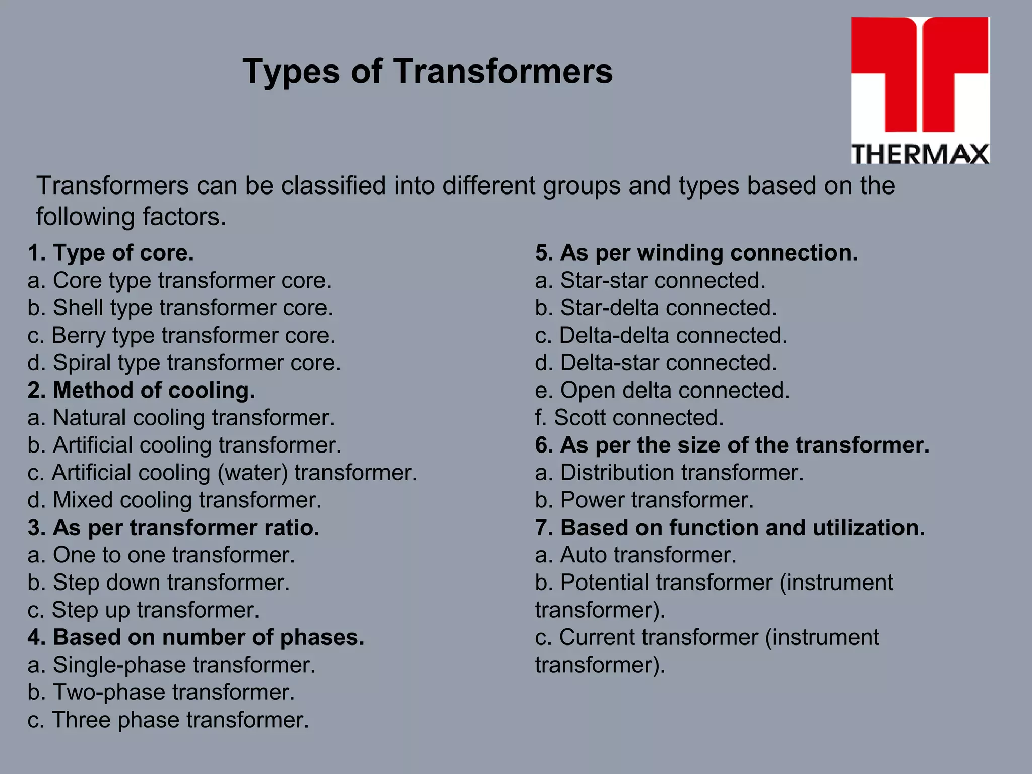
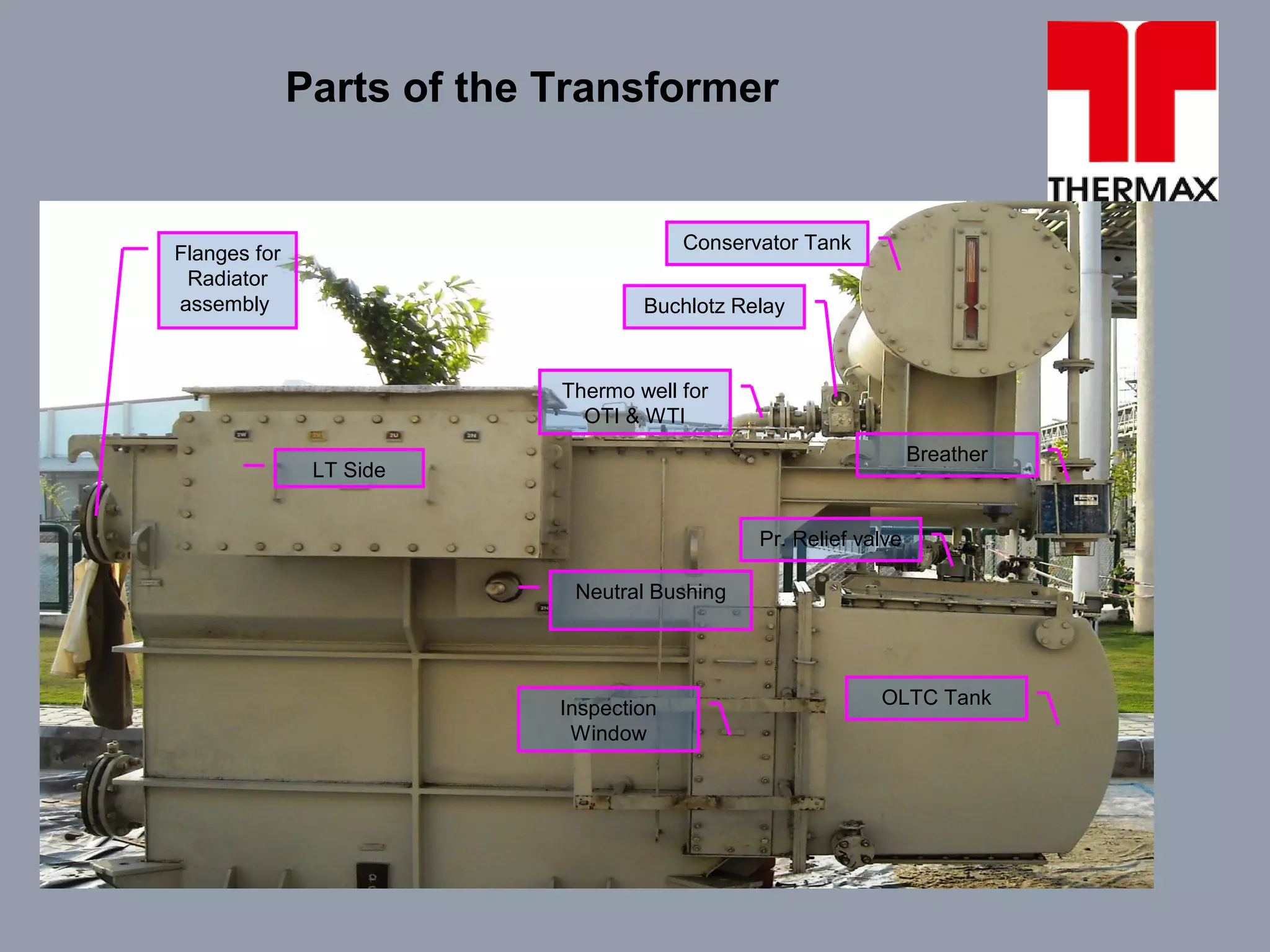
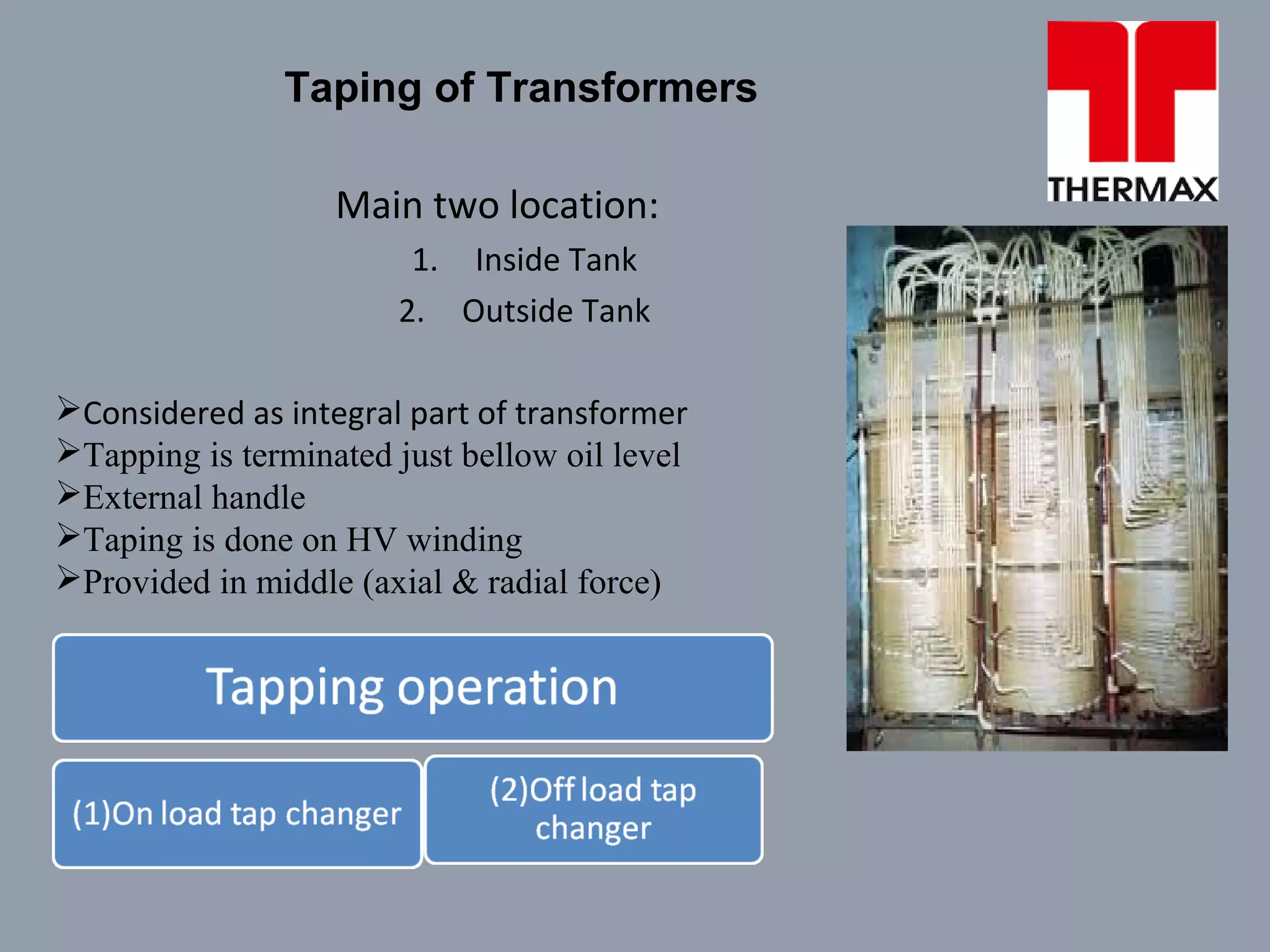
SlideShare a Scribd company logo
A
PRESENTATION
ON
OPERATION & MAINTENANCE OF DISTRIBUTION TRANSFORMERS
BY
PREPAIRED BY- KAPIL SINGH
(ENGINEER-THERMAX LTD. C&H SSBU O&M)
Definition:
Transformer is a static Electro – magnetic equipment which
transforms alternating current from one voltage level to another voltage
level with out change in frequency. Transformer transfers power from one
winding to another winding via a common magnetic core.
Working Principle:
A transformer works under the principle of mutual electro magnetic
induction (Faraday’s laws of Electro-magnetic induction). It says that, when
ever a changing flux links with a coil an emf is induced in it and this induced
emf is proportional to the rate of change of flux and the number of turns in
the coils linking the flux.
Definition & Working Principle of Transformer
Equation for transformation ratio is,
E2/E1 = N2/N1 = k
k = >1 in step up transformer, where secondary turns are more and thus
voltage is more to reduce the transmission current.
k = <1 in step down transformer, where secondary turns are less than
primary and low voltage for consumer use.
If we include the current in transformation ratio the equation is,
E2/E1 = N2/N1 = I1/I2 = k
Transformation Ratio
Purpose:
a. Electrical energy may be transmitted economically over long distance by
stepping up of voltages to reduce the line losses.
b. To distribute the low voltages at consumer side by stepping down the
voltages.
Advantage:
a. Transformer is a static machine and losses are very less. There by
efficiency is high and about 95 to 98%.
b. Practically maintenance is very less.
Purpose & Advantage
Transformers can be classified into different groups and types based on the
following factors.
Types of Transformers
1. Type of core.
a. Core type transformer core.
b. Shell type transformer core.
c. Berry type transformer core.
d. Spiral type transformer core.
2. Method of cooling.
a. Natural cooling transformer.
b. Artificial cooling transformer.
c. Artificial cooling (water) transformer.
d. Mixed cooling transformer.
3. As per transformer ratio.
a. One to one transformer.
b. Step down transformer.
c. Step up transformer.
4. Based on number of phases.
a. Single-phase transformer.
b. Two-phase transformer.
c. Three phase transformer.
5. As per winding connection.
a. Star-star connected.
b. Star-delta connected.
c. Delta-delta connected.
d. Delta-star connected.
e. Open delta connected.
f. Scott connected.
6. As per the size of the transformer.
a. Distribution transformer.
b. Power transformer.
7. Based on function and utilization.
a. Auto transformer.
b. Potential transformer (instrument
transformer).
c. Current transformer (instrument
transformer).
Parts of the Transformer
LT Side
Buchlotz Relay
Neutral Bushing
Breather
Conservator Tank
OLTC Tank
Pr. Relief valve
Inspection
Window
Flanges for
Radiator
assembly
Thermo well for
OTI & WTI
Parts of the Winding
HT winding
Tapping's
of windings
for OLTC
Core
HT
termination
LT
termination
Insulation of Transformers
Two main kinds of Insulations:
1.Major Insulation:
 Insulating cylinder between LV & core
 Also between HV & LV
 Insulating barriers between limbs, coils & core yoke
 Oil impregnated paper used as it has high dielectric strength
2.Minor Insulation:
 Insulation between
individual turns & between layers
 Conductor Insulation: paper & cotton
 Air insulated Transformer
insulation used is glass tap
Taping of Transformers
Main two location:
1. Inside Tank
2. Outside Tank
Considered as integral part of transformer
Tapping is terminated just bellow oil level
External handle
Taping is done on HV winding
Provided in middle (axial & radial force)
Daily operational check of the Transformer
1. H.T. Voltage and current reading.
2. L.T. Voltage and current reading.
3. WTI current and maximum reading
4. OTI current and maximum reading
5. Oil level in conservator tank
6. Oil level in OLTC tank
7. Tap position
8. Tap changer counter reading
9. Tap changer motor MPCB and limit switch status.
10. PRV status.
11. Buchholz relay status.
12. Condition of silica gel in breathers.
13. Cleanliness of transformer and accessories.
14. Visual leakage / seepage of oil.
15. Humming/any abnormal sound of transformer and accessories.
Quarterly check of the Transformer
1)Cleaning of Transformer
2)Note down of Maximum temp of HV LV Winding. & LV Winding.
3)Checking of OLTC mechanism Step by step
4)Tightening of HV & LV connection
5)Checking of gas collection in Buchholz relay, cleaning of glass cover
6)Operation of tap changer from local and remote.
7) Condition check/replacement of silica gel.
8) Alarm/Tripping signal checking of OTI,WTI,Buchholz and PRV signal at panel.
Yearly check of the Transformer
1. Cleaning of Transformer
2. Oil leakages checks for all joint
3. Note down of Maximum temp of HV LV Winding. & LV Winding.
4. Checking of OLTC mechanism Step by step
5. Tightening of HV & LV connection
6. Checking of gas collection in Buchholz relay, cleaning of glass cover
7. Operation of tap changer from local and remote.
8. Condition check/replacement of silica gel.
9. Alarm/Tripping signal checking of OTI,WTI,Buchholz and PRV signal at panel
10. Oil dehydration
11. BDV of main Oil and OLTC oil
12. PPM of oil.
13. Ratio test in every tap
14. Magnetizing current test.
15. Magnetic balance
16. Winding resistance
17. Insulation resistance.
18. Other inter lock if any.
Tests on the Transformer
Routine Test
1. Ratio and Polarity test
2. Load Losses
3. Impedance measurements
4. Insulation resistance
5. Resistance of windings
6. No load losses
7. No load current
8. Voltage test
a. Separate source
b. Induced voltage
9. Core insulation test
Type Test
1. Temperature rise test.
2. Impulse voltage test.
3. Noise level test
Special Test
1. Partial discharge.
2. Radio interference.
3. Vibration test.
4. Short circuit withstand test.
5. Tan delta test.
Characteristics of Transformer Oil
Characteristics Requirement Method of testing Remarks
Appearance The oil shall be clear
and transparent and
free from suspended
matter of sediments.
A representative sample of the oil
shall be examined in a 100-mm
thick layer at 27°C.
Density at 29.5°C
max.
0.89 gm / cm3 IS-1448(P:16):1977
Kinematic viscosity max.
at
a. 27°C
b. 40°C
27 cSt
under consideration
IS-1448(P:25):1976
Interfacial tension at 27°C
min.
0.04 N/m IS- 6104:1971
Flash point penskymarten
(closed)
140°C IS-1448(P:21):1970
Pour point max. -6°C IS-1448(P:10):1970
Characteristics of Transformer Oil
CharacteristicsCharacteristics RequirementRequirement Method of testingMethod of testing RemarksRemarks
Neutralization valueNeutralization value
a. Total acidity maxa. Total acidity max
b. Inorganicb. Inorganic
acidity/alkalinityacidity/alkalinity
0.03 mg KOH/g0.03 mg KOH/g
nilnil
IS-1448(P:2):1967IS-1448(P:2):1967
Alcoholic PotassiumAlcoholic Potassium
hydroxide solution ofhydroxide solution of
0.02 N should be in0.02 N should be in
place of 0.1 N Indicatedplace of 0.1 N Indicated
in test Method.in test Method.
Electric strengthElectric strength
(Breakdown voltage)(Breakdown voltage)
a. New unfiltered oil min.a. New unfiltered oil min.
b. After filtration min.b. After filtration min.
30 kV (rms)30 kV (rms)
If the above value is notIf the above value is not
attained the oilattained the oil
shall be filtered 60 kV.shall be filtered 60 kV.
IS-6792:1972IS-6792:1972 See noteSee note
mentioned belowmentioned below
Dielectric dissipationDielectric dissipation
factor (tanfactor (tan δδ) at 90) at 90°°CC
max.max.
0.0020.002 IS-6262:1971IS-6262:1971
Specific resistanceSpecific resistance
(resistivity)(resistivity)
a. At 90a. At 90°°C min.C min.
b. At 27b. At 27°°C min.C min.
35 * 1035 * 101212 ΩΩ-cm-cm
1500* 101500* 101212 ΩΩ-cm-cm
IS-6103:1971IS-6103:1971
Note: As a consequence of the tendency for water absorption to occur due to breathing on storage even when drums are sealed the oil shall be
filtered to remove moisture and particulate contaminates present in the original sample before the test as follows.
a. A sufficient quantity of oil is heated to 90 ± 2°C, then filtered hot under vacuum corresponding to an absolute pressure of about 2.5 kPa
through a sintered glass filter of porosity grade 4’.
b. A portion of filtered is cooled in a desiccator and used immediately to measure electric strength, if required, and specific resistance at 27°C.
The remaining hot filtrate is immediately used for measuring dielectric dissipation factor at 90°C and specific resistance at 90°C.
Characteristics of Transformer Oil
CharacteristicsCharacteristics RequirementRequirement Method of testingMethod of testing RemarksRemarks
Ageing characteristics
after
accelerated ageing
(open beaker method
with copper catalyst)
a. Specific resistance
at
27°C min. & at 90°C
min..
b. Tan δ at 90°C max.
c. Total acidity max
d. Total sludge max.
2.5 * 1012Ω-cm
0.2 * 1012Ω-cm
0.2
0.05 mg KOH/g
0.05% by weight.
IS-12177:1987
IS-6103:1971
IS-6262:1971
IS-1448(P:2):1967
IS-12177
Presence oxidation
inhibitor
The oil shall contain
antioxidant additives
IS-13631:1992 See note below
Note: For both phenol and amine types of indicators, qualitative methods shall be adopted. In case of ambiguity (marginal cases) in finding the
intensity of colour, a quantitativemethod shall be adopted. Value of 0.5 (max.) shall be treated as absence of DBPCPhenolic type inhibitor
(quantitative method for amine is under consideration).
Water content max. 50 ppm IS-13567:1992
Transformer oil Brands available in market
confirming to different
Standards/specifications as per products
Tests to be conducted on the Transformer
Test Purpose Item Required condition of transformer
IR value and PI
value.
Detects serious flaws, moisture
absorption and cleanliness of
winding. Winding. Winding has to be isolated.
Tan delta or dielectric
loss or power factor
or HV test.
Indicates insulation deterioration,
contamination and physical damage.
Winding, oil and
bushings.
Winding has to be isolated,
oil sample should be collected.
Excitation current at
high voltage.
Indicates defects in the magnetic core
structure, shifting or windings, failures
in turn to turn insulation. Winding Winding has to be isolated.
Turns ratio
Indicates short circuited turns and
internal connections Winding Winding has to be isolated.
Winding resistance Detects poor connections and
conductor shorts Winding Winding has to be isolated.
Core IR and
inadvertent grounds
Indicates deterioration of core
insulation system Core Winding has to be isolated.
Water contents Indicates moisture level in oil Oil Oil sample has to be collected
Total acidity,
neutralization number
Measures organic and inorganic
acids Oil Oil sample has to be collected
Dissolved
gas analysis
Indicates specific gases
generated Oil Oil sample has to be collected
Furanite compounds Indicates cellulose degradation Winding Oil sample has to be collected
First Stage: When we start the filtering process initially the temperature will be low, as the
insulation value is high. But as temperature increases the IR value starts to decrease because
the moisture entrapped in the coils are released due to rise in temperature and this causes the
IR value to go down.
Second Stage: Then comes the point where all the moisture is released and then will be no
decrease in IR value or rise in the temperature.
Third Stage: At this point the heaters are switched off. Now the moisture is removed by the oil
filters and the IR value goes up and as the heaters are off the temperature decreases.
Drying out of Transformer
150
700
1 2 3 4 5 6 7 8 9 10 11 12 13 14 15 16 17
Time
IRVaule
25
Temperature
Stage 1
Stage 2
Stage 3
Temperature
At this point the heaters
are switched off
IR
Humming in the transformer is a sound, which is produced due to the
vibration of the cores in the transformer.
The vibrations are produced due to the change in polarity of an
alternating current or voltage and by the loose of lamination of the core.
Both can be minimized by tightening the core of the transformer.
Humming Sound of the Transformer
Ratio test - Apply 3ph, 415V to high voltage winding of the transformer and
measure the induced voltage on the low voltage terminals at all taps. Ensure
variation in secondary volts as the taps are changed and compare the results
with manufacturers test report or ratio mentioned on transformer nameplate. If
delta tertiary stabilizing winding is provided (usually provided for Y-Y
transformers), open the delta shorting link and measure the voltage across the
two terminals during ratio test - it should be negligible.
No load / magnetising current test - Remove the shorting between primary &
secondary and measure the currents in all the phases while maintaining the
supply at primary. This test is done at nominal tap, and at the minimum and
maximum taps.
Expected currents - Ir / Iy / Ib-- 1: 0.8: 1 for star transformer
- Ir / Iy / Ib-- 1: 1: 1.3 for delta transformer
Ratio Test and No Load Test
Short circuit test
With the transformer at nominal tap, apply 3ph ,415V to the primary and
adequate shorting on the secondary side( depending on % impedance );
ensure bushing CT secondary’s and WTI CT secondary’s are through.
a) Measure currents in primary and secondary
b) Check the currents in CT secondary of bushing CT, WTI CT, and LDC CT.
Repeat point (a) at maximum & minimum taps.
Core balance test
Apply 415V between phase-phase (for delta transformer) and phase-neutral (for
star transformer) on secondary side. Ensure that adequate safety precautions
are taken on the primary side, as high voltage will be induced.
Measure the current and voltages for the following phases--
For delta trafo - Vry, Vyb, Vbr
For star trafo - Vry, Vyb, Vbr, Vrn, Vyn, Vbn.
Short Circuit and Core Balance Test
Insulation test
Insulation tester of 2.5 or 5 KV may be used. Polarisation index is recorded by IR
value at 10/1 min ratio.
Insulation Test
PI Value
Insulation
Condition
Recommendation
1.0 to 1.5 Bad
Drying is
Mandatory
1.5 to 2 Doubtful
Drying is
recommended.
2.0 to 3.0 Good
No drying is
required.
3.0 to 4.0 Excellent
No drying is
required.
Transformer oil testing at site:
Prior to charging of transformer confirm the healthiness of the oil by testing the
dielectric strength of oil. The oil is to be tested at 2.5 mm gap. 3 readings have
to be taken and a average of these readings is the ‘breakdown voltage of the
oil’. BDV should be >60 KV.
Transformer Oil Testing
Transformer oil testing at Lab:
 Electric strength
 Water contents
 Dissolved gas analysis
 Dielectric dissipation factor (Dielectric dissipation factor (Tan δ)
 Total acidity max
 Total sludge max
In transformer there are mainly three types of losses
1-iron loss or core loss
2-Copper loss or I
2
R loss.
3-Stray and Dielectric loss.
These losses due to,
1. Resistance of the winding (copper losses).
2. Eddy current and Hysteresis in the iron parts and core (core and iron losses).
3. Losses due to leakage reactance (leakage flux).
At No load the copper losses and leakage flux losses are negligible due to the very
less primary current.
At loaded condition copper losses and leakage flux losses will exist in considerable
manner.
Copper losses are variable and can be calculated by Ip2
*Rp and Is2
*Rs.
(Where I-current , R-resistance p-primary winding s-secondary winding)
Losses in the Transformer
1. Check oil leakage from bushings, valves, air release plugs, etc.
2. Direction of mounting of Buchholz relay, as per arrow on the relay; the arrow
should point towards the conservator
3. Oil level in condenser bushings
4. Oil level of Main Tank and OLTC Tank should be up to the filling mark on MOG
(Minimum Oil Level Gauge)
5. Transformer is earthed at two points
6. Stoppers provided for locking of wheels
7. Test taps on HV condenser bushings are fixed Valves on each radiator, both top
and bottom, should be open.
8. Valves on either side of Buchholz relay should be open
10. Tightness of conductors / cables on Trafo. HV side, LV side and Neutral.
11. Check resistance and IR value of NGR, if provided
12. Check that oil is filled in OTI and WTI pockets.
13. Check that colour of silica gel in breathers of main conservator and OLTC
conservator is blue.
14. Oil in breather cups to be filled up to level indicated
Commissioning Procedure for a Transformer
.
OLTC separate chamber type
OLTC in-built in the main tank
a) For in-built OLTC (diverter switch) ensure that the tap number on the Drive mechanism
(DM) is same as the one in the display on the main tank. Then connect the main
operating rod between the OLTC DM and diverter switch.
Conduct mechanical operations on the OLTC taking it through all the taps. Ensure that
the final end position (upper and lower limit) switches operate.
b) During the raise / lower operation note the direction of operating mechanism. Switch’ off’
the 3 PH AC supply and check operation of raise/lower contactor as per commands from
DM.
c) With OLTC at some intermediate tap, switch on the 3 phase supply and give either raise /
lower command to the OLTC. Check whether the mechanism is moving in the right
direction for the command given. If the direction is reverse, switch ‘off’ the AC & DC
supply, verify that the phase sequence of the supply is correct; if not correct, reverse the
phase sequence at the motor terminal box.
d) Observe the operation of OLTC and check blocking of operation at the end positions
e) Verify that insertion of manual operating handle cuts off electrical operation.
f) Test the Automatic Voltage Regulating Relay (AVRR), if provided. Perform automatic
operation from the AVRR.
Commissioning Procedure for an
OLTC of Transformer
1. Cleaning of the transformer, especially the bushings. Ensure that all protections are
operative. Buchholz relay maybe tested by using the test screw, or by pumping in air with
a bicycle pump , or by draining oil from the relay after closing both side valves.
2. Air release from the transformer is to be done from air release plugs on the main tank,
radiators, HV &LV bushings, Buchholz relay and OLTC prior to charging of transformer.
Do not release air from the Condenser bushings as they are hermetically sealed.
3. Check operation of OTI/WTI, ensure oil in the temperature probe pots.
4. Check that all interconnecting valves are in open position.
5. Check IR values between each winding an earth, and between windings. Neutral
earthing is to be disconnected for this purpose.
6. Check that HV and LV neutral earthing has been re–connected after megger test.
7. Earthing and delta shorting of tertiary stabilizing winding (if provided), to be checked.
8. Proper setting of OTI & WTI to be done.
9. Perform trip test from all the transformer protections, including Buchholz relay, PRD, Oil
surge relay, OTI and WTI.
10. All protection relays to be properly set.
11. Reset the Maximum Reading Pointer (MRP) of OTI & WTI.
12. Ammeter selector switches should be selected to read some phase current.
13. All MCBs, fuses and switches in Marshalling boxes, CRPs, isolator cubicles and breaker
cubicles should be in circuit.
14. If the transformer is provided with an OLTC, energise it at Tap #1; if the transformer is
provided with an off-circuit tap changer, energise it at the nominal tap.
Prior to Energizing the Transformer
After energising the transformer :
1. If OLTC is provided, run the tap changer from Tap #1 up to nominal tap.
2. Check the phase sequence and magnitude of the transformer secondary
voltage at the incoming line PTs.
3. If the transformer is an extension to an existing system, do the phasing out
w.r.t. the existing PTs.
4. Check for any abnormal sound or vibration in the transformer.
5. Keep the transformer energised on no-load for 24 hours; take readings of
OTI, WTI and current.
After Energizing the Transformer
CONDITIONS LEADING TO FAULTS
Insulation breakdown
Aging of insulation
Overheating due to over excitation
Oil contamination and leakage
Reduced cooling
External circuit fault
NATURE OF TRANSFORMER FAULTS
Although an electrical power transformer is a static device, but internal stresses
arising from abnormal system conditions, must be taken into consideration.
A transformer generally suffers from following types of transformer fault-Over
current due to overloads and external short circuits,
Terminal faults,
Winding faults,
Incipient faults.
All the above mentioned transformer faults cause mechanical and thermal stresses
inside the transformer winding and its connecting terminals. Thermal stresses lead
to overheating which ultimately affect the insulation system of transformer.
Deterioration of insulation leads to winding faults. Some time failure of transformer
cooling system leads to overheating of transformer. So the transformer protection
schemes are very much required.
The short circuit current of an electrical transformer is normally limited by its
reactance and for low reactance, the value of short circuit current may be
excessively high.
TRANSFORMER PROTECTION
It is common practice to provide buchholz relay protection to all 0.5 MVA and above
transformers. While for all small size distribution transformers, only high voltage
fuses are used as main protective device. For all larger rated and important
distribution transformers, over current protection along with restricted earth fault
protection is applied. Differential protection should be provided in the transformers
rated above 5 MVA. Depending upon the normal service condition, nature of
transformer faults, degree of sustained over load, scheme of tap changing, and
many other factors, the suitable transformer protection schemes are chosen
Some Typical protection equipments are enlisted below
1.Buchholz relay
2.PRV
3.OTI
4.WTI
5.MOG
6.O/V current and E/F relay
7.Differential protection relay
ch
THANK YOU
C&H SSBU O&M REGION-DELHI

More Related Content

What's hot

Relay coordination
Relay coordinationRelay coordination
Relay coordination
D Målîk
 
Tan delta test for power transformers
Tan delta test for power transformersTan delta test for power transformers
Tan delta test for power transformers
jibinjoy1988
 
Types of relay
Types of relayTypes of relay
Types of relay
Abdur rehman
 
Substation protection devices
Substation protection devicesSubstation protection devices
Substation protection devices
Rahul Aman
 
Distribution Transformer testing, West Bengal, India
Distribution Transformer testing,  West Bengal, IndiaDistribution Transformer testing,  West Bengal, India
Distribution Transformer testing, West Bengal, India
RajuMondal18
 
Motor starter
Motor starterMotor starter
Motor starter
BHAGWAN PRASAD
 
HT and LT SWITCHGEAR
HT and LT SWITCHGEARHT and LT SWITCHGEAR
HT and LT SWITCHGEAR
Ravindra Kumar
 
Power Transformer Differential protection
Power Transformer Differential protectionPower Transformer Differential protection
Power Transformer Differential protection
Rishi Tandon
 
Power Transformer Parts And Functions
Power Transformer Parts And FunctionsPower Transformer Parts And Functions
Power Transformer Parts And Functions
Nitendra Kumar Singh
 
Relays and its types - complete guide
Relays and its types - complete guideRelays and its types - complete guide
Relays and its types - complete guide
Slides Hub
 
Ppt on protection of power transformers
Ppt on protection of power transformersPpt on protection of power transformers
Ppt on protection of power transformers
siddharam kantoli
 
Soft starters
Soft startersSoft starters
Soft starters
michaeljmack
 
Protective relay
Protective relay Protective relay
Protective relay
Uday Wankar
 
Power Transformer Protection
Power Transformer ProtectionPower Transformer Protection
Power Transformer Protection
Ang Sovann
 
Unit 03 Protective relays
Unit  03 Protective relaysUnit  03 Protective relays
Unit 03 Protective relays
PremanandDesai
 
Testing of circuit breakers
Testing of circuit breakersTesting of circuit breakers
Testing of circuit breakers
Kabilesh K
 
Switchgear presentation
Switchgear presentationSwitchgear presentation
Switchgear presentation
Nikhil Kachare
 
Protection Of Generator
Protection Of GeneratorProtection Of Generator
Protection Of Generator
Rahuldey1991
 

What's hot (20)

Relay coordination
Relay coordinationRelay coordination
Relay coordination
 
Tan delta test for power transformers
Tan delta test for power transformersTan delta test for power transformers
Tan delta test for power transformers
 
Types of relay
Types of relayTypes of relay
Types of relay
 
BUSBAR PROTECTION
BUSBAR PROTECTIONBUSBAR PROTECTION
BUSBAR PROTECTION
 
Substation protection devices
Substation protection devicesSubstation protection devices
Substation protection devices
 
Reactive power compensation
Reactive power compensationReactive power compensation
Reactive power compensation
 
Distribution Transformer testing, West Bengal, India
Distribution Transformer testing,  West Bengal, IndiaDistribution Transformer testing,  West Bengal, India
Distribution Transformer testing, West Bengal, India
 
Motor starter
Motor starterMotor starter
Motor starter
 
HT and LT SWITCHGEAR
HT and LT SWITCHGEARHT and LT SWITCHGEAR
HT and LT SWITCHGEAR
 
Power Transformer Differential protection
Power Transformer Differential protectionPower Transformer Differential protection
Power Transformer Differential protection
 
Power Transformer Parts And Functions
Power Transformer Parts And FunctionsPower Transformer Parts And Functions
Power Transformer Parts And Functions
 
Relays and its types - complete guide
Relays and its types - complete guideRelays and its types - complete guide
Relays and its types - complete guide
 
Ppt on protection of power transformers
Ppt on protection of power transformersPpt on protection of power transformers
Ppt on protection of power transformers
 
Soft starters
Soft startersSoft starters
Soft starters
 
Protective relay
Protective relay Protective relay
Protective relay
 
Power Transformer Protection
Power Transformer ProtectionPower Transformer Protection
Power Transformer Protection
 
Unit 03 Protective relays
Unit  03 Protective relaysUnit  03 Protective relays
Unit 03 Protective relays
 
Testing of circuit breakers
Testing of circuit breakersTesting of circuit breakers
Testing of circuit breakers
 
Switchgear presentation
Switchgear presentationSwitchgear presentation
Switchgear presentation
 
Protection Of Generator
Protection Of GeneratorProtection Of Generator
Protection Of Generator
 

Similar to Operation and maintenance of transformer

transformers.ppt
transformers.ppttransformers.ppt
transformers.ppt
mohamedtaha40900
 
PROTECTIVE DEVICES & MAINTENANCE.ppt
PROTECTIVE DEVICES & MAINTENANCE.pptPROTECTIVE DEVICES & MAINTENANCE.ppt
PROTECTIVE DEVICES & MAINTENANCE.ppt
Qwer401863
 
Testing and Condition Monitoring of Substation Equipments
Testing and Condition Monitoring of Substation EquipmentsTesting and Condition Monitoring of Substation Equipments
Testing and Condition Monitoring of Substation Equipments
Sumeet Ratnawat
 
Transformer
TransformerTransformer
Transformer
Sandeep Kumar
 
Power transformer testing and commissioning guidelines r
Power transformer testing and commissioning guidelines rPower transformer testing and commissioning guidelines r
Power transformer testing and commissioning guidelines r
Ashish Patel
 
PRESENTATION ON MANUFACTURING OF TRANSFORMER By Dhruv Jimit
PRESENTATION ON MANUFACTURING OF TRANSFORMER By Dhruv JimitPRESENTATION ON MANUFACTURING OF TRANSFORMER By Dhruv Jimit
PRESENTATION ON MANUFACTURING OF TRANSFORMER By Dhruv Jimit
Jimit Dhruv
 
tcee-161003100321.pptx
tcee-161003100321.pptxtcee-161003100321.pptx
tcee-161003100321.pptx
Satish Pydimarla
 
Inspection and Testing of various electrical equipment
Inspection and Testing of various electrical equipmentInspection and Testing of various electrical equipment
Inspection and Testing of various electrical equipment
AkankshaSharma570781
 
3 condition monitoring of oil
3 condition monitoring of oil3 condition monitoring of oil
3 condition monitoring of oil
Udhayakumar Venkataraman
 
Transformer Repair Workshop Report [EEE]
Transformer Repair Workshop Report [EEE] Transformer Repair Workshop Report [EEE]
Transformer Repair Workshop Report [EEE]
Nik Sharma
 
Tranformer general , operation and maintenace by walid
Tranformer general , operation and maintenace by walidTranformer general , operation and maintenace by walid
Tranformer general , operation and maintenace by walid
Walidkarim884
 
CIRCUIT BREAKER USED IN THERMAL POWER PLANTS
CIRCUIT BREAKER USED IN THERMAL POWER PLANTSCIRCUIT BREAKER USED IN THERMAL POWER PLANTS
CIRCUIT BREAKER USED IN THERMAL POWER PLANTS
DigantaSinha1
 
Maintenance schedule of Substation.
Maintenance schedule of Substation.Maintenance schedule of Substation.
Maintenance schedule of Substation.
Sheikh Nazmul Islam
 
Presentation_Power_Transformers-1
Presentation_Power_Transformers-1Presentation_Power_Transformers-1
Presentation_Power_Transformers-1Nageswar Rao
 
Power-Transformer-Testing-Brochure-ENU.pdf
Power-Transformer-Testing-Brochure-ENU.pdfPower-Transformer-Testing-Brochure-ENU.pdf
Power-Transformer-Testing-Brochure-ENU.pdf
NguyenXuanTung12
 
Testing of transformer
Testing of transformerTesting of transformer
Testing of transformer
vikasgupta1965
 
Liquid Insulation Dissipation factor and Dielectric Factor Measurement Unit
Liquid Insulation Dissipation factor and Dielectric Factor Measurement UnitLiquid Insulation Dissipation factor and Dielectric Factor Measurement Unit
Liquid Insulation Dissipation factor and Dielectric Factor Measurement Unit
NadiiaHubar
 
TESTING,MAINTENANCE&PROTECTION.ppt
TESTING,MAINTENANCE&PROTECTION.pptTESTING,MAINTENANCE&PROTECTION.ppt
TESTING,MAINTENANCE&PROTECTION.ppt
ChristinaBoyd12
 

Similar to Operation and maintenance of transformer (20)

transformers.ppt
transformers.ppttransformers.ppt
transformers.ppt
 
PROTECTIVE DEVICES & MAINTENANCE.ppt
PROTECTIVE DEVICES & MAINTENANCE.pptPROTECTIVE DEVICES & MAINTENANCE.ppt
PROTECTIVE DEVICES & MAINTENANCE.ppt
 
Testing and Condition Monitoring of Substation Equipments
Testing and Condition Monitoring of Substation EquipmentsTesting and Condition Monitoring of Substation Equipments
Testing and Condition Monitoring of Substation Equipments
 
Transformer
TransformerTransformer
Transformer
 
Power transformer testing and commissioning guidelines r
Power transformer testing and commissioning guidelines rPower transformer testing and commissioning guidelines r
Power transformer testing and commissioning guidelines r
 
PRESENTATION ON MANUFACTURING OF TRANSFORMER By Dhruv Jimit
PRESENTATION ON MANUFACTURING OF TRANSFORMER By Dhruv JimitPRESENTATION ON MANUFACTURING OF TRANSFORMER By Dhruv Jimit
PRESENTATION ON MANUFACTURING OF TRANSFORMER By Dhruv Jimit
 
tcee-161003100321.pptx
tcee-161003100321.pptxtcee-161003100321.pptx
tcee-161003100321.pptx
 
Inspection and Testing of various electrical equipment
Inspection and Testing of various electrical equipmentInspection and Testing of various electrical equipment
Inspection and Testing of various electrical equipment
 
3 condition monitoring of oil
3 condition monitoring of oil3 condition monitoring of oil
3 condition monitoring of oil
 
Transformer Repair Workshop Report [EEE]
Transformer Repair Workshop Report [EEE] Transformer Repair Workshop Report [EEE]
Transformer Repair Workshop Report [EEE]
 
Tranformer general , operation and maintenace by walid
Tranformer general , operation and maintenace by walidTranformer general , operation and maintenace by walid
Tranformer general , operation and maintenace by walid
 
CIRCUIT BREAKER USED IN THERMAL POWER PLANTS
CIRCUIT BREAKER USED IN THERMAL POWER PLANTSCIRCUIT BREAKER USED IN THERMAL POWER PLANTS
CIRCUIT BREAKER USED IN THERMAL POWER PLANTS
 
Maintenance schedule of Substation.
Maintenance schedule of Substation.Maintenance schedule of Substation.
Maintenance schedule of Substation.
 
Presentation_Power_Transformers-1
Presentation_Power_Transformers-1Presentation_Power_Transformers-1
Presentation_Power_Transformers-1
 
Executive summary
Executive summaryExecutive summary
Executive summary
 
Wapda Engineering Acadmy Report
Wapda Engineering Acadmy ReportWapda Engineering Acadmy Report
Wapda Engineering Acadmy Report
 
Power-Transformer-Testing-Brochure-ENU.pdf
Power-Transformer-Testing-Brochure-ENU.pdfPower-Transformer-Testing-Brochure-ENU.pdf
Power-Transformer-Testing-Brochure-ENU.pdf
 
Testing of transformer
Testing of transformerTesting of transformer
Testing of transformer
 
Liquid Insulation Dissipation factor and Dielectric Factor Measurement Unit
Liquid Insulation Dissipation factor and Dielectric Factor Measurement UnitLiquid Insulation Dissipation factor and Dielectric Factor Measurement Unit
Liquid Insulation Dissipation factor and Dielectric Factor Measurement Unit
 
TESTING,MAINTENANCE&PROTECTION.ppt
TESTING,MAINTENANCE&PROTECTION.pptTESTING,MAINTENANCE&PROTECTION.ppt
TESTING,MAINTENANCE&PROTECTION.ppt
 

Recently uploaded

RAT: Retrieval Augmented Thoughts Elicit Context-Aware Reasoning in Long-Hori...
RAT: Retrieval Augmented Thoughts Elicit Context-Aware Reasoning in Long-Hori...RAT: Retrieval Augmented Thoughts Elicit Context-Aware Reasoning in Long-Hori...
RAT: Retrieval Augmented Thoughts Elicit Context-Aware Reasoning in Long-Hori...
thanhdowork
 
AP LAB PPT.pdf ap lab ppt no title specific
AP LAB PPT.pdf ap lab ppt no title specificAP LAB PPT.pdf ap lab ppt no title specific
AP LAB PPT.pdf ap lab ppt no title specific
BrazilAccount1
 
NO1 Uk best vashikaran specialist in delhi vashikaran baba near me online vas...
NO1 Uk best vashikaran specialist in delhi vashikaran baba near me online vas...NO1 Uk best vashikaran specialist in delhi vashikaran baba near me online vas...
NO1 Uk best vashikaran specialist in delhi vashikaran baba near me online vas...
Amil Baba Dawood bangali
 
The role of big data in decision making.
The role of big data in decision making.The role of big data in decision making.
The role of big data in decision making.
ankuprajapati0525
 
J.Yang, ICLR 2024, MLILAB, KAIST AI.pdf
J.Yang,  ICLR 2024, MLILAB, KAIST AI.pdfJ.Yang,  ICLR 2024, MLILAB, KAIST AI.pdf
J.Yang, ICLR 2024, MLILAB, KAIST AI.pdf
MLILAB
 
The Benefits and Techniques of Trenchless Pipe Repair.pdf
The Benefits and Techniques of Trenchless Pipe Repair.pdfThe Benefits and Techniques of Trenchless Pipe Repair.pdf
The Benefits and Techniques of Trenchless Pipe Repair.pdf
Pipe Restoration Solutions
 
Water Industry Process Automation and Control Monthly - May 2024.pdf
Water Industry Process Automation and Control Monthly - May 2024.pdfWater Industry Process Automation and Control Monthly - May 2024.pdf
Water Industry Process Automation and Control Monthly - May 2024.pdf
Water Industry Process Automation & Control
 
weather web application report.pdf
weather web application report.pdfweather web application report.pdf
weather web application report.pdf
Pratik Pawar
 
Cosmetic shop management system project report.pdf
Cosmetic shop management system project report.pdfCosmetic shop management system project report.pdf
Cosmetic shop management system project report.pdf
Kamal Acharya
 
Runway Orientation Based on the Wind Rose Diagram.pptx
Runway Orientation Based on the Wind Rose Diagram.pptxRunway Orientation Based on the Wind Rose Diagram.pptx
Runway Orientation Based on the Wind Rose Diagram.pptx
SupreethSP4
 
Final project report on grocery store management system..pdf
Final project report on grocery store management system..pdfFinal project report on grocery store management system..pdf
Final project report on grocery store management system..pdf
Kamal Acharya
 
ethical hacking-mobile hacking methods.ppt
ethical hacking-mobile hacking methods.pptethical hacking-mobile hacking methods.ppt
ethical hacking-mobile hacking methods.ppt
Jayaprasanna4
 
一比一原版(IIT毕业证)伊利诺伊理工大学毕业证成绩单专业办理
一比一原版(IIT毕业证)伊利诺伊理工大学毕业证成绩单专业办理一比一原版(IIT毕业证)伊利诺伊理工大学毕业证成绩单专业办理
一比一原版(IIT毕业证)伊利诺伊理工大学毕业证成绩单专业办理
zwunae
 
Industrial Training at Shahjalal Fertilizer Company Limited (SFCL)
Industrial Training at Shahjalal Fertilizer Company Limited (SFCL)Industrial Training at Shahjalal Fertilizer Company Limited (SFCL)
Industrial Training at Shahjalal Fertilizer Company Limited (SFCL)
MdTanvirMahtab2
 
Standard Reomte Control Interface - Neometrix
Standard Reomte Control Interface - NeometrixStandard Reomte Control Interface - Neometrix
Standard Reomte Control Interface - Neometrix
Neometrix_Engineering_Pvt_Ltd
 
一比一原版(UofT毕业证)多伦多大学毕业证成绩单如何办理
一比一原版(UofT毕业证)多伦多大学毕业证成绩单如何办理一比一原版(UofT毕业证)多伦多大学毕业证成绩单如何办理
一比一原版(UofT毕业证)多伦多大学毕业证成绩单如何办理
ydteq
 
Design and Analysis of Algorithms-DP,Backtracking,Graphs,B&B
Design and Analysis of Algorithms-DP,Backtracking,Graphs,B&BDesign and Analysis of Algorithms-DP,Backtracking,Graphs,B&B
Design and Analysis of Algorithms-DP,Backtracking,Graphs,B&B
Sreedhar Chowdam
 
CME397 Surface Engineering- Professional Elective
CME397 Surface Engineering- Professional ElectiveCME397 Surface Engineering- Professional Elective
CME397 Surface Engineering- Professional Elective
karthi keyan
 
ethical hacking in wireless-hacking1.ppt
ethical hacking in wireless-hacking1.pptethical hacking in wireless-hacking1.ppt
ethical hacking in wireless-hacking1.ppt
Jayaprasanna4
 
一比一原版(SFU毕业证)西蒙菲莎大学毕业证成绩单如何办理
一比一原版(SFU毕业证)西蒙菲莎大学毕业证成绩单如何办理一比一原版(SFU毕业证)西蒙菲莎大学毕业证成绩单如何办理
一比一原版(SFU毕业证)西蒙菲莎大学毕业证成绩单如何办理
bakpo1
 

Recently uploaded (20)

RAT: Retrieval Augmented Thoughts Elicit Context-Aware Reasoning in Long-Hori...
RAT: Retrieval Augmented Thoughts Elicit Context-Aware Reasoning in Long-Hori...RAT: Retrieval Augmented Thoughts Elicit Context-Aware Reasoning in Long-Hori...
RAT: Retrieval Augmented Thoughts Elicit Context-Aware Reasoning in Long-Hori...
 
AP LAB PPT.pdf ap lab ppt no title specific
AP LAB PPT.pdf ap lab ppt no title specificAP LAB PPT.pdf ap lab ppt no title specific
AP LAB PPT.pdf ap lab ppt no title specific
 
NO1 Uk best vashikaran specialist in delhi vashikaran baba near me online vas...
NO1 Uk best vashikaran specialist in delhi vashikaran baba near me online vas...NO1 Uk best vashikaran specialist in delhi vashikaran baba near me online vas...
NO1 Uk best vashikaran specialist in delhi vashikaran baba near me online vas...
 
The role of big data in decision making.
The role of big data in decision making.The role of big data in decision making.
The role of big data in decision making.
 
J.Yang, ICLR 2024, MLILAB, KAIST AI.pdf
J.Yang,  ICLR 2024, MLILAB, KAIST AI.pdfJ.Yang,  ICLR 2024, MLILAB, KAIST AI.pdf
J.Yang, ICLR 2024, MLILAB, KAIST AI.pdf
 
The Benefits and Techniques of Trenchless Pipe Repair.pdf
The Benefits and Techniques of Trenchless Pipe Repair.pdfThe Benefits and Techniques of Trenchless Pipe Repair.pdf
The Benefits and Techniques of Trenchless Pipe Repair.pdf
 
Water Industry Process Automation and Control Monthly - May 2024.pdf
Water Industry Process Automation and Control Monthly - May 2024.pdfWater Industry Process Automation and Control Monthly - May 2024.pdf
Water Industry Process Automation and Control Monthly - May 2024.pdf
 
weather web application report.pdf
weather web application report.pdfweather web application report.pdf
weather web application report.pdf
 
Cosmetic shop management system project report.pdf
Cosmetic shop management system project report.pdfCosmetic shop management system project report.pdf
Cosmetic shop management system project report.pdf
 
Runway Orientation Based on the Wind Rose Diagram.pptx
Runway Orientation Based on the Wind Rose Diagram.pptxRunway Orientation Based on the Wind Rose Diagram.pptx
Runway Orientation Based on the Wind Rose Diagram.pptx
 
Final project report on grocery store management system..pdf
Final project report on grocery store management system..pdfFinal project report on grocery store management system..pdf
Final project report on grocery store management system..pdf
 
ethical hacking-mobile hacking methods.ppt
ethical hacking-mobile hacking methods.pptethical hacking-mobile hacking methods.ppt
ethical hacking-mobile hacking methods.ppt
 
一比一原版(IIT毕业证)伊利诺伊理工大学毕业证成绩单专业办理
一比一原版(IIT毕业证)伊利诺伊理工大学毕业证成绩单专业办理一比一原版(IIT毕业证)伊利诺伊理工大学毕业证成绩单专业办理
一比一原版(IIT毕业证)伊利诺伊理工大学毕业证成绩单专业办理
 
Industrial Training at Shahjalal Fertilizer Company Limited (SFCL)
Industrial Training at Shahjalal Fertilizer Company Limited (SFCL)Industrial Training at Shahjalal Fertilizer Company Limited (SFCL)
Industrial Training at Shahjalal Fertilizer Company Limited (SFCL)
 
Standard Reomte Control Interface - Neometrix
Standard Reomte Control Interface - NeometrixStandard Reomte Control Interface - Neometrix
Standard Reomte Control Interface - Neometrix
 
一比一原版(UofT毕业证)多伦多大学毕业证成绩单如何办理
一比一原版(UofT毕业证)多伦多大学毕业证成绩单如何办理一比一原版(UofT毕业证)多伦多大学毕业证成绩单如何办理
一比一原版(UofT毕业证)多伦多大学毕业证成绩单如何办理
 
Design and Analysis of Algorithms-DP,Backtracking,Graphs,B&B
Design and Analysis of Algorithms-DP,Backtracking,Graphs,B&BDesign and Analysis of Algorithms-DP,Backtracking,Graphs,B&B
Design and Analysis of Algorithms-DP,Backtracking,Graphs,B&B
 
CME397 Surface Engineering- Professional Elective
CME397 Surface Engineering- Professional ElectiveCME397 Surface Engineering- Professional Elective
CME397 Surface Engineering- Professional Elective
 
ethical hacking in wireless-hacking1.ppt
ethical hacking in wireless-hacking1.pptethical hacking in wireless-hacking1.ppt
ethical hacking in wireless-hacking1.ppt
 
一比一原版(SFU毕业证)西蒙菲莎大学毕业证成绩单如何办理
一比一原版(SFU毕业证)西蒙菲莎大学毕业证成绩单如何办理一比一原版(SFU毕业证)西蒙菲莎大学毕业证成绩单如何办理
一比一原版(SFU毕业证)西蒙菲莎大学毕业证成绩单如何办理
 

Operation and maintenance of transformer

  • 1. A PRESENTATION ON OPERATION & MAINTENANCE OF DISTRIBUTION TRANSFORMERS BY PREPAIRED BY- KAPIL SINGH (ENGINEER-THERMAX LTD. C&H SSBU O&M)
  • 2. Definition: Transformer is a static Electro – magnetic equipment which transforms alternating current from one voltage level to another voltage level with out change in frequency. Transformer transfers power from one winding to another winding via a common magnetic core. Working Principle: A transformer works under the principle of mutual electro magnetic induction (Faraday’s laws of Electro-magnetic induction). It says that, when ever a changing flux links with a coil an emf is induced in it and this induced emf is proportional to the rate of change of flux and the number of turns in the coils linking the flux. Definition & Working Principle of Transformer
  • 3. Equation for transformation ratio is, E2/E1 = N2/N1 = k k = >1 in step up transformer, where secondary turns are more and thus voltage is more to reduce the transmission current. k = <1 in step down transformer, where secondary turns are less than primary and low voltage for consumer use. If we include the current in transformation ratio the equation is, E2/E1 = N2/N1 = I1/I2 = k Transformation Ratio
  • 4. Purpose: a. Electrical energy may be transmitted economically over long distance by stepping up of voltages to reduce the line losses. b. To distribute the low voltages at consumer side by stepping down the voltages. Advantage: a. Transformer is a static machine and losses are very less. There by efficiency is high and about 95 to 98%. b. Practically maintenance is very less. Purpose & Advantage
  • 5. Transformers can be classified into different groups and types based on the following factors. Types of Transformers 1. Type of core. a. Core type transformer core. b. Shell type transformer core. c. Berry type transformer core. d. Spiral type transformer core. 2. Method of cooling. a. Natural cooling transformer. b. Artificial cooling transformer. c. Artificial cooling (water) transformer. d. Mixed cooling transformer. 3. As per transformer ratio. a. One to one transformer. b. Step down transformer. c. Step up transformer. 4. Based on number of phases. a. Single-phase transformer. b. Two-phase transformer. c. Three phase transformer. 5. As per winding connection. a. Star-star connected. b. Star-delta connected. c. Delta-delta connected. d. Delta-star connected. e. Open delta connected. f. Scott connected. 6. As per the size of the transformer. a. Distribution transformer. b. Power transformer. 7. Based on function and utilization. a. Auto transformer. b. Potential transformer (instrument transformer). c. Current transformer (instrument transformer).
  • 6. Parts of the Transformer LT Side Buchlotz Relay Neutral Bushing Breather Conservator Tank OLTC Tank Pr. Relief valve Inspection Window Flanges for Radiator assembly Thermo well for OTI & WTI
  • 7. Parts of the Winding HT winding Tapping's of windings for OLTC Core HT termination LT termination
  • 8. Insulation of Transformers Two main kinds of Insulations: 1.Major Insulation:  Insulating cylinder between LV & core  Also between HV & LV  Insulating barriers between limbs, coils & core yoke  Oil impregnated paper used as it has high dielectric strength 2.Minor Insulation:  Insulation between individual turns & between layers  Conductor Insulation: paper & cotton  Air insulated Transformer insulation used is glass tap
  • 9. Taping of Transformers Main two location: 1. Inside Tank 2. Outside Tank Considered as integral part of transformer Tapping is terminated just bellow oil level External handle Taping is done on HV winding Provided in middle (axial & radial force)
  • 10. Daily operational check of the Transformer 1. H.T. Voltage and current reading. 2. L.T. Voltage and current reading. 3. WTI current and maximum reading 4. OTI current and maximum reading 5. Oil level in conservator tank 6. Oil level in OLTC tank 7. Tap position 8. Tap changer counter reading 9. Tap changer motor MPCB and limit switch status. 10. PRV status. 11. Buchholz relay status. 12. Condition of silica gel in breathers. 13. Cleanliness of transformer and accessories. 14. Visual leakage / seepage of oil. 15. Humming/any abnormal sound of transformer and accessories.
  • 11. Quarterly check of the Transformer 1)Cleaning of Transformer 2)Note down of Maximum temp of HV LV Winding. & LV Winding. 3)Checking of OLTC mechanism Step by step 4)Tightening of HV & LV connection 5)Checking of gas collection in Buchholz relay, cleaning of glass cover 6)Operation of tap changer from local and remote. 7) Condition check/replacement of silica gel. 8) Alarm/Tripping signal checking of OTI,WTI,Buchholz and PRV signal at panel.
  • 12. Yearly check of the Transformer 1. Cleaning of Transformer 2. Oil leakages checks for all joint 3. Note down of Maximum temp of HV LV Winding. & LV Winding. 4. Checking of OLTC mechanism Step by step 5. Tightening of HV & LV connection 6. Checking of gas collection in Buchholz relay, cleaning of glass cover 7. Operation of tap changer from local and remote. 8. Condition check/replacement of silica gel. 9. Alarm/Tripping signal checking of OTI,WTI,Buchholz and PRV signal at panel 10. Oil dehydration 11. BDV of main Oil and OLTC oil 12. PPM of oil. 13. Ratio test in every tap 14. Magnetizing current test. 15. Magnetic balance 16. Winding resistance 17. Insulation resistance. 18. Other inter lock if any.
  • 13. Tests on the Transformer Routine Test 1. Ratio and Polarity test 2. Load Losses 3. Impedance measurements 4. Insulation resistance 5. Resistance of windings 6. No load losses 7. No load current 8. Voltage test a. Separate source b. Induced voltage 9. Core insulation test Type Test 1. Temperature rise test. 2. Impulse voltage test. 3. Noise level test Special Test 1. Partial discharge. 2. Radio interference. 3. Vibration test. 4. Short circuit withstand test. 5. Tan delta test.
  • 14. Characteristics of Transformer Oil Characteristics Requirement Method of testing Remarks Appearance The oil shall be clear and transparent and free from suspended matter of sediments. A representative sample of the oil shall be examined in a 100-mm thick layer at 27°C. Density at 29.5°C max. 0.89 gm / cm3 IS-1448(P:16):1977 Kinematic viscosity max. at a. 27°C b. 40°C 27 cSt under consideration IS-1448(P:25):1976 Interfacial tension at 27°C min. 0.04 N/m IS- 6104:1971 Flash point penskymarten (closed) 140°C IS-1448(P:21):1970 Pour point max. -6°C IS-1448(P:10):1970
  • 15. Characteristics of Transformer Oil CharacteristicsCharacteristics RequirementRequirement Method of testingMethod of testing RemarksRemarks Neutralization valueNeutralization value a. Total acidity maxa. Total acidity max b. Inorganicb. Inorganic acidity/alkalinityacidity/alkalinity 0.03 mg KOH/g0.03 mg KOH/g nilnil IS-1448(P:2):1967IS-1448(P:2):1967 IS-1448(P:2):1967IS-1448(P:2):1967 Alcoholic PotassiumAlcoholic Potassium hydroxide solution ofhydroxide solution of 0.02 N should be in0.02 N should be in place of 0.1 N Indicatedplace of 0.1 N Indicated in test Method.in test Method. Electric strengthElectric strength (Breakdown voltage)(Breakdown voltage) a. New unfiltered oil min.a. New unfiltered oil min. b. After filtration min.b. After filtration min. 30 kV (rms)30 kV (rms) If the above value is notIf the above value is not attained the oilattained the oil shall be filtered 60 kV.shall be filtered 60 kV. IS-6792:1972IS-6792:1972 See noteSee note mentioned belowmentioned below Dielectric dissipationDielectric dissipation factor (tanfactor (tan δδ) at 90) at 90°°CC max.max. 0.0020.002 IS-6262:1971IS-6262:1971 Specific resistanceSpecific resistance (resistivity)(resistivity) a. At 90a. At 90°°C min.C min. b. At 27b. At 27°°C min.C min. 35 * 1035 * 101212 ΩΩ-cm-cm 1500* 101500* 101212 ΩΩ-cm-cm IS-6103:1971IS-6103:1971 Note: As a consequence of the tendency for water absorption to occur due to breathing on storage even when drums are sealed the oil shall be filtered to remove moisture and particulate contaminates present in the original sample before the test as follows. a. A sufficient quantity of oil is heated to 90 ± 2°C, then filtered hot under vacuum corresponding to an absolute pressure of about 2.5 kPa through a sintered glass filter of porosity grade 4’. b. A portion of filtered is cooled in a desiccator and used immediately to measure electric strength, if required, and specific resistance at 27°C. The remaining hot filtrate is immediately used for measuring dielectric dissipation factor at 90°C and specific resistance at 90°C.
  • 16. Characteristics of Transformer Oil CharacteristicsCharacteristics RequirementRequirement Method of testingMethod of testing RemarksRemarks Ageing characteristics after accelerated ageing (open beaker method with copper catalyst) a. Specific resistance at 27°C min. & at 90°C min.. b. Tan δ at 90°C max. c. Total acidity max d. Total sludge max. 2.5 * 1012Ω-cm 0.2 * 1012Ω-cm 0.2 0.05 mg KOH/g 0.05% by weight. IS-12177:1987 IS-6103:1971 IS-6262:1971 IS-1448(P:2):1967 IS-12177 Presence oxidation inhibitor The oil shall contain antioxidant additives IS-13631:1992 See note below Note: For both phenol and amine types of indicators, qualitative methods shall be adopted. In case of ambiguity (marginal cases) in finding the intensity of colour, a quantitativemethod shall be adopted. Value of 0.5 (max.) shall be treated as absence of DBPCPhenolic type inhibitor (quantitative method for amine is under consideration). Water content max. 50 ppm IS-13567:1992
  • 17. Transformer oil Brands available in market confirming to different Standards/specifications as per products
  • 18. Tests to be conducted on the Transformer Test Purpose Item Required condition of transformer IR value and PI value. Detects serious flaws, moisture absorption and cleanliness of winding. Winding. Winding has to be isolated. Tan delta or dielectric loss or power factor or HV test. Indicates insulation deterioration, contamination and physical damage. Winding, oil and bushings. Winding has to be isolated, oil sample should be collected. Excitation current at high voltage. Indicates defects in the magnetic core structure, shifting or windings, failures in turn to turn insulation. Winding Winding has to be isolated. Turns ratio Indicates short circuited turns and internal connections Winding Winding has to be isolated. Winding resistance Detects poor connections and conductor shorts Winding Winding has to be isolated. Core IR and inadvertent grounds Indicates deterioration of core insulation system Core Winding has to be isolated. Water contents Indicates moisture level in oil Oil Oil sample has to be collected Total acidity, neutralization number Measures organic and inorganic acids Oil Oil sample has to be collected Dissolved gas analysis Indicates specific gases generated Oil Oil sample has to be collected Furanite compounds Indicates cellulose degradation Winding Oil sample has to be collected
  • 19. First Stage: When we start the filtering process initially the temperature will be low, as the insulation value is high. But as temperature increases the IR value starts to decrease because the moisture entrapped in the coils are released due to rise in temperature and this causes the IR value to go down. Second Stage: Then comes the point where all the moisture is released and then will be no decrease in IR value or rise in the temperature. Third Stage: At this point the heaters are switched off. Now the moisture is removed by the oil filters and the IR value goes up and as the heaters are off the temperature decreases. Drying out of Transformer 150 700 1 2 3 4 5 6 7 8 9 10 11 12 13 14 15 16 17 Time IRVaule 25 Temperature Stage 1 Stage 2 Stage 3 Temperature At this point the heaters are switched off IR
  • 20. Humming in the transformer is a sound, which is produced due to the vibration of the cores in the transformer. The vibrations are produced due to the change in polarity of an alternating current or voltage and by the loose of lamination of the core. Both can be minimized by tightening the core of the transformer. Humming Sound of the Transformer
  • 21. Ratio test - Apply 3ph, 415V to high voltage winding of the transformer and measure the induced voltage on the low voltage terminals at all taps. Ensure variation in secondary volts as the taps are changed and compare the results with manufacturers test report or ratio mentioned on transformer nameplate. If delta tertiary stabilizing winding is provided (usually provided for Y-Y transformers), open the delta shorting link and measure the voltage across the two terminals during ratio test - it should be negligible. No load / magnetising current test - Remove the shorting between primary & secondary and measure the currents in all the phases while maintaining the supply at primary. This test is done at nominal tap, and at the minimum and maximum taps. Expected currents - Ir / Iy / Ib-- 1: 0.8: 1 for star transformer - Ir / Iy / Ib-- 1: 1: 1.3 for delta transformer Ratio Test and No Load Test
  • 22. Short circuit test With the transformer at nominal tap, apply 3ph ,415V to the primary and adequate shorting on the secondary side( depending on % impedance ); ensure bushing CT secondary’s and WTI CT secondary’s are through. a) Measure currents in primary and secondary b) Check the currents in CT secondary of bushing CT, WTI CT, and LDC CT. Repeat point (a) at maximum & minimum taps. Core balance test Apply 415V between phase-phase (for delta transformer) and phase-neutral (for star transformer) on secondary side. Ensure that adequate safety precautions are taken on the primary side, as high voltage will be induced. Measure the current and voltages for the following phases-- For delta trafo - Vry, Vyb, Vbr For star trafo - Vry, Vyb, Vbr, Vrn, Vyn, Vbn. Short Circuit and Core Balance Test
  • 23. Insulation test Insulation tester of 2.5 or 5 KV may be used. Polarisation index is recorded by IR value at 10/1 min ratio. Insulation Test PI Value Insulation Condition Recommendation 1.0 to 1.5 Bad Drying is Mandatory 1.5 to 2 Doubtful Drying is recommended. 2.0 to 3.0 Good No drying is required. 3.0 to 4.0 Excellent No drying is required.
  • 24. Transformer oil testing at site: Prior to charging of transformer confirm the healthiness of the oil by testing the dielectric strength of oil. The oil is to be tested at 2.5 mm gap. 3 readings have to be taken and a average of these readings is the ‘breakdown voltage of the oil’. BDV should be >60 KV. Transformer Oil Testing Transformer oil testing at Lab:  Electric strength  Water contents  Dissolved gas analysis  Dielectric dissipation factor (Dielectric dissipation factor (Tan δ)  Total acidity max  Total sludge max
  • 25. In transformer there are mainly three types of losses 1-iron loss or core loss 2-Copper loss or I 2 R loss. 3-Stray and Dielectric loss. These losses due to, 1. Resistance of the winding (copper losses). 2. Eddy current and Hysteresis in the iron parts and core (core and iron losses). 3. Losses due to leakage reactance (leakage flux). At No load the copper losses and leakage flux losses are negligible due to the very less primary current. At loaded condition copper losses and leakage flux losses will exist in considerable manner. Copper losses are variable and can be calculated by Ip2 *Rp and Is2 *Rs. (Where I-current , R-resistance p-primary winding s-secondary winding) Losses in the Transformer
  • 26. 1. Check oil leakage from bushings, valves, air release plugs, etc. 2. Direction of mounting of Buchholz relay, as per arrow on the relay; the arrow should point towards the conservator 3. Oil level in condenser bushings 4. Oil level of Main Tank and OLTC Tank should be up to the filling mark on MOG (Minimum Oil Level Gauge) 5. Transformer is earthed at two points 6. Stoppers provided for locking of wheels 7. Test taps on HV condenser bushings are fixed Valves on each radiator, both top and bottom, should be open. 8. Valves on either side of Buchholz relay should be open 10. Tightness of conductors / cables on Trafo. HV side, LV side and Neutral. 11. Check resistance and IR value of NGR, if provided 12. Check that oil is filled in OTI and WTI pockets. 13. Check that colour of silica gel in breathers of main conservator and OLTC conservator is blue. 14. Oil in breather cups to be filled up to level indicated Commissioning Procedure for a Transformer .
  • 27. OLTC separate chamber type OLTC in-built in the main tank a) For in-built OLTC (diverter switch) ensure that the tap number on the Drive mechanism (DM) is same as the one in the display on the main tank. Then connect the main operating rod between the OLTC DM and diverter switch. Conduct mechanical operations on the OLTC taking it through all the taps. Ensure that the final end position (upper and lower limit) switches operate. b) During the raise / lower operation note the direction of operating mechanism. Switch’ off’ the 3 PH AC supply and check operation of raise/lower contactor as per commands from DM. c) With OLTC at some intermediate tap, switch on the 3 phase supply and give either raise / lower command to the OLTC. Check whether the mechanism is moving in the right direction for the command given. If the direction is reverse, switch ‘off’ the AC & DC supply, verify that the phase sequence of the supply is correct; if not correct, reverse the phase sequence at the motor terminal box. d) Observe the operation of OLTC and check blocking of operation at the end positions e) Verify that insertion of manual operating handle cuts off electrical operation. f) Test the Automatic Voltage Regulating Relay (AVRR), if provided. Perform automatic operation from the AVRR. Commissioning Procedure for an OLTC of Transformer
  • 28. 1. Cleaning of the transformer, especially the bushings. Ensure that all protections are operative. Buchholz relay maybe tested by using the test screw, or by pumping in air with a bicycle pump , or by draining oil from the relay after closing both side valves. 2. Air release from the transformer is to be done from air release plugs on the main tank, radiators, HV &LV bushings, Buchholz relay and OLTC prior to charging of transformer. Do not release air from the Condenser bushings as they are hermetically sealed. 3. Check operation of OTI/WTI, ensure oil in the temperature probe pots. 4. Check that all interconnecting valves are in open position. 5. Check IR values between each winding an earth, and between windings. Neutral earthing is to be disconnected for this purpose. 6. Check that HV and LV neutral earthing has been re–connected after megger test. 7. Earthing and delta shorting of tertiary stabilizing winding (if provided), to be checked. 8. Proper setting of OTI & WTI to be done. 9. Perform trip test from all the transformer protections, including Buchholz relay, PRD, Oil surge relay, OTI and WTI. 10. All protection relays to be properly set. 11. Reset the Maximum Reading Pointer (MRP) of OTI & WTI. 12. Ammeter selector switches should be selected to read some phase current. 13. All MCBs, fuses and switches in Marshalling boxes, CRPs, isolator cubicles and breaker cubicles should be in circuit. 14. If the transformer is provided with an OLTC, energise it at Tap #1; if the transformer is provided with an off-circuit tap changer, energise it at the nominal tap. Prior to Energizing the Transformer
  • 29. After energising the transformer : 1. If OLTC is provided, run the tap changer from Tap #1 up to nominal tap. 2. Check the phase sequence and magnitude of the transformer secondary voltage at the incoming line PTs. 3. If the transformer is an extension to an existing system, do the phasing out w.r.t. the existing PTs. 4. Check for any abnormal sound or vibration in the transformer. 5. Keep the transformer energised on no-load for 24 hours; take readings of OTI, WTI and current. After Energizing the Transformer
  • 30. CONDITIONS LEADING TO FAULTS Insulation breakdown Aging of insulation Overheating due to over excitation Oil contamination and leakage Reduced cooling External circuit fault
  • 31. NATURE OF TRANSFORMER FAULTS Although an electrical power transformer is a static device, but internal stresses arising from abnormal system conditions, must be taken into consideration. A transformer generally suffers from following types of transformer fault-Over current due to overloads and external short circuits, Terminal faults, Winding faults, Incipient faults. All the above mentioned transformer faults cause mechanical and thermal stresses inside the transformer winding and its connecting terminals. Thermal stresses lead to overheating which ultimately affect the insulation system of transformer. Deterioration of insulation leads to winding faults. Some time failure of transformer cooling system leads to overheating of transformer. So the transformer protection schemes are very much required. The short circuit current of an electrical transformer is normally limited by its reactance and for low reactance, the value of short circuit current may be excessively high.
  • 32. TRANSFORMER PROTECTION It is common practice to provide buchholz relay protection to all 0.5 MVA and above transformers. While for all small size distribution transformers, only high voltage fuses are used as main protective device. For all larger rated and important distribution transformers, over current protection along with restricted earth fault protection is applied. Differential protection should be provided in the transformers rated above 5 MVA. Depending upon the normal service condition, nature of transformer faults, degree of sustained over load, scheme of tap changing, and many other factors, the suitable transformer protection schemes are chosen Some Typical protection equipments are enlisted below 1.Buchholz relay 2.PRV 3.OTI 4.WTI 5.MOG 6.O/V current and E/F relay 7.Differential protection relay
  • 33. ch THANK YOU C&H SSBU O&M REGION-DELHI