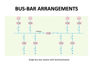
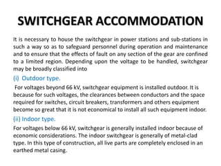
1
INTRODUCTION TO
SWITCHGEAR
Engr. Adnan Sayed
CONTENTS
 Switchgear
 Essential Features of Switchgear
 Switchgear Equipment
 Bus-Bar Arrangements
 Switchgear Accommodation
 Short-Circuit
 Short-Circuit Currents
INTRODUCTION
A switchgear essentially consists of switching and protecting
devices such as switches, fuses, circuit breakers, relays etc.
During normal operation, switchgear permits to switch on
or off generators, transmission lines, distributors and other
electrical equipment. On the other hand, when a failure
(e.g. short circuit) occurs on any part of power system, a
heavy current flows through the equipment, threatening
damage to the equipment and interruption of service to the
customers. However, the switchgear detects the fault and
disconnects the unhealthy section from the system. In this
way, switchgear protects the system from the damage and
ensures continuity of supply
SWITCHGEAR
The apparatus used for switching, controlling
and protecting the electrical circuits and
equipment is known as switchgear.
• The switchgear equipment is essentially
concerned with switching and interrupting
currents either under normal or abnormal
operating conditions.
ESSENTIAL FEATURES OF SWITCHGEAR
1. Complete reliability. The need for a reliable switchgear has
become of paramount importance. This is not surprising because switchgear
is added to the power system to improve the reliability. When fault occurs on
any part of the power system, the switchgear must operate to isolate the
faulty section from the remainder circuit.
2. Absolutely certain discrimination. When fault occurs on
any section of the power system, the switchgear must be able to discriminate
between the faulty section and the healthy section.
3. Quick operation. The switchgear must operate quickly so that no
damage is done to generators, transformers and other equipment by the
short-circuit currents.
4. Provision for manual control. A switchgear must have
provision for manual control. In case the electrical (or electronics) control
fails, the necessary operation can be carried out through manual control.
5. Provision for instruments. There must be provision for
instruments which may be required. These may be in the form of ammeter or
voltmeter .
SWITCHGEAR EQUIPMENT
1. SWITCHES.
A switch is a device which is used to open or close an electrical circuit in a
convenient way. It can be used under full-load or no-load conditions but it
cannot interrupt the fault currents.
The switches may be classified into.
(i) Air-break switch.
It is an air switch and is designed to open a circuit under load. Air-break
switches are generally used outdoor for circuits of medium capacity.
(ii) Isolator or disconnecting switch.
It is designed to open a circuit under no load. Its main purpose is to isolate
one portion of the circuit from the other and is not intended to be opened
while current is flowing in the line.
(iii) Oil switches.
As the name implies, the contacts of such switches are opened under oil. The
effect of oil is to cool and quench the arc that tends to form when the circuit
is opened.
SWITCHGEAR EQUIPMENT
2. FUSES.
A fuse is a short piece of wire or thin strip which melts when excessive current
flows through it for sufficient time.
It is worthwhile to note that a fuse performs both detection and interruption
functions.
3. CIRCUIT BREAKERS.
A circuit breaker is an equipment which can open or close a circuit under all
conditions viz. no load, full load and fault conditions. It is so designed that it
can be operated manually (or by remote control) under normal conditions
and automatically under fault conditions.
The circuit breaker essentially consists of moving and fixed contacts enclosed
in strong metal tank and immersed in oil, known as transformer oil.
SWITCHGEAR EQUIPMENT
4. Relays.
A relay is a device which detects the fault and supplies information to the
breaker for circuit interruption.
SWITCHGEAR EQUIPMENT
BUS-BAR ARRANGEMENTS
When a number of generators or feeders operating at
the same voltage have to be directly connected
electrically, bus-bars are used as the common electrical
component.
Bus-bars are copper rods or thin walled tubes and
operate at constant voltage
BUS-BAR ARRANGEMENTS
(1) Single Bus-bar System. The single busbar system has the
simplest design and is used for power stations. It is also used in small
outdoor stations having relatively few outgoing or incoming feeders and
lines.
The generators, outgoing lines and transformers are connected to the
bus-bar. Each generator and feeder is controlled by a circuit breaker. The
isolators permit to isolate generators, feeders and circuit breakers from the
bus-bar for maintenance.
Disadvantages:
(i) The bus-bar cannot be cleaned, repaired or tested without de-energising
the whole system.
(ii) If a fault occurs on the bus-bar itself, there is complete interruption of
supply.
(iii) Any fault on the system is fed by all the generating capacity, resulting in
very large fault currents.
BUS-BAR ARRANGEMENTS
Single Bus-bar System
BUS-BAR ARRANGEMENTS
(2) Single bus-bar system with Sectionalisation.
In large generating stations where several units are installed, it is a
common practice to sectionalise the bus so that fault on any section of
the bus-bar will not cause complete shut down.
Three principal advantages are claimed for this arrangement.
1. If a fault occurs on any section of the bus-bar, that section can be
isolated without affecting the supply to other sections.
2. if a fault occurs on any feeder, the fault current is much lower than
with unsectionalised bus-bar.
3. repairs and maintenance of any section of the bus-bar can be
carried out by de-energising that section only, eliminating the
possibility of complete shut-down.
BUS-BAR ARRANGEMENTS
Single bus-bar system with Sectionalisation
BUS-BAR ARRANGEMENTS
(3) Duplicate bus-bar system.
In large stations, it is important that breakdowns and maintenance should
interfere as little as possible with continuity of supply. In order to achieve this
objective, duplicate bus-bar system is used in important stations. Such a system
consists of two bus-bars, a “main bus-bar’’ and a “spare” bus-bar.
Each generator and feeder may be connected to either bus-bar with the help of
bus coupler which consists of a circuit breaker and isolators.
Advantages:
(i) If repair and maintenance it to be carried on the main bus, the supply need
not be interrupted as the entire load can be transferred to the spare bus.
(ii) The testing of feeder circuit breakers can be done by putting them on spare
bus-bar, thus keeping the main bus-bar undisturbed.
(iii) If a fault occurs on the bus-bar, the continuity of supply to the circuit can be
maintained by transferring it to the other bus-bar.
BUS-BAR ARRANGEMENTS
Duplicate bus-bar system
SWITCHGEAR ACCOMMODATION
It is necessary to house the switchgear in power stations and sub-stations in
such a way so as to safeguard personnel during operation and maintenance
and to ensure that the effects of fault on any section of the gear are confined
to a limited region. Depending upon the voltage to be handled, switchgear
may be broadly classified into
(i) Outdoor type.
For voltages beyond 66 kV, switchgear equipment is installed outdoor. It is
because for such voltages, the clearances between conductors and the space
required for switches, circuit breakers, transformers and others equipment
become so great that it is not economical to install all such equipment indoor.
(ii) Indoor type.
For voltages below 66 kV, switchgear is generally installed indoor because of
economic considerations. The indoor switchgear is generally of metal-clad
type. In this type of construction, all live parts are completely enclosed in an
earthed metal casing.
SHORT-CIRCUIT
Whenever a fault occurs on a network such that a large current flows in one or
more phases, a short-circuit is said to have occurred.
When a short circuit occurs, a heavy current called short circuit current flows
through the circuit.
Consider a single phase generator of voltage V and internal impedance Zi is
supplying to a load Z. Under normal conditions, the current in the circuit is
limited by load impedance Z. However, if the load terminals get shorted due
to any reason, the circuit impedance is reduced to a very low value ; being Zi
in this case. As Zi is very small, therefore, a large current flows through the
circuit. This is called short-circuit current.
CAUSES OF SHORT-CIRCUIT.
A short circuit in the power system is the result of some kind of abnormal
conditions in the system. It may be caused due to internal and/or external
effects.
(i) Internal effects are caused by breakdown of equipment or transmission
lines, from deterioration of insulation in a generator, transformer etc.
Such troubles may be due to ageing of insulation, inadequate design or
improper installation.
(ii) External effects causing short circuit include insulation failure due to
lightning surges, overloading of equipment causing excessive heating;
mechanical damage by public etc.
SHORT-CIRCUIT CURRENTS
Most of the failures on the power system lead to short-circuit fault and
cause heavy current to flow in the system. The calculations of these
short-circuit currents are important for the following reasons :
(i) A short-circuit on the power system is cleared by a circuit breaker
or a fuse. It is necessary, therefore, to know the maximum
possible values of short-circuit current so that switchgear of
suitable rating may be installed to interrupt them.
(ii) The magnitude of short-circuit current determines the setting and
sometimes the types and location of protective system.
(iii) The magnitude of short-circuit current determines the size of the
protective reactors which must be inserted in the system so that
the circuit breaker is able to withstand the fault current.
(iv) The calculation of short-circuit currents enables us to make
proper selection of the associated apparatus (e.g. bus-bars,
current transformers etc.) so that they can withstand the forces
that arise due to the occurrence of short circuits.
Thank You…

Introduction to switchgear

  • 1.
  • 2.
  • 3.
    CONTENTS  Switchgear  EssentialFeatures of Switchgear  Switchgear Equipment  Bus-Bar Arrangements  Switchgear Accommodation  Short-Circuit  Short-Circuit Currents
  • 4.
    INTRODUCTION A switchgear essentiallyconsists of switching and protecting devices such as switches, fuses, circuit breakers, relays etc. During normal operation, switchgear permits to switch on or off generators, transmission lines, distributors and other electrical equipment. On the other hand, when a failure (e.g. short circuit) occurs on any part of power system, a heavy current flows through the equipment, threatening damage to the equipment and interruption of service to the customers. However, the switchgear detects the fault and disconnects the unhealthy section from the system. In this way, switchgear protects the system from the damage and ensures continuity of supply
  • 5.
    SWITCHGEAR The apparatus usedfor switching, controlling and protecting the electrical circuits and equipment is known as switchgear. • The switchgear equipment is essentially concerned with switching and interrupting currents either under normal or abnormal operating conditions.
  • 6.
    ESSENTIAL FEATURES OFSWITCHGEAR 1. Complete reliability. The need for a reliable switchgear has become of paramount importance. This is not surprising because switchgear is added to the power system to improve the reliability. When fault occurs on any part of the power system, the switchgear must operate to isolate the faulty section from the remainder circuit. 2. Absolutely certain discrimination. When fault occurs on any section of the power system, the switchgear must be able to discriminate between the faulty section and the healthy section. 3. Quick operation. The switchgear must operate quickly so that no damage is done to generators, transformers and other equipment by the short-circuit currents. 4. Provision for manual control. A switchgear must have provision for manual control. In case the electrical (or electronics) control fails, the necessary operation can be carried out through manual control. 5. Provision for instruments. There must be provision for instruments which may be required. These may be in the form of ammeter or voltmeter .
  • 7.
    SWITCHGEAR EQUIPMENT 1. SWITCHES. Aswitch is a device which is used to open or close an electrical circuit in a convenient way. It can be used under full-load or no-load conditions but it cannot interrupt the fault currents. The switches may be classified into. (i) Air-break switch. It is an air switch and is designed to open a circuit under load. Air-break switches are generally used outdoor for circuits of medium capacity. (ii) Isolator or disconnecting switch. It is designed to open a circuit under no load. Its main purpose is to isolate one portion of the circuit from the other and is not intended to be opened while current is flowing in the line. (iii) Oil switches. As the name implies, the contacts of such switches are opened under oil. The effect of oil is to cool and quench the arc that tends to form when the circuit is opened.
  • 8.
    SWITCHGEAR EQUIPMENT 2. FUSES. Afuse is a short piece of wire or thin strip which melts when excessive current flows through it for sufficient time. It is worthwhile to note that a fuse performs both detection and interruption functions. 3. CIRCUIT BREAKERS. A circuit breaker is an equipment which can open or close a circuit under all conditions viz. no load, full load and fault conditions. It is so designed that it can be operated manually (or by remote control) under normal conditions and automatically under fault conditions. The circuit breaker essentially consists of moving and fixed contacts enclosed in strong metal tank and immersed in oil, known as transformer oil.
  • 9.
    SWITCHGEAR EQUIPMENT 4. Relays. Arelay is a device which detects the fault and supplies information to the breaker for circuit interruption.
  • 10.
  • 11.
    BUS-BAR ARRANGEMENTS When anumber of generators or feeders operating at the same voltage have to be directly connected electrically, bus-bars are used as the common electrical component. Bus-bars are copper rods or thin walled tubes and operate at constant voltage
  • 12.
    BUS-BAR ARRANGEMENTS (1) SingleBus-bar System. The single busbar system has the simplest design and is used for power stations. It is also used in small outdoor stations having relatively few outgoing or incoming feeders and lines. The generators, outgoing lines and transformers are connected to the bus-bar. Each generator and feeder is controlled by a circuit breaker. The isolators permit to isolate generators, feeders and circuit breakers from the bus-bar for maintenance. Disadvantages: (i) The bus-bar cannot be cleaned, repaired or tested without de-energising the whole system. (ii) If a fault occurs on the bus-bar itself, there is complete interruption of supply. (iii) Any fault on the system is fed by all the generating capacity, resulting in very large fault currents.
  • 13.
  • 14.
    BUS-BAR ARRANGEMENTS (2) Singlebus-bar system with Sectionalisation. In large generating stations where several units are installed, it is a common practice to sectionalise the bus so that fault on any section of the bus-bar will not cause complete shut down. Three principal advantages are claimed for this arrangement. 1. If a fault occurs on any section of the bus-bar, that section can be isolated without affecting the supply to other sections. 2. if a fault occurs on any feeder, the fault current is much lower than with unsectionalised bus-bar. 3. repairs and maintenance of any section of the bus-bar can be carried out by de-energising that section only, eliminating the possibility of complete shut-down.
  • 15.
    BUS-BAR ARRANGEMENTS Single bus-barsystem with Sectionalisation
  • 16.
    BUS-BAR ARRANGEMENTS (3) Duplicatebus-bar system. In large stations, it is important that breakdowns and maintenance should interfere as little as possible with continuity of supply. In order to achieve this objective, duplicate bus-bar system is used in important stations. Such a system consists of two bus-bars, a “main bus-bar’’ and a “spare” bus-bar. Each generator and feeder may be connected to either bus-bar with the help of bus coupler which consists of a circuit breaker and isolators. Advantages: (i) If repair and maintenance it to be carried on the main bus, the supply need not be interrupted as the entire load can be transferred to the spare bus. (ii) The testing of feeder circuit breakers can be done by putting them on spare bus-bar, thus keeping the main bus-bar undisturbed. (iii) If a fault occurs on the bus-bar, the continuity of supply to the circuit can be maintained by transferring it to the other bus-bar.
  • 17.
  • 18.
    SWITCHGEAR ACCOMMODATION It isnecessary to house the switchgear in power stations and sub-stations in such a way so as to safeguard personnel during operation and maintenance and to ensure that the effects of fault on any section of the gear are confined to a limited region. Depending upon the voltage to be handled, switchgear may be broadly classified into (i) Outdoor type. For voltages beyond 66 kV, switchgear equipment is installed outdoor. It is because for such voltages, the clearances between conductors and the space required for switches, circuit breakers, transformers and others equipment become so great that it is not economical to install all such equipment indoor. (ii) Indoor type. For voltages below 66 kV, switchgear is generally installed indoor because of economic considerations. The indoor switchgear is generally of metal-clad type. In this type of construction, all live parts are completely enclosed in an earthed metal casing.
  • 19.
    SHORT-CIRCUIT Whenever a faultoccurs on a network such that a large current flows in one or more phases, a short-circuit is said to have occurred. When a short circuit occurs, a heavy current called short circuit current flows through the circuit. Consider a single phase generator of voltage V and internal impedance Zi is supplying to a load Z. Under normal conditions, the current in the circuit is limited by load impedance Z. However, if the load terminals get shorted due to any reason, the circuit impedance is reduced to a very low value ; being Zi in this case. As Zi is very small, therefore, a large current flows through the circuit. This is called short-circuit current.
  • 20.
    CAUSES OF SHORT-CIRCUIT. Ashort circuit in the power system is the result of some kind of abnormal conditions in the system. It may be caused due to internal and/or external effects. (i) Internal effects are caused by breakdown of equipment or transmission lines, from deterioration of insulation in a generator, transformer etc. Such troubles may be due to ageing of insulation, inadequate design or improper installation. (ii) External effects causing short circuit include insulation failure due to lightning surges, overloading of equipment causing excessive heating; mechanical damage by public etc.
  • 21.
    SHORT-CIRCUIT CURRENTS Most ofthe failures on the power system lead to short-circuit fault and cause heavy current to flow in the system. The calculations of these short-circuit currents are important for the following reasons : (i) A short-circuit on the power system is cleared by a circuit breaker or a fuse. It is necessary, therefore, to know the maximum possible values of short-circuit current so that switchgear of suitable rating may be installed to interrupt them. (ii) The magnitude of short-circuit current determines the setting and sometimes the types and location of protective system. (iii) The magnitude of short-circuit current determines the size of the protective reactors which must be inserted in the system so that the circuit breaker is able to withstand the fault current. (iv) The calculation of short-circuit currents enables us to make proper selection of the associated apparatus (e.g. bus-bars, current transformers etc.) so that they can withstand the forces that arise due to the occurrence of short circuits.
  • 22.