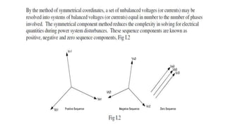
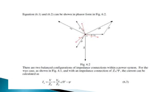
Positive, negative ,zero
sequence
 The electrical power system normally operates
in a balanced three-phase sinusoidal steady-
state
mode. However, there are certain situations
that can cause unbalanced operations.
 The most severe of these would be a fault or
short circuit. Examples may include a tree in
contact with a conductor, a lightning strike, or
downed power line.
 The purpose of this ..is to explain symmetrical
components and review complex algebra in order
to manipulate the components.
 Knowledge of symmetrical components is
important in
performing mathematical calculations and
understanding system faults.
 It is also valuable in analyzing faults and how
they apply to relay operations.
2.PROPERTIES OF PHASORS
 A vector is a mathematical quantity that has both a
magnitude and direction. Many quantities in the power
industry are vector quantities. The term phasor is used
within the steady state alternating linear system. It is used
to avoid confusion with spatial vectors: the angular
position of the phasor represents position in time, not
space. In this document, phasors will be used to document
various ac voltages, currents and impedances.

 A phasor quantity or phasor, provides information about
not only the magnitude but also the direction or angle of
the quantity. When using a compass and giving directions
to a house, from a given location, a distance and direction
must be provided. For example one could say that a house
is 10 miles at an angle of 75 degrees (rotated in a
clockwise direction from North) from where I am standing.
 Just as we don’t say the other house is -10 miles
away, the magnitude of the phasor is always a
positive, or rather the absolute value of the
“length of the phasor.” Therefore giving
directions in the opposite direction, one could
say that a house is 10 miles at an angle of 255
degrees. The quantity could be a potential,
current, watts, etc.

Phasors are written in polar form as
Y = Y q.....................2.1
= Y cosq + j Y sinq........2.2
where Y is the phasor, Y is the amplitude, magnitude or absolute value and
q is the phase angle
or argument. Polar numbers are written with the magnitude followed by the
 symbol to
indicate angle, followed by the phase angle expressed in degrees. For
example
Z = 11090o .
This would be read as 110 at an angle of 90 degrees. The rectangular form
is easily produced by applying Eq. (2.2)
The phasor can be represented graphically as we have
demonstrated in Fig. 1.1, with the real components coinciding with
the x axis.
When multiplying two phasors it is best to have the phasor written in
the polar form. The magnitudes are multiplied together and the
phase angles are added together.
Division, which is the inverse of multiplication, can be accomplished
in a similar manner.
In division the magnitudes are divided and the phase angle in the
denominator is subtracted from the phase angle in the numerator.
Recall the operator j. In polar form, j = 190o . Multiplying by j
has the effect of rotating a phasor 90o without affecting the
magnitude.
Table 3.1 - Properties of the vector j
1 = 1.0 + j0.0 j = 190o
j 2 = 1180o = -1
j3 = 1270o = - j
- j = 1 - 90o
3.The j and a operator
Example 3.1
Compute jR where
Solution
R = 1060o .
jR = 190o (1060o )
= 10150o
Notice that multiplication by the j operator rotated the
Phasor R by 90o , but did not change the magnitude. Refer
to Fig. 3.1
a.R
R
jR
 In many engineering situations it is useful to
scale, or normalize, dimensioned quantities. This
is commonly done in power system analysis. The
standard method used is referred to as the per-
unit system. Historically, this was done to
simplify numerical calculations that were made
by hand. Although this advantage is eliminated
by the calculator, other advantages remain.
 Device parameters tend to fall into a relatively
narrow range, making erroneous values
conspicuous.
 Using this method all quantities are expressed as
ratios of some base value or values.
 The per-unit equivalent impedance of any
transformer is the same when referred to either
the primary or the secondary side.
 The per-unit impedance of a transformer in a
three-phase system is the same regardless of the
type of winding connections (wye-delta, delta-
wye, wye-wye, or delta-delta).
 The per-unit method is independent of voltage
changes and phase shifts through transformers
where the base voltages in the winding are
proportional to the number of turns in the
windings.
 The per-unit system is simply a scaling method.
The basic per-unit scaling equation is
per - unit = actual _ value/base _ value
 The base value always has the same units as the
actual value, forcing the per-unit value to be
dimensionless. The base value is always a real
number, whereas the actual value may be
complex. The subscript pu will indicate a per-
unit value. The subscript base will indicate a
base value, and no subscript will indicate an
actual value such as Amperes, Ohms, or Volts.

 The first step in using per-unit is to select the base(s)
for the system.
 Sbase = power base, in VA. Although in principle Sbase
may be selected arbitrarily, in practice it is typically
chosen to be 100 MVA.
 Vbase = voltage base in V. Although in principle Vbase
is also arbitrary, in practice Vbase is equal to the
nominal line-to-line voltage. The term nominal
means the value at which the system was designed to
operate under normal balanced conditions.

 From Eq. (4.5) it follows that the base power equation
for a three-phase system is:
 The electrical power system operates in a balanced
three-phase sinusoidal operation. When a tree
contacts a line, a lightning bolt strikes a conductor or
two conductors swing into each other we call this a
fault, or a fault on the line. When this occurs the
system goes from a balanced condition to an
unbalanced condition. In order to properly set the
protective relays, it is necessary to calculate currents
and voltages in the system under such unbalanced
operating conditions.
described how symmetrical components can transform an
unbalanced condition into symmetrical components, compute
the system response by straight forward circuit analysis on
simple circuit models, and transform the results back into
original phase variables. When a short circuit fault occurs the
result can be a set of unbalanced voltages and currents. The
theory of symmetrical components resolves any set of
unbalanced voltages or currents into three sets of
symmetrical balanced phasors.
These are known as positive, negative and zero sequence
components. Fig. 7.1 shows balanced and unbalanced
systems

THANK YOU..................
 DO SMART ..........LEARN SMART

Symmetrical components......

  • 1.
  • 2.
     The electricalpower system normally operates in a balanced three-phase sinusoidal steady- state mode. However, there are certain situations that can cause unbalanced operations.  The most severe of these would be a fault or short circuit. Examples may include a tree in contact with a conductor, a lightning strike, or downed power line.
  • 5.
     The purposeof this ..is to explain symmetrical components and review complex algebra in order to manipulate the components.  Knowledge of symmetrical components is important in performing mathematical calculations and understanding system faults.  It is also valuable in analyzing faults and how they apply to relay operations.
  • 7.
    2.PROPERTIES OF PHASORS A vector is a mathematical quantity that has both a magnitude and direction. Many quantities in the power industry are vector quantities. The term phasor is used within the steady state alternating linear system. It is used to avoid confusion with spatial vectors: the angular position of the phasor represents position in time, not space. In this document, phasors will be used to document various ac voltages, currents and impedances.   A phasor quantity or phasor, provides information about not only the magnitude but also the direction or angle of the quantity. When using a compass and giving directions to a house, from a given location, a distance and direction must be provided. For example one could say that a house is 10 miles at an angle of 75 degrees (rotated in a clockwise direction from North) from where I am standing.
  • 8.
     Just aswe don’t say the other house is -10 miles away, the magnitude of the phasor is always a positive, or rather the absolute value of the “length of the phasor.” Therefore giving directions in the opposite direction, one could say that a house is 10 miles at an angle of 255 degrees. The quantity could be a potential, current, watts, etc. 
  • 9.
    Phasors are writtenin polar form as Y = Y q.....................2.1 = Y cosq + j Y sinq........2.2 where Y is the phasor, Y is the amplitude, magnitude or absolute value and q is the phase angle or argument. Polar numbers are written with the magnitude followed by the  symbol to indicate angle, followed by the phase angle expressed in degrees. For example Z = 11090o . This would be read as 110 at an angle of 90 degrees. The rectangular form is easily produced by applying Eq. (2.2)
  • 10.
    The phasor canbe represented graphically as we have demonstrated in Fig. 1.1, with the real components coinciding with the x axis. When multiplying two phasors it is best to have the phasor written in the polar form. The magnitudes are multiplied together and the phase angles are added together. Division, which is the inverse of multiplication, can be accomplished in a similar manner. In division the magnitudes are divided and the phase angle in the denominator is subtracted from the phase angle in the numerator.
  • 11.
    Recall the operatorj. In polar form, j = 190o . Multiplying by j has the effect of rotating a phasor 90o without affecting the magnitude. Table 3.1 - Properties of the vector j 1 = 1.0 + j0.0 j = 190o j 2 = 1180o = -1 j3 = 1270o = - j - j = 1 - 90o 3.The j and a operator
  • 12.
    Example 3.1 Compute jRwhere Solution R = 1060o . jR = 190o (1060o ) = 10150o Notice that multiplication by the j operator rotated the Phasor R by 90o , but did not change the magnitude. Refer to Fig. 3.1 a.R R jR
  • 19.
     In manyengineering situations it is useful to scale, or normalize, dimensioned quantities. This is commonly done in power system analysis. The standard method used is referred to as the per- unit system. Historically, this was done to simplify numerical calculations that were made by hand. Although this advantage is eliminated by the calculator, other advantages remain.  Device parameters tend to fall into a relatively narrow range, making erroneous values conspicuous.  Using this method all quantities are expressed as ratios of some base value or values.
  • 20.
     The per-unitequivalent impedance of any transformer is the same when referred to either the primary or the secondary side.  The per-unit impedance of a transformer in a three-phase system is the same regardless of the type of winding connections (wye-delta, delta- wye, wye-wye, or delta-delta).  The per-unit method is independent of voltage changes and phase shifts through transformers where the base voltages in the winding are proportional to the number of turns in the windings.
  • 21.
     The per-unitsystem is simply a scaling method. The basic per-unit scaling equation is per - unit = actual _ value/base _ value  The base value always has the same units as the actual value, forcing the per-unit value to be dimensionless. The base value is always a real number, whereas the actual value may be complex. The subscript pu will indicate a per- unit value. The subscript base will indicate a base value, and no subscript will indicate an actual value such as Amperes, Ohms, or Volts. 
  • 22.
     The firststep in using per-unit is to select the base(s) for the system.  Sbase = power base, in VA. Although in principle Sbase may be selected arbitrarily, in practice it is typically chosen to be 100 MVA.  Vbase = voltage base in V. Although in principle Vbase is also arbitrary, in practice Vbase is equal to the nominal line-to-line voltage. The term nominal means the value at which the system was designed to operate under normal balanced conditions.   From Eq. (4.5) it follows that the base power equation for a three-phase system is:
  • 35.
     The electricalpower system operates in a balanced three-phase sinusoidal operation. When a tree contacts a line, a lightning bolt strikes a conductor or two conductors swing into each other we call this a fault, or a fault on the line. When this occurs the system goes from a balanced condition to an unbalanced condition. In order to properly set the protective relays, it is necessary to calculate currents and voltages in the system under such unbalanced operating conditions.
  • 36.
    described how symmetricalcomponents can transform an unbalanced condition into symmetrical components, compute the system response by straight forward circuit analysis on simple circuit models, and transform the results back into original phase variables. When a short circuit fault occurs the result can be a set of unbalanced voltages and currents. The theory of symmetrical components resolves any set of unbalanced voltages or currents into three sets of symmetrical balanced phasors. These are known as positive, negative and zero sequence components. Fig. 7.1 shows balanced and unbalanced systems
  • 53.
     THANK YOU..................  DOSMART ..........LEARN SMART