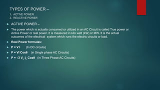
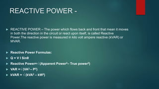
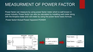
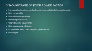
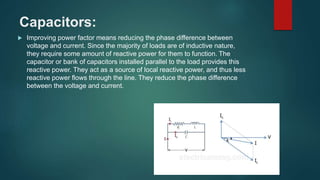
THE POWER
FACTOR
PRESENTED BY – AMIT MAHOLIYA
DEPARTMENT – ELECTRICAL (B.TECH 3RD SEM.)
SID - 55141
OBJECTIVES -
 DEFINATION OF POWER FACTOR
 MEASURMENT OF POWER FACTOR
 DISADVANTAGES OF POOR POWER FACTOR
 IMPROVEMENT OF THE POWER FACTOR
 VARIOUS METHODS TO IMPROVE THE POWER FACTOR
 ADVANTAGE OF HIGH POWER FACTOR
 CONCLUSION
DEFINATION OF POWER
FACTOR
 POWER FACTOR – The ratio between actual power to the apparent power is known as power
factor or the utilization of active power is known as power factor.
 Power factor is also defined as the cosine of phase angle phi( ) between voltage (V) and the
current(I).
 Means P.F. = cos
 Power factor is denoted by P.F.
 Power factor = Actual power / Apparent power
 P.F. = KW/KVA
TYPES OF POWER –
1. ACTIVE POWER
2. REACTIVE POWER
 ACTIVE POWER –
 The power which is actually consumed or utilized in an AC Circuit is called True power or
Active Power or real power. It is measured in kilo watt (kW) or MW. It is the actual
outcomes of the electrical system which runs the electric circuits or load.
 Real Power formulas:
 P = V I (In DC circuits)
 P = VI Cosθ (in Single phase AC Circuits)
 P = √3 VL IL Cosθ (in Three Phase AC Circuits)
REACTIVE POWER -
 REACTIVE POWER – The power which flows back and front that mean it moves
in both the direction in the circuit or react upon itself, is called Reactive
Power.The reactive power is measured in kilo volt ampere reactive (kVAR) or
MVAR.
 Reactive Power Formulas:
 Q = V I Sinθ
 Reactive Power=√ (Apparent Power2– True power2)
 VAR =√ (VA2 – P2)
 kVAR = √ (kVA2 – kW2)
APPARENT POWER -
 APPARENT POWER – The product of root mean square (RMS) value of
voltage and current is known as Apparent Power. This power is measured in
kVA or MVA.
 Apparent Power Formulas:
 S = V I
 Apparent Power = √ (True power2 + Reactive Power2)
 kVA = √kW2 + kVAR2
POWER FACTOR FOR DIFFERENT TYPES OF LOADS -
 RESISTIVE LOAD – for purely resistive load power factor is unity because the phase angle between
voltage and current is zero. Ex- Bulb,heater,iron etc.
 P.F. = cos => = 0 => cos0 = 1
 So, power factor is 1 or unity for a purely resistive load
 INDUCTIVE LOAD - for purely inductive load power factor is lagging power factor because in inductive
load current is lag with voltage by 90 degree phase angle.Ex.- transformer,fan etc.
 CAPACITIVE LOAD – for purely capacitive load power factor is leading power factor because in capacitive
load current leads with voltage by 90 degree phase angle. Ex.- condensor.
MEASURMENT OF POWER FACTOR
Power factor can measure by using power factor meter which is well known in
power industry. Power factor can also be calculated by installing watt meter along
with the Ampere meter and volt meter by using the power factor basic formula.
Power factor=Actual Power/ Apparent POWER
DISADVANTAAGE OF POOR POWER FACTOR
 Increases heating losses in the transformers and distribution equipments.
 Reduce plant life.
 Unstabilise voltage levels.
 Increase power losses.
 Upgrade costly equipments.
 Decrease energy efficiency.
 Increase electricity costs by paying power factor
 surcharges.
HOW TO IMPROVE THE POWER FACTOR?
 Power factor decreases with the installation of non resistive loads such as
induction motors, Transformers. Lighting ballasts and electronic
equipments. Power factors can be corrected by using capacitors. These
are rated in electrical units called VAR or KVAR.One VAR is equivalent to
one volt of reactive power. VAR then are units of measurement for
indicating just how much reactive power the capacitor will supply.
HOW TO IMPROVE THE POWER FACTOR
- As reactive power is usually measured in thousands the letter K is used for
thousand. the capacitor KVAR rating then shows how much reactive power
the capacitor will supply. Each unit of the capacitor's KVAR will decrease the
inductive reactive power demand.
- Most loads on an electrical distribution system fall into one of three
categories; resistive, inductive or capacitive. In most plant, the most common
is likely to be inductive.Typical examples of this include transformers,
fluorescent lighting and AC induction motors. Most inductive loads use a
conductive coil winding to produce an electromagnetic field, allowing the
motor to function.
HOW TO IMPROVE THE POWEER
FACTOR
 The amount of Power Capacitor KVAR required to correct A system to a
desired Power Factor level is the difference between the amount of KVAR
in the uncorrected system and the amount of desired KVAR in the
corrected system. The most efficient location for power factor capacitors is
at the load. Capacitors work from the point of installation back to the
generating source. Individual motor correction is not always practical,
sometimes it is more practical to connect larger capacitors on the
distribution bus or install an automatic system at the incoming service
along with fixed capacitors at the load.
POWER FACTOR CORRECTION METHODS
 Static Var Compensator(SVC)
 Fixed Capcitors
 Switch Capacitors
 Synchronous Condensors
 Static Synchronous Compensator(STATCOM)
 Modulated power filter capacitor compensator
STATIC VAR COMPENSATOR (SVC)
 The Static Var Compensator (SVC) is a shunt device of the Flexible AC
Transmission Systems (FACTS) family using power electronics to control
power flow and improve transient stability on power grids . The SVC regulates
voltage at its terminals by controlling the amount of reactive power injected
into or absorbed from the power system. When system voltage is low, the SVC
generates reactive power (SVC capacitive). When system voltage is high, it
absorbs reactive power The variation of reactive power is performed by
switching
 three-phase capacitor banks and inductor banks connected on the secondary
side of a coupling transformer. Each capacitor bank is switched on and off by
three thyristor switches (Thyristor Switched Capacitor or TSC). Reactors are
either switched on-off (Thyristor Switched Reactor or TSR) or phase-controlled
(Thyristor Controlled Reactor or TCR) or (SVC) inductive.
Capacitors:
 Improving power factor means reducing the phase difference between
voltage and current. Since the majority of loads are of inductive nature,
they require some amount of reactive power for them to function. The
capacitor or bank of capacitors installed parallel to the load provides this
reactive power. They act as a source of local reactive power, and thus less
reactive power flows through the line. They reduce the phase difference
between the voltage and current.
Synchronous Condenser:
 They are 3 phase synchronous motor with no load attached to its shaft.
The synchronous motor has the characteristics of operating under any
power factor leading, lagging or unity depending upon the excitation. For
inductive loads, a synchronous condenser is connected towards load side
and is overexcited. Synchronous condenser makes it behave like a
capacitor. It draws the lagging current from the supply or supplies the
reactive power.

Phase Advancer:
 This is an ac exciter mainly used to improve power factor of induction motor.
They are mounted on the shaft of the motor and connected to the rotor circuit
of the motor. It improves the power factor by providing the exciting ampere
turns to produce required flux at slip frequency. Further, if ampere-turns
increase, it can be made to operate at leading power factor.
ADVANTAGES OF HIGH POWER FACTOR
 Reduced copper losses.
 Smaller conductor size.
 Improved voltage regulation.
 Increased system capacity.
 Less energy bill
CONCLUSION
 BYobserving all aspects of the power factor it is clear that power factor is the
most significant part for the utility Company as well as for the consumer.
Utility company rid of from the power losses while the consumer free from low
power factor penalty charges. By installing suitably sized power capacitors
into the circuit the Power Factor is improved and the value becomes nearer to
1 thus minimising line losses and improving the efficiency of a plant.
THANK YOU
THANK YOU

THE POWER FACTOR

  • 1.
    THE POWER FACTOR PRESENTED BY– AMIT MAHOLIYA DEPARTMENT – ELECTRICAL (B.TECH 3RD SEM.) SID - 55141
  • 2.
    OBJECTIVES -  DEFINATIONOF POWER FACTOR  MEASURMENT OF POWER FACTOR  DISADVANTAGES OF POOR POWER FACTOR  IMPROVEMENT OF THE POWER FACTOR  VARIOUS METHODS TO IMPROVE THE POWER FACTOR  ADVANTAGE OF HIGH POWER FACTOR  CONCLUSION
  • 3.
    DEFINATION OF POWER FACTOR POWER FACTOR – The ratio between actual power to the apparent power is known as power factor or the utilization of active power is known as power factor.  Power factor is also defined as the cosine of phase angle phi( ) between voltage (V) and the current(I).  Means P.F. = cos  Power factor is denoted by P.F.  Power factor = Actual power / Apparent power  P.F. = KW/KVA
  • 4.
    TYPES OF POWER– 1. ACTIVE POWER 2. REACTIVE POWER  ACTIVE POWER –  The power which is actually consumed or utilized in an AC Circuit is called True power or Active Power or real power. It is measured in kilo watt (kW) or MW. It is the actual outcomes of the electrical system which runs the electric circuits or load.  Real Power formulas:  P = V I (In DC circuits)  P = VI Cosθ (in Single phase AC Circuits)  P = √3 VL IL Cosθ (in Three Phase AC Circuits)
  • 5.
    REACTIVE POWER - REACTIVE POWER – The power which flows back and front that mean it moves in both the direction in the circuit or react upon itself, is called Reactive Power.The reactive power is measured in kilo volt ampere reactive (kVAR) or MVAR.  Reactive Power Formulas:  Q = V I Sinθ  Reactive Power=√ (Apparent Power2– True power2)  VAR =√ (VA2 – P2)  kVAR = √ (kVA2 – kW2)
  • 6.
    APPARENT POWER - APPARENT POWER – The product of root mean square (RMS) value of voltage and current is known as Apparent Power. This power is measured in kVA or MVA.  Apparent Power Formulas:  S = V I  Apparent Power = √ (True power2 + Reactive Power2)  kVA = √kW2 + kVAR2
  • 7.
    POWER FACTOR FORDIFFERENT TYPES OF LOADS -  RESISTIVE LOAD – for purely resistive load power factor is unity because the phase angle between voltage and current is zero. Ex- Bulb,heater,iron etc.  P.F. = cos => = 0 => cos0 = 1  So, power factor is 1 or unity for a purely resistive load  INDUCTIVE LOAD - for purely inductive load power factor is lagging power factor because in inductive load current is lag with voltage by 90 degree phase angle.Ex.- transformer,fan etc.  CAPACITIVE LOAD – for purely capacitive load power factor is leading power factor because in capacitive load current leads with voltage by 90 degree phase angle. Ex.- condensor.
  • 8.
    MEASURMENT OF POWERFACTOR Power factor can measure by using power factor meter which is well known in power industry. Power factor can also be calculated by installing watt meter along with the Ampere meter and volt meter by using the power factor basic formula. Power factor=Actual Power/ Apparent POWER
  • 9.
    DISADVANTAAGE OF POORPOWER FACTOR  Increases heating losses in the transformers and distribution equipments.  Reduce plant life.  Unstabilise voltage levels.  Increase power losses.  Upgrade costly equipments.  Decrease energy efficiency.  Increase electricity costs by paying power factor  surcharges.
  • 10.
    HOW TO IMPROVETHE POWER FACTOR?  Power factor decreases with the installation of non resistive loads such as induction motors, Transformers. Lighting ballasts and electronic equipments. Power factors can be corrected by using capacitors. These are rated in electrical units called VAR or KVAR.One VAR is equivalent to one volt of reactive power. VAR then are units of measurement for indicating just how much reactive power the capacitor will supply.
  • 11.
    HOW TO IMPROVETHE POWER FACTOR - As reactive power is usually measured in thousands the letter K is used for thousand. the capacitor KVAR rating then shows how much reactive power the capacitor will supply. Each unit of the capacitor's KVAR will decrease the inductive reactive power demand. - Most loads on an electrical distribution system fall into one of three categories; resistive, inductive or capacitive. In most plant, the most common is likely to be inductive.Typical examples of this include transformers, fluorescent lighting and AC induction motors. Most inductive loads use a conductive coil winding to produce an electromagnetic field, allowing the motor to function.
  • 12.
    HOW TO IMPROVETHE POWEER FACTOR  The amount of Power Capacitor KVAR required to correct A system to a desired Power Factor level is the difference between the amount of KVAR in the uncorrected system and the amount of desired KVAR in the corrected system. The most efficient location for power factor capacitors is at the load. Capacitors work from the point of installation back to the generating source. Individual motor correction is not always practical, sometimes it is more practical to connect larger capacitors on the distribution bus or install an automatic system at the incoming service along with fixed capacitors at the load.
  • 13.
    POWER FACTOR CORRECTIONMETHODS  Static Var Compensator(SVC)  Fixed Capcitors  Switch Capacitors  Synchronous Condensors  Static Synchronous Compensator(STATCOM)  Modulated power filter capacitor compensator
  • 14.
    STATIC VAR COMPENSATOR(SVC)  The Static Var Compensator (SVC) is a shunt device of the Flexible AC Transmission Systems (FACTS) family using power electronics to control power flow and improve transient stability on power grids . The SVC regulates voltage at its terminals by controlling the amount of reactive power injected into or absorbed from the power system. When system voltage is low, the SVC generates reactive power (SVC capacitive). When system voltage is high, it absorbs reactive power The variation of reactive power is performed by switching  three-phase capacitor banks and inductor banks connected on the secondary side of a coupling transformer. Each capacitor bank is switched on and off by three thyristor switches (Thyristor Switched Capacitor or TSC). Reactors are either switched on-off (Thyristor Switched Reactor or TSR) or phase-controlled (Thyristor Controlled Reactor or TCR) or (SVC) inductive.
  • 15.
    Capacitors:  Improving powerfactor means reducing the phase difference between voltage and current. Since the majority of loads are of inductive nature, they require some amount of reactive power for them to function. The capacitor or bank of capacitors installed parallel to the load provides this reactive power. They act as a source of local reactive power, and thus less reactive power flows through the line. They reduce the phase difference between the voltage and current.
  • 16.
    Synchronous Condenser:  Theyare 3 phase synchronous motor with no load attached to its shaft. The synchronous motor has the characteristics of operating under any power factor leading, lagging or unity depending upon the excitation. For inductive loads, a synchronous condenser is connected towards load side and is overexcited. Synchronous condenser makes it behave like a capacitor. It draws the lagging current from the supply or supplies the reactive power. 
  • 17.
    Phase Advancer:  Thisis an ac exciter mainly used to improve power factor of induction motor. They are mounted on the shaft of the motor and connected to the rotor circuit of the motor. It improves the power factor by providing the exciting ampere turns to produce required flux at slip frequency. Further, if ampere-turns increase, it can be made to operate at leading power factor.
  • 18.
    ADVANTAGES OF HIGHPOWER FACTOR  Reduced copper losses.  Smaller conductor size.  Improved voltage regulation.  Increased system capacity.  Less energy bill
  • 19.
    CONCLUSION  BYobserving allaspects of the power factor it is clear that power factor is the most significant part for the utility Company as well as for the consumer. Utility company rid of from the power losses while the consumer free from low power factor penalty charges. By installing suitably sized power capacitors into the circuit the Power Factor is improved and the value becomes nearer to 1 thus minimising line losses and improving the efficiency of a plant.
  • 20.