Downloaded 9,016 times

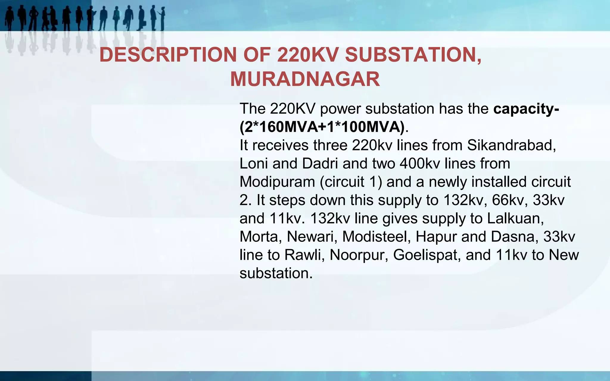
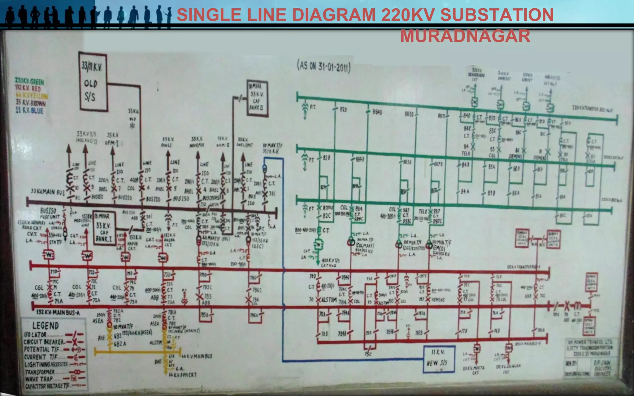
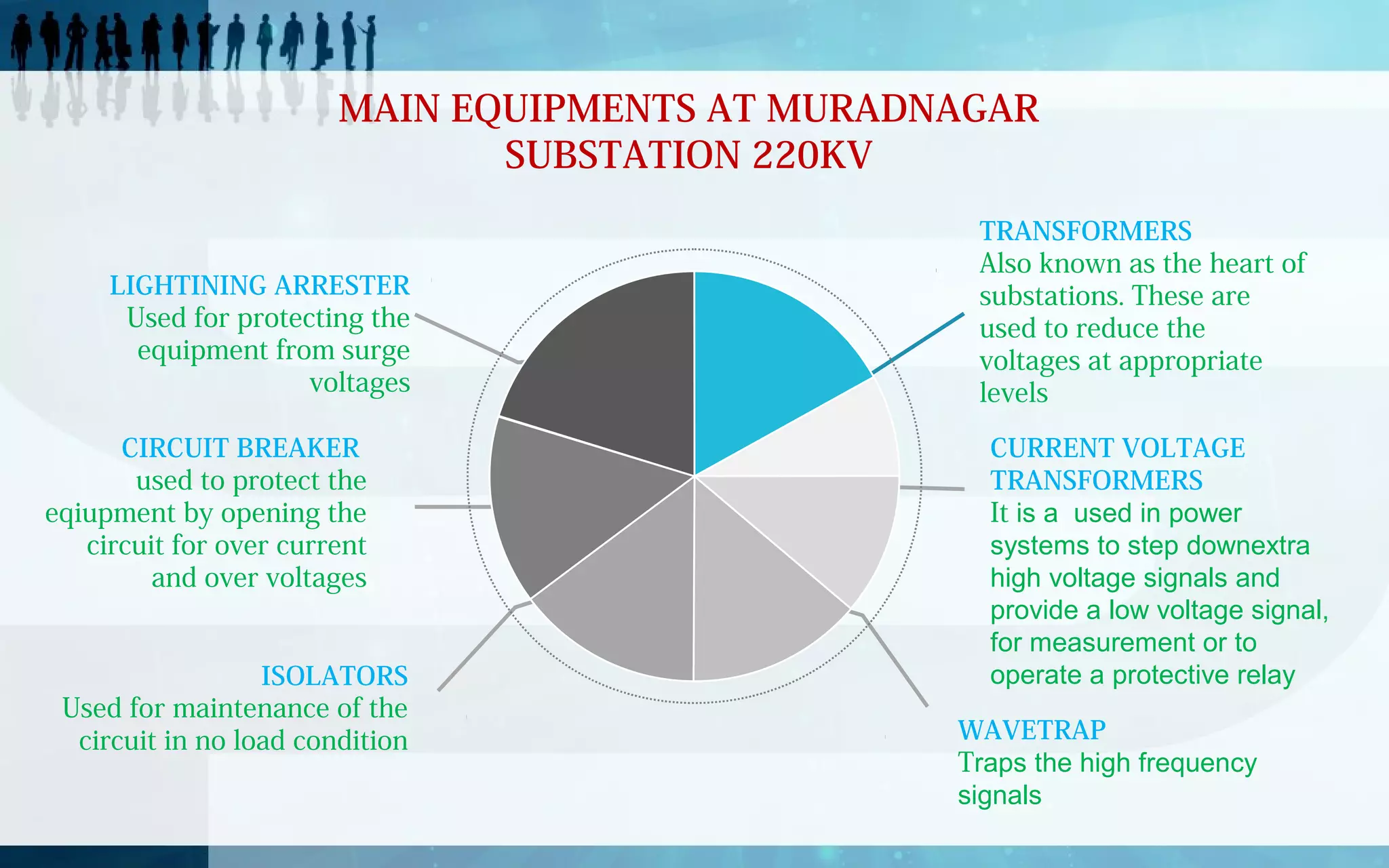
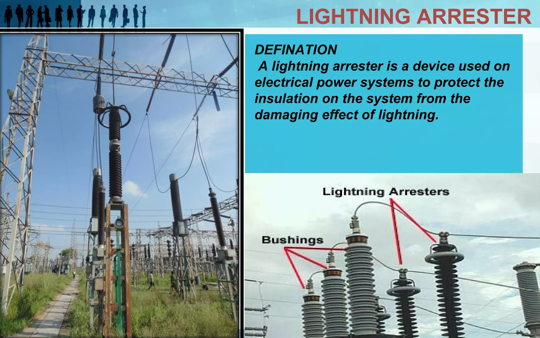


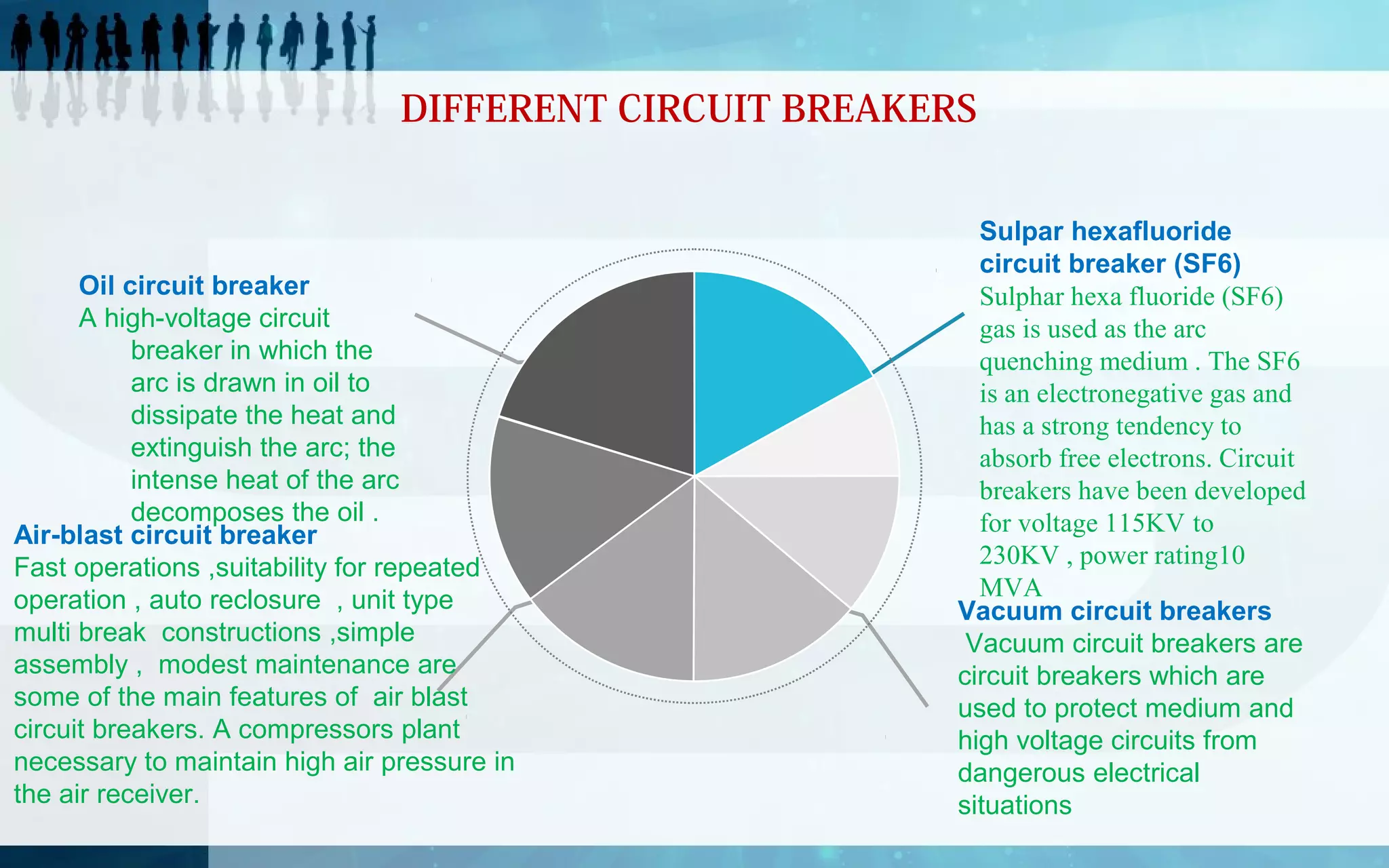
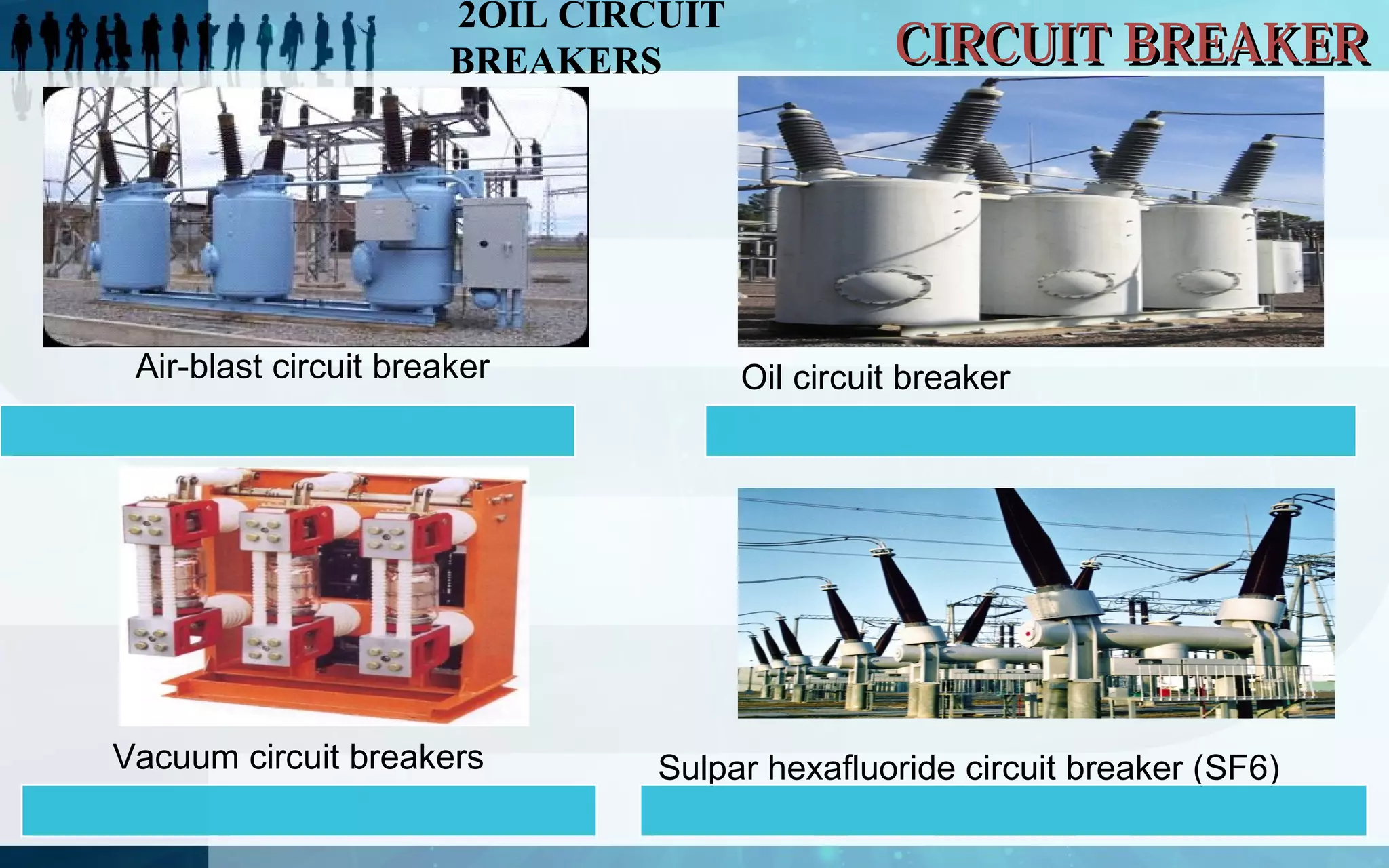
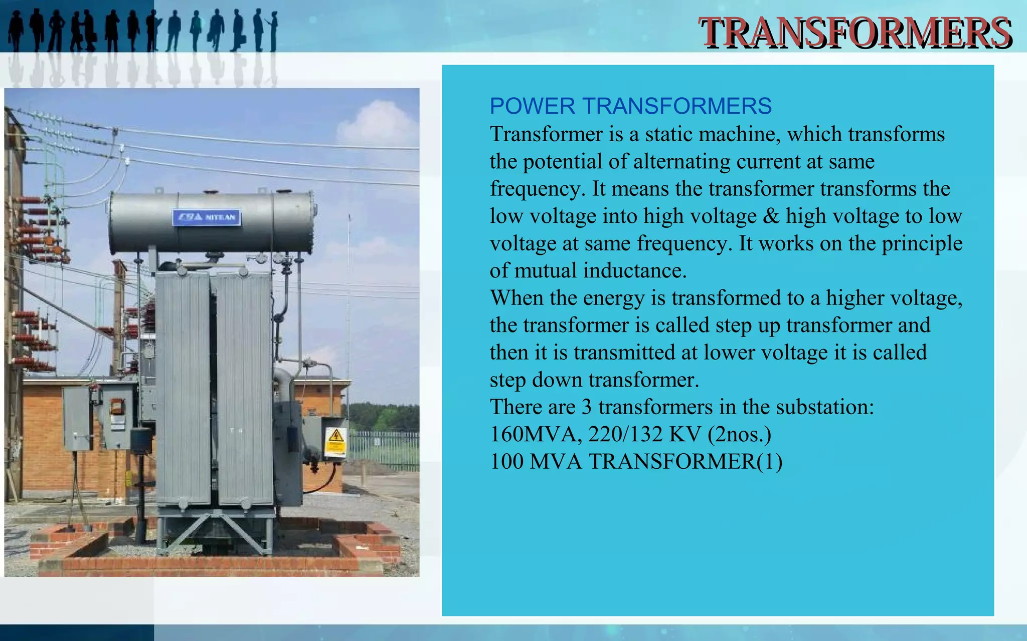
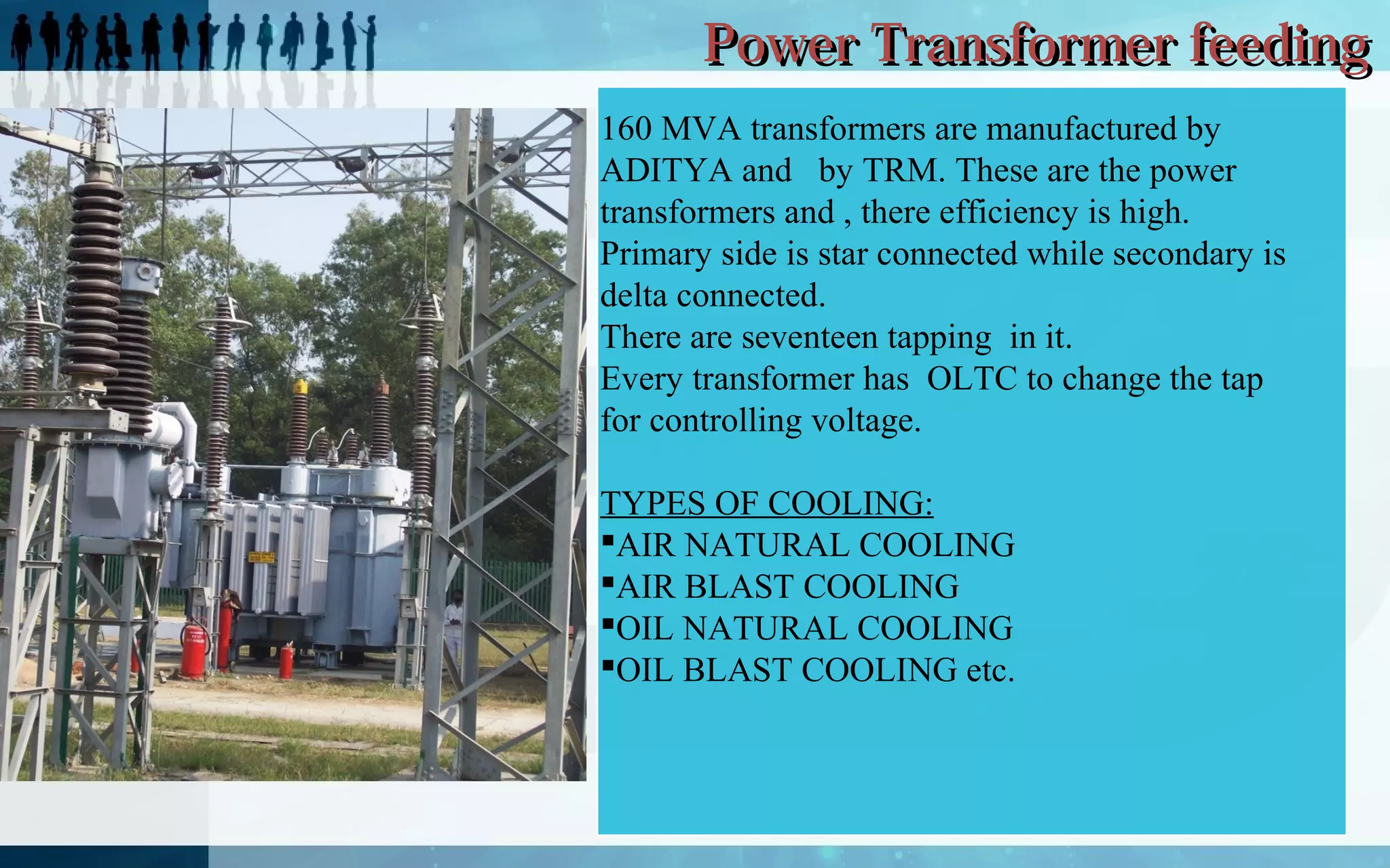


The 220kV power substation in Muradnagar has a capacity of 2*160MVA and 1*100MVA. It receives power from three 220kV transmission lines and two 400kV lines, which it steps down to lower voltages of 132kV, 66kV, 33kV and 11kV. The substation contains various equipment like circuit breakers, isolators, transformers, lightning arrestors, current and potential transformers, and wave traps to distribute, monitor and protect the flow of electricity. It utilizes equipment like oil and air-blast circuit breakers, vacuum and SF6 gas circuit breakers, and oil and air-cooled power transformers in its operations.


