Downloaded 240 times


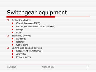


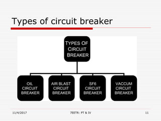

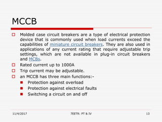


The document provides an overview of switchgear and its components, including protection, switching, and control devices essential for managing electrical circuits. Key components discussed include circuit breakers, miniature circuit breakers (MCBs), moulded case circuit breakers (MCCBs), relays, current transformers, bus bars, fuses, and switches. It emphasizes the importance of switchgear in ensuring the safe and efficient operation of electrical power systems.


