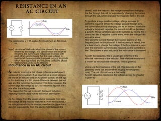
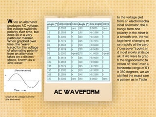
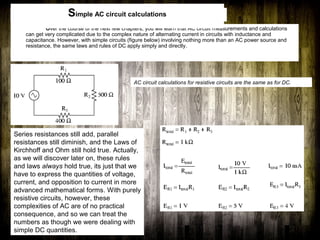
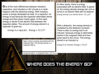
AC CIRCUIT
Content
•What is AC Circuit
•AC Transformers
•Resistance in an AC circuit
•Inductance in an AC circuit
•AC waveform
•Simple AC circuit calculations
•Where does the energy go?
What is alternating current (AC)?
Electric current that reverses direction
periodically, usually many times per
second. Electrical energy is
ordinarily generated by a public or
a private utility organization and
provided to a customer, whether
industrial or domestic, as
alternating current.
One complete period, with current flow
first in one direction and then in the
other, is called a cycle, and 60
cycles per second (60 hertz) is the
customary frequency of alternation
in the United States and in all of
North America. In Europe and in
many other parts of the world, 50
Hz is the standard frequency. On
aircraft a higher frequency, often
400 Hz, is used to make possible
lighter electrical machines.
•AC stands for “Alternating
Current,” meaning voltage or current
that changes polarity or direction,
respectively, over time.
•AC electromechanical generators,
known as alternators, are of simpler
construction than DC
electromechanical generators.
In General
In dept
What is alternating current (AC)?
One might wonder why anyone would
bother with such a thing as AC. It is true
that in some cases AC holds no
practical advantage over DC. In
applications where electricity is used to
dissipate energy in the form of heat, the
polarity or direction of current is
irrelevant, so long as there is enough
voltage and current to the load to
produce the desired heat (power
dissipation). However, with AC it is
possible to build electric generators,
motors and power distribution systems
that are far more efficient than DC, and
so we find AC used predominately
across the world in high power
applications.
To explain the details of why this is so, a bit
of background knowledge about AC is
necessary. If a machine is constructed
to rotate a magnetic field around a set of
stationary wire coils with the turning of a
shaft, AC voltage will be produced
across the wire coils as that shaft is
rotated, in accordance with Faraday's
Law of electromagnetic induction. This
is the basic operating principle of an AC
generator, also known as an alternator:
The fundamental significance of a transformer is its ability to step voltage
up or down from the powered coil to the unpowered coil. The AC
voltage induced in the unpowered (“secondary”) coil is equal to the
AC voltage across the powered (“primary”) coil multiplied by the
ratio of secondary coil turns to primary coil turns. If the secondary
coil is powering a load, the current through the secondary coil is
just the opposite: primary coil current multiplied by the ratio of
primary to secondary turns. This relationship has a very close
mechanical analogy, using torque and speed to represent voltage
and current, respectively
Speed multiplication gear train steps torque down and speed up. Step-
down transformer steps voltage down and current up.
If the winding ratio is reversed so that the primary coil has less turns than
the secondary coil, the transformer “steps up” the voltage from the
source level to a higher level at the load:
speed reduction gear train steps torque up and speed down. Step-up
transformer steps voltage up and current down.
AC Transformers
Transformers enable efficient long distance
high voltage transmission of electric energy.
Transformer technology has made long-range
electric power distribution practical. Without the
ability to efficiently step voltage up and down, it
would be cost-prohibitive to construct power sys
tems for anything but close-range (within a few
miles at most) use.
The transformer's ability to step AC
voltage up or down with ease gives AC an
advantage unmatched by DC in the realm
of power distribution in figure below.
When transmitting electrical power over
long distances, it is far more efficient to do
so with stepped-up voltages and stepped-
down currents (smaller-diameter wire with
less resistive power losses), then step the
voltage back down and the current back
up for industry, business, or consumer
use.
Resistance in an
ac ciRcuit
The relationship V = IR applies for resistors in an AC circuit,
so
In AC circuits we'll talk a lot about the phase of the current
relative to the voltage. In a circuit which only involves
resistors, the current and voltage are in phase with
each other, which means that the peak voltage is
reached at the same instant as peak current. In circuits
which have capacitors and inductors (coils) the phase
relationships will be quite different.
plates). With the inductor, the voltage comes from changing
the flux through the coil, or, equivalently, changing the current
through the coil, which changes the magnetic field in the coil.
To produce a large positive voltage, a large increase in
current is required. When the voltage passes through zero,
the current should stop changing just for an instant. When the
voltage is large and negative, the current should be decreasin
g quickly. These conditions can all be satisfied by having the c
urrent vary like a negative cosine wave, when the voltage follo
ws a sine wave.
How does the current through the inductor depend on the
frequency and the inductance? If the frequency is raised, ther
e is less time to change the voltage. If the time interval is redu
ced, the change in current is also reduced, so the current is lo
wer. The current is also reduced if the inductance is increased
.
As with the capacitor, this is usually put in terms of the
effective resistance of the inductor. This effective resistance i
s known as the inductive reactance. This is given by:
where L is the inductance of the coil (this depends on the
geometry of the coil and whether its got a ferromagnetic
core). The unit of inductance is the henry.
As with capacitive reactance, the voltage across the inductor
is given by:
Inductance in an AC circuit
An inductor is simply a coil of wire (often wrapped around
a piece of ferromagnet). If we now look at a circuit compos
ed only of an inductor and an AC power source, we will aga
in find that there is a 90° phase difference between the volt
age and the current in the inductor. This time, however, the
current lags the voltage by 90°, so it reaches its peak 1/4 c
ycle after the voltage peaks.
The reason for this has to do with the law of induction:
Applying Kirchoff's loop rule to the circuit above gives:
As the voltage from the power source increases from zero,
the voltage on the inductor matches it. With the capacitor, t
he voltage came from the charge stored on the capacitor pl
ates (or, equivalently, from the electric field between the
When an alternator
produces AC voltage,
the voltage switches
polarity over time, but
does so in a very
particular manner.
When graphed over
time, the “wave”
traced by this voltage
of alternating polarity
from an alternator
takes on a distinct
shape, known as a
sine wave:
In the voltage plot
from an electromecha
nical alternator, the c
hange from one
polarity to the other is
a smooth one, the vol
tage level changing m
ost rapidly at the zero
(“crossover”) point an
d most slowly at its pe
ak. If we were to grap
h the trigonometric fu
nction of “sine” over a
horizontal range of 0 t
o 360 degrees, we wo
uld find the exact sam
e pattern as in Table
AC waveform
Graph of AC voltage over time
(the sine wave).
Over the course of the next few chapters, you will learn that AC circuit measurements and calculations
can get very complicated due to the complex nature of alternating current in circuits with inductance and
capacitance. However, with simple circuits (figure below) involving nothing more than an AC power source and
resistance, the same laws and rules of DC apply simply and directly.
AC circuit calculations for resistive circuits are the same as for DC.
Series resistances still add, parallel
resistances still diminish, and the Laws of
Kirchhoff and Ohm still hold true. Actually,
as we will discover later on, these rules
and laws always hold true, its just that we
have to express the quantities of voltage,
current, and opposition to current in more
advanced mathematical forms. With purely
resistive circuits, however, these
complexities of AC are of no practical
consequence, and so we can treat the
numbers as though we were dealing with
simple DC quantities.
Simple AC circuit calculations
One of the main differences between resistors,
capacitors, and inductors in AC circuits is in what
happens with the electrical energy. With resistors,
power is simply dissipated as heat. In a capacitor, no
energy is lost because the capacitor alternately stores
charge and then gives it back again. In this case,
energy is stored in the electric field between the
capacitor plates. The amount of energy stored in a
capacitor is given by:
In other words, there is energy
associated with an electric field. In gener
al, the energy density (energy per unit vo
lume) in an electric field with no dielectri
c is:
With a dielectric, the energy density is
multiplied by the dielectric constant.
There is also no energy lost in an
inductor, because energy is alternately
stored in the magnetic field and then
given back to the circuit. The energy
stored in an inductor is:Again, there is energy associated with the
magnetic field. The energy density in a
magnetic field is:
Where does the energy go?
References
• http://physics.bu.edu/~duffy/PY106/ACcircui
ts.html
• http://www.micro.magnet.fsu.edu/electrom
ag/java/diode/index.html
• http://www.answers.com/topic/alternating-
current
• Harvey Lew (February 7, 2004):
Corrected typographical error: “circuit” sho
uld have been “circle”.
• Duane Damiano (February 25, 2003):
Pointed out magnetic polarity error in DC
generator illustration.
• Mark D. Zarella (April 28, 2002):
Suggestion for improving explanation of “a
verage” waveform amplitude.
• John Symonds (March 28, 2002):
Suggestion for improving explanation of
the unit “Hertz.”
• Jason Starck (June 2000): HTML
document formatting, which led to a much
better-looking second edition.

AC circuit

  • 1.
  • 2.
    Content •What is ACCircuit •AC Transformers •Resistance in an AC circuit •Inductance in an AC circuit •AC waveform •Simple AC circuit calculations •Where does the energy go?
  • 3.
    What is alternatingcurrent (AC)? Electric current that reverses direction periodically, usually many times per second. Electrical energy is ordinarily generated by a public or a private utility organization and provided to a customer, whether industrial or domestic, as alternating current. One complete period, with current flow first in one direction and then in the other, is called a cycle, and 60 cycles per second (60 hertz) is the customary frequency of alternation in the United States and in all of North America. In Europe and in many other parts of the world, 50 Hz is the standard frequency. On aircraft a higher frequency, often 400 Hz, is used to make possible lighter electrical machines. •AC stands for “Alternating Current,” meaning voltage or current that changes polarity or direction, respectively, over time. •AC electromechanical generators, known as alternators, are of simpler construction than DC electromechanical generators. In General In dept
  • 4.
    What is alternatingcurrent (AC)? One might wonder why anyone would bother with such a thing as AC. It is true that in some cases AC holds no practical advantage over DC. In applications where electricity is used to dissipate energy in the form of heat, the polarity or direction of current is irrelevant, so long as there is enough voltage and current to the load to produce the desired heat (power dissipation). However, with AC it is possible to build electric generators, motors and power distribution systems that are far more efficient than DC, and so we find AC used predominately across the world in high power applications. To explain the details of why this is so, a bit of background knowledge about AC is necessary. If a machine is constructed to rotate a magnetic field around a set of stationary wire coils with the turning of a shaft, AC voltage will be produced across the wire coils as that shaft is rotated, in accordance with Faraday's Law of electromagnetic induction. This is the basic operating principle of an AC generator, also known as an alternator:
  • 5.
    The fundamental significanceof a transformer is its ability to step voltage up or down from the powered coil to the unpowered coil. The AC voltage induced in the unpowered (“secondary”) coil is equal to the AC voltage across the powered (“primary”) coil multiplied by the ratio of secondary coil turns to primary coil turns. If the secondary coil is powering a load, the current through the secondary coil is just the opposite: primary coil current multiplied by the ratio of primary to secondary turns. This relationship has a very close mechanical analogy, using torque and speed to represent voltage and current, respectively Speed multiplication gear train steps torque down and speed up. Step- down transformer steps voltage down and current up. If the winding ratio is reversed so that the primary coil has less turns than the secondary coil, the transformer “steps up” the voltage from the source level to a higher level at the load: speed reduction gear train steps torque up and speed down. Step-up transformer steps voltage up and current down. AC Transformers Transformers enable efficient long distance high voltage transmission of electric energy. Transformer technology has made long-range electric power distribution practical. Without the ability to efficiently step voltage up and down, it would be cost-prohibitive to construct power sys tems for anything but close-range (within a few miles at most) use. The transformer's ability to step AC voltage up or down with ease gives AC an advantage unmatched by DC in the realm of power distribution in figure below. When transmitting electrical power over long distances, it is far more efficient to do so with stepped-up voltages and stepped- down currents (smaller-diameter wire with less resistive power losses), then step the voltage back down and the current back up for industry, business, or consumer use.
  • 6.
    Resistance in an acciRcuit The relationship V = IR applies for resistors in an AC circuit, so In AC circuits we'll talk a lot about the phase of the current relative to the voltage. In a circuit which only involves resistors, the current and voltage are in phase with each other, which means that the peak voltage is reached at the same instant as peak current. In circuits which have capacitors and inductors (coils) the phase relationships will be quite different. plates). With the inductor, the voltage comes from changing the flux through the coil, or, equivalently, changing the current through the coil, which changes the magnetic field in the coil. To produce a large positive voltage, a large increase in current is required. When the voltage passes through zero, the current should stop changing just for an instant. When the voltage is large and negative, the current should be decreasin g quickly. These conditions can all be satisfied by having the c urrent vary like a negative cosine wave, when the voltage follo ws a sine wave. How does the current through the inductor depend on the frequency and the inductance? If the frequency is raised, ther e is less time to change the voltage. If the time interval is redu ced, the change in current is also reduced, so the current is lo wer. The current is also reduced if the inductance is increased . As with the capacitor, this is usually put in terms of the effective resistance of the inductor. This effective resistance i s known as the inductive reactance. This is given by: where L is the inductance of the coil (this depends on the geometry of the coil and whether its got a ferromagnetic core). The unit of inductance is the henry. As with capacitive reactance, the voltage across the inductor is given by: Inductance in an AC circuit An inductor is simply a coil of wire (often wrapped around a piece of ferromagnet). If we now look at a circuit compos ed only of an inductor and an AC power source, we will aga in find that there is a 90° phase difference between the volt age and the current in the inductor. This time, however, the current lags the voltage by 90°, so it reaches its peak 1/4 c ycle after the voltage peaks. The reason for this has to do with the law of induction: Applying Kirchoff's loop rule to the circuit above gives: As the voltage from the power source increases from zero, the voltage on the inductor matches it. With the capacitor, t he voltage came from the charge stored on the capacitor pl ates (or, equivalently, from the electric field between the
  • 7.
    When an alternator producesAC voltage, the voltage switches polarity over time, but does so in a very particular manner. When graphed over time, the “wave” traced by this voltage of alternating polarity from an alternator takes on a distinct shape, known as a sine wave: In the voltage plot from an electromecha nical alternator, the c hange from one polarity to the other is a smooth one, the vol tage level changing m ost rapidly at the zero (“crossover”) point an d most slowly at its pe ak. If we were to grap h the trigonometric fu nction of “sine” over a horizontal range of 0 t o 360 degrees, we wo uld find the exact sam e pattern as in Table AC waveform Graph of AC voltage over time (the sine wave).
  • 8.
    Over the courseof the next few chapters, you will learn that AC circuit measurements and calculations can get very complicated due to the complex nature of alternating current in circuits with inductance and capacitance. However, with simple circuits (figure below) involving nothing more than an AC power source and resistance, the same laws and rules of DC apply simply and directly. AC circuit calculations for resistive circuits are the same as for DC. Series resistances still add, parallel resistances still diminish, and the Laws of Kirchhoff and Ohm still hold true. Actually, as we will discover later on, these rules and laws always hold true, its just that we have to express the quantities of voltage, current, and opposition to current in more advanced mathematical forms. With purely resistive circuits, however, these complexities of AC are of no practical consequence, and so we can treat the numbers as though we were dealing with simple DC quantities. Simple AC circuit calculations
  • 9.
    One of themain differences between resistors, capacitors, and inductors in AC circuits is in what happens with the electrical energy. With resistors, power is simply dissipated as heat. In a capacitor, no energy is lost because the capacitor alternately stores charge and then gives it back again. In this case, energy is stored in the electric field between the capacitor plates. The amount of energy stored in a capacitor is given by: In other words, there is energy associated with an electric field. In gener al, the energy density (energy per unit vo lume) in an electric field with no dielectri c is: With a dielectric, the energy density is multiplied by the dielectric constant. There is also no energy lost in an inductor, because energy is alternately stored in the magnetic field and then given back to the circuit. The energy stored in an inductor is:Again, there is energy associated with the magnetic field. The energy density in a magnetic field is: Where does the energy go?
  • 10.
    References • http://physics.bu.edu/~duffy/PY106/ACcircui ts.html • http://www.micro.magnet.fsu.edu/electrom ag/java/diode/index.html •http://www.answers.com/topic/alternating- current • Harvey Lew (February 7, 2004): Corrected typographical error: “circuit” sho uld have been “circle”. • Duane Damiano (February 25, 2003): Pointed out magnetic polarity error in DC generator illustration. • Mark D. Zarella (April 28, 2002): Suggestion for improving explanation of “a verage” waveform amplitude. • John Symonds (March 28, 2002): Suggestion for improving explanation of the unit “Hertz.” • Jason Starck (June 2000): HTML document formatting, which led to a much better-looking second edition.