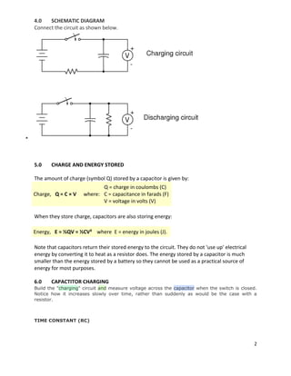
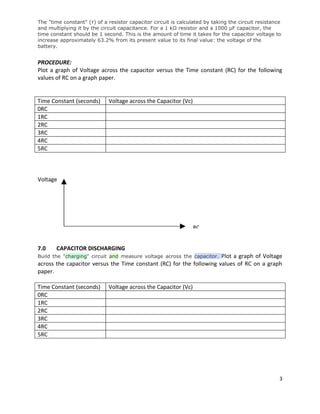
SlideShare a Scribd company logo
1 of 3
THE KENYA POLYTECHNIC
                                        UNIVERSITY COLLEGE

                   DEPARTMENT OF ELECTRICAL AND ELECTRONIC ENGINEERING


                    CERTIFICATE IN COMPUTER SERVICING AND MAINTENANCE


                  EXPERIMENT: CHARGING AND DISCHARGING OF A CAPACITOR


1.0     Capacitance
Capacitance (symbol C) is a measure of a capacitor's ability to store charge. A large capacitance
means that more charge can be stored. Capacitance is measured in farads, symbol F. However
1F is very large, so prefixes (multipliers) are used to show the smaller values:

         µ (micro) means 10-6 (millionth), so 1000000µF = 1F
         n (nano) means 10-9 (thousand-millionth), so 1000nF = 1µF
         p (pico) means 10-12 (million-millionth), so 1000pF = 1n


2.0       PARTS AND MATERIALS
         6 volt battery/ DC Power Supply
         Two large electrolytic capacitors, 1000 µF minimum
         Two 47KΩ resistors or any other value close to this.
         One toggle switch, SPST ("Single-Pole, Single-Throw")
         Voltmeter
         Stop Watch

Note: Be warned that most large capacitors are of the "electrolytic" type, and they are polarity
sensitive! One terminal of each capacitor should be marked with a definite polarity sign. Usually
capacitors of the size specified have a negative (-) marking or series of negative markings
pointing toward the negative terminal. Very large capacitors are often polarity-labeled by a
positive (+) marking next to one terminal. Failure to heed proper polarity will almost surely
result in capacitor failure, even with a source voltage as low as 6 volts. When electrolytic
capacitors fail, they typically explode, spewing caustic chemicals and emitting foul odors.
Please, try to avoid this!

3.0       LEARNING OBJECTIVES
         Capacitor charging action
         Capacitor discharging action
         Time constant calculation
         Series and parallel capacitance


                                                                                                1
4.0   SCHEMATIC DIAGRAM
    Connect the circuit as shown below.





    5.0    CHARGE AND ENERGY STORED

    The amount of charge (symbol Q) stored by a capacitor is given by:
                                 Q = charge in coulombs (C)
    Charge, Q = C × V     where: C = capacitance in farads (F)
                                 V = voltage in volts (V)

    When they store charge, capacitors are also storing energy:

    Energy, E = ½QV = ½CV² where E = energy in joules (J).

    Note that capacitors return their stored energy to the circuit. They do not 'use up' electrical
    energy by converting it to heat as a resistor does. The energy stored by a capacitor is much
    smaller than the energy stored by a battery so they cannot be used as a practical source of
    energy for most purposes.

    6.0    CAPACTITOR CHARGING
    Build the "charging" circuit and measure voltage across the capacitor when the switch is closed.
    Notice how it increases slowly over time, rather than suddenly as would be the case with a
    resistor.


    TIME CONSTANT (RC)


                                                                                                      2
The "time constant" (τ) of a resistor capacitor circuit is calculated by taking the circuit resistance
and multiplying it by the circuit capacitance. For a 1 kΩ resistor and a 1000 µF capacitor, the
time constant should be 1 second. This is the amount of time it takes for the capacitor voltage to
increase approximately 63.2% from its present value to its final value: the voltage of the
battery.


PROCEDURE:
Plot a graph of Voltage across the capacitor versus the Time constant (RC) for the following
values of RC on a graph paper.


Time Constant (seconds)      Voltage across the Capacitor (Vc)
0RC
1RC
2RC
3RC
4RC
5RC


Voltage


                                                                 RC


7.0    CAPACITOR DISCHARGING
Build the "charging" circuit and measure voltage across the capacitor.Plot a graph of Voltage
across the capacitor versus the Time constant (RC) for the following values of RC on a graph
paper.

Time Constant (seconds)      Voltage across the Capacitor (Vc)
0RC
1RC
2RC
3RC
4RC
5RC


                                                                                                     3

More Related Content

What's hot

PSCAD Final Report
PSCAD Final ReportPSCAD Final Report
PSCAD Final Report
Jeff Ge
 
Power system-protection-presentation-dated-03-10-2013-integrated-protection-c...
Power system-protection-presentation-dated-03-10-2013-integrated-protection-c...Power system-protection-presentation-dated-03-10-2013-integrated-protection-c...
Power system-protection-presentation-dated-03-10-2013-integrated-protection-c...
jbpatel7290
 

What's hot (20)

PSCAD Final Report
PSCAD Final ReportPSCAD Final Report
PSCAD Final Report
 
Testing of Transformer (AREVA)
Testing of Transformer (AREVA)Testing of Transformer (AREVA)
Testing of Transformer (AREVA)
 
COMPENSATION OF HARMONIC CURRENTS UTILIZING AHC( ACTIVE HARMONIC COMPENSATOR)
COMPENSATION OF HARMONIC CURRENTS UTILIZING AHC( ACTIVE HARMONIC COMPENSATOR)COMPENSATION OF HARMONIC CURRENTS UTILIZING AHC( ACTIVE HARMONIC COMPENSATOR)
COMPENSATION OF HARMONIC CURRENTS UTILIZING AHC( ACTIVE HARMONIC COMPENSATOR)
 
Ohm's Law
Ohm's LawOhm's Law
Ohm's Law
 
Armaturereaction&commutation
Armaturereaction&commutationArmaturereaction&commutation
Armaturereaction&commutation
 
Symmetrical components
Symmetrical componentsSymmetrical components
Symmetrical components
 
Basic protection and relaying
Basic protection and relayingBasic protection and relaying
Basic protection and relaying
 
Report on Thevenin's theorem
Report on Thevenin's theoremReport on Thevenin's theorem
Report on Thevenin's theorem
 
Overcurrent coordination
Overcurrent coordinationOvercurrent coordination
Overcurrent coordination
 
Lightning arresters
Lightning arrestersLightning arresters
Lightning arresters
 
Symmetrical component
Symmetrical componentSymmetrical component
Symmetrical component
 
Flashover Tests
Flashover TestsFlashover Tests
Flashover Tests
 
relationship between line and phase values of voltage and current for the sta...
relationship between line and phase values of voltage and current for the sta...relationship between line and phase values of voltage and current for the sta...
relationship between line and phase values of voltage and current for the sta...
 
Dynamic Voltage Regulator
Dynamic Voltage RegulatorDynamic Voltage Regulator
Dynamic Voltage Regulator
 
FREQUENCY STABILITY
FREQUENCY STABILITYFREQUENCY STABILITY
FREQUENCY STABILITY
 
Power system-protection-presentation-dated-03-10-2013-integrated-protection-c...
Power system-protection-presentation-dated-03-10-2013-integrated-protection-c...Power system-protection-presentation-dated-03-10-2013-integrated-protection-c...
Power system-protection-presentation-dated-03-10-2013-integrated-protection-c...
 
Improvement of power quality using series active power filter
Improvement of power quality using series active power filterImprovement of power quality using series active power filter
Improvement of power quality using series active power filter
 
Generator Protection Relay Setting Calculations
Generator Protection Relay Setting CalculationsGenerator Protection Relay Setting Calculations
Generator Protection Relay Setting Calculations
 
ppt of Three phase fault analysis with auto reset for temporary fault and tri...
ppt of Three phase fault analysis with auto reset for temporary fault and tri...ppt of Three phase fault analysis with auto reset for temporary fault and tri...
ppt of Three phase fault analysis with auto reset for temporary fault and tri...
 
Power Flow Analysis using Power World Simulator
Power Flow Analysis using Power World SimulatorPower Flow Analysis using Power World Simulator
Power Flow Analysis using Power World Simulator
 

Viewers also liked

Inductorless DC-AC Cascaded H-bridge Multilevel Boost Inverter for Electric/...
Inductorless DC-AC Cascaded H-bridge MultilevelBoost Inverter for Electric/...Inductorless DC-AC Cascaded H-bridge MultilevelBoost Inverter for Electric/...
Inductorless DC-AC Cascaded H-bridge Multilevel Boost Inverter for Electric/...
mkanth
 
Induction Synchronous Motor
Induction Synchronous MotorInduction Synchronous Motor
Induction Synchronous Motor
Shahzad Khalil
 
Circuitos serie-y-paralelo-ejercicios
Circuitos serie-y-paralelo-ejerciciosCircuitos serie-y-paralelo-ejercicios
Circuitos serie-y-paralelo-ejercicios
Cristian Garcia
 

Viewers also liked (16)

Initial and final condition for circuit
Initial and final condition for circuitInitial and final condition for circuit
Initial and final condition for circuit
 
Electricity
ElectricityElectricity
Electricity
 
The rc circuit
The rc circuitThe rc circuit
The rc circuit
 
Diode Applications Experiment 5
Diode Applications Experiment 5Diode Applications Experiment 5
Diode Applications Experiment 5
 
Understanding Split-phase Induction Motors
Understanding Split-phase Induction MotorsUnderstanding Split-phase Induction Motors
Understanding Split-phase Induction Motors
 
Type of Single phase induction Motor
Type of Single phase induction MotorType of Single phase induction Motor
Type of Single phase induction Motor
 
Reactive power compensation
Reactive power compensationReactive power compensation
Reactive power compensation
 
SERIES RESISTOR-CAPASITOR CIRCUIT experiment 7
SERIES RESISTOR-CAPASITOR CIRCUIT experiment 7SERIES RESISTOR-CAPASITOR CIRCUIT experiment 7
SERIES RESISTOR-CAPASITOR CIRCUIT experiment 7
 
Inductorless DC-AC Cascaded H-bridge Multilevel Boost Inverter for Electric/...
Inductorless DC-AC Cascaded H-bridge MultilevelBoost Inverter for Electric/...Inductorless DC-AC Cascaded H-bridge MultilevelBoost Inverter for Electric/...
Inductorless DC-AC Cascaded H-bridge Multilevel Boost Inverter for Electric/...
 
Electrical and electronics Lab Manual
Electrical and electronics Lab ManualElectrical and electronics Lab Manual
Electrical and electronics Lab Manual
 
Types of charging process
Types of charging processTypes of charging process
Types of charging process
 
automatic power factor controller
automatic power factor controllerautomatic power factor controller
automatic power factor controller
 
Capacitor motor
Capacitor motorCapacitor motor
Capacitor motor
 
Induction Synchronous Motor
Induction Synchronous MotorInduction Synchronous Motor
Induction Synchronous Motor
 
Semiconductor
SemiconductorSemiconductor
Semiconductor
 
Circuitos serie-y-paralelo-ejercicios
Circuitos serie-y-paralelo-ejerciciosCircuitos serie-y-paralelo-ejercicios
Circuitos serie-y-paralelo-ejercicios
 

Similar to Capacitor experiment

Loren k. schwappach ee331 - lab 3
Loren k. schwappach   ee331 - lab 3Loren k. schwappach   ee331 - lab 3
Loren k. schwappach ee331 - lab 3
Loren Schwappach
 
Sheet1resistance of resistorTime Constant = 5.3s10v from power sup.docx
Sheet1resistance of resistorTime Constant = 5.3s10v from power sup.docxSheet1resistance of resistorTime Constant = 5.3s10v from power sup.docx
Sheet1resistance of resistorTime Constant = 5.3s10v from power sup.docx
maoanderton
 
Elect principles -_capacitance
Elect principles -_capacitanceElect principles -_capacitance
Elect principles -_capacitance
sdacey
 

Similar to Capacitor experiment (20)

Loren k. schwappach ee331 - lab 3
Loren k. schwappach   ee331 - lab 3Loren k. schwappach   ee331 - lab 3
Loren k. schwappach ee331 - lab 3
 
Capacitors
CapacitorsCapacitors
Capacitors
 
Capacitor
CapacitorCapacitor
Capacitor
 
Transformador excercises para compartir
Transformador excercises para compartirTransformador excercises para compartir
Transformador excercises para compartir
 
AC in RC Circuits
AC in RC CircuitsAC in RC Circuits
AC in RC Circuits
 
FFFF.ppt
FFFF.pptFFFF.ppt
FFFF.ppt
 
Ch 17 student_201516
Ch 17 student_201516Ch 17 student_201516
Ch 17 student_201516
 
Lesson 2 Capacitors
Lesson 2  CapacitorsLesson 2  Capacitors
Lesson 2 Capacitors
 
cursoos.ppt
cursoos.pptcursoos.ppt
cursoos.ppt
 
Capacitors
CapacitorsCapacitors
Capacitors
 
Capacitors.ppt
Capacitors.pptCapacitors.ppt
Capacitors.ppt
 
ggggg.ppt
ggggg.pptggggg.ppt
ggggg.ppt
 
Sheet1resistance of resistorTime Constant = 5.3s10v from power sup.docx
Sheet1resistance of resistorTime Constant = 5.3s10v from power sup.docxSheet1resistance of resistorTime Constant = 5.3s10v from power sup.docx
Sheet1resistance of resistorTime Constant = 5.3s10v from power sup.docx
 
Capacitors.ppt
Capacitors.pptCapacitors.ppt
Capacitors.ppt
 
Capacitor aka condenser
Capacitor aka condenserCapacitor aka condenser
Capacitor aka condenser
 
RLC.ppt
RLC.pptRLC.ppt
RLC.ppt
 
Charging C
Charging  CCharging  C
Charging C
 
17-18_1.27_u4_physics_eng.pdf
17-18_1.27_u4_physics_eng.pdf17-18_1.27_u4_physics_eng.pdf
17-18_1.27_u4_physics_eng.pdf
 
Elect principles -_capacitance
Elect principles -_capacitanceElect principles -_capacitance
Elect principles -_capacitance
 
Wk 10 p1 8-18.1-18.2_capacitance
Wk 10 p1 8-18.1-18.2_capacitanceWk 10 p1 8-18.1-18.2_capacitance
Wk 10 p1 8-18.1-18.2_capacitance
 

Capacitor experiment

  • 1. THE KENYA POLYTECHNIC UNIVERSITY COLLEGE DEPARTMENT OF ELECTRICAL AND ELECTRONIC ENGINEERING CERTIFICATE IN COMPUTER SERVICING AND MAINTENANCE EXPERIMENT: CHARGING AND DISCHARGING OF A CAPACITOR 1.0 Capacitance Capacitance (symbol C) is a measure of a capacitor's ability to store charge. A large capacitance means that more charge can be stored. Capacitance is measured in farads, symbol F. However 1F is very large, so prefixes (multipliers) are used to show the smaller values:  µ (micro) means 10-6 (millionth), so 1000000µF = 1F  n (nano) means 10-9 (thousand-millionth), so 1000nF = 1µF  p (pico) means 10-12 (million-millionth), so 1000pF = 1n 2.0 PARTS AND MATERIALS  6 volt battery/ DC Power Supply  Two large electrolytic capacitors, 1000 µF minimum  Two 47KΩ resistors or any other value close to this.  One toggle switch, SPST ("Single-Pole, Single-Throw")  Voltmeter  Stop Watch Note: Be warned that most large capacitors are of the "electrolytic" type, and they are polarity sensitive! One terminal of each capacitor should be marked with a definite polarity sign. Usually capacitors of the size specified have a negative (-) marking or series of negative markings pointing toward the negative terminal. Very large capacitors are often polarity-labeled by a positive (+) marking next to one terminal. Failure to heed proper polarity will almost surely result in capacitor failure, even with a source voltage as low as 6 volts. When electrolytic capacitors fail, they typically explode, spewing caustic chemicals and emitting foul odors. Please, try to avoid this! 3.0 LEARNING OBJECTIVES  Capacitor charging action  Capacitor discharging action  Time constant calculation  Series and parallel capacitance 1
  • 2. 4.0 SCHEMATIC DIAGRAM Connect the circuit as shown below.  5.0 CHARGE AND ENERGY STORED The amount of charge (symbol Q) stored by a capacitor is given by: Q = charge in coulombs (C) Charge, Q = C × V where: C = capacitance in farads (F) V = voltage in volts (V) When they store charge, capacitors are also storing energy: Energy, E = ½QV = ½CV² where E = energy in joules (J). Note that capacitors return their stored energy to the circuit. They do not 'use up' electrical energy by converting it to heat as a resistor does. The energy stored by a capacitor is much smaller than the energy stored by a battery so they cannot be used as a practical source of energy for most purposes. 6.0 CAPACTITOR CHARGING Build the "charging" circuit and measure voltage across the capacitor when the switch is closed. Notice how it increases slowly over time, rather than suddenly as would be the case with a resistor. TIME CONSTANT (RC) 2
  • 3. The "time constant" (τ) of a resistor capacitor circuit is calculated by taking the circuit resistance and multiplying it by the circuit capacitance. For a 1 kΩ resistor and a 1000 µF capacitor, the time constant should be 1 second. This is the amount of time it takes for the capacitor voltage to increase approximately 63.2% from its present value to its final value: the voltage of the battery. PROCEDURE: Plot a graph of Voltage across the capacitor versus the Time constant (RC) for the following values of RC on a graph paper. Time Constant (seconds) Voltage across the Capacitor (Vc) 0RC 1RC 2RC 3RC 4RC 5RC Voltage RC 7.0 CAPACITOR DISCHARGING Build the "charging" circuit and measure voltage across the capacitor.Plot a graph of Voltage across the capacitor versus the Time constant (RC) for the following values of RC on a graph paper. Time Constant (seconds) Voltage across the Capacitor (Vc) 0RC 1RC 2RC 3RC 4RC 5RC 3