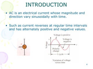
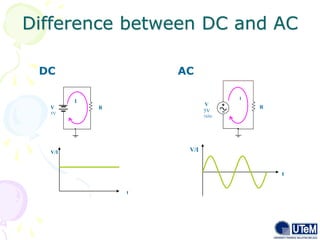
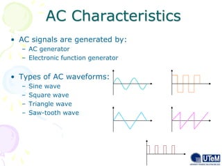
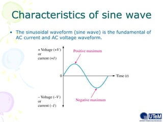
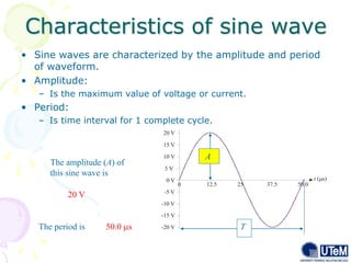
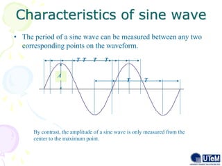
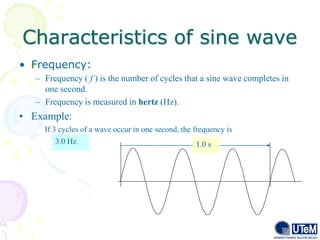
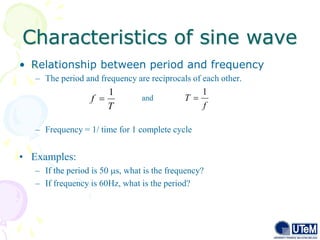
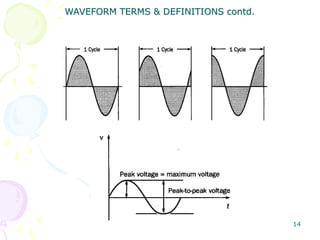
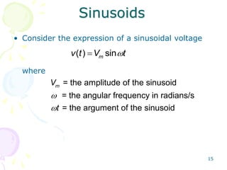
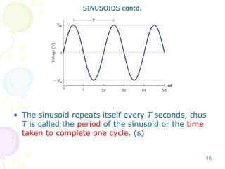
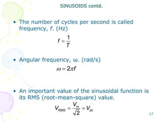
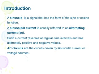
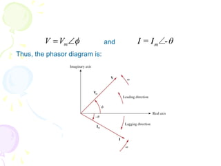
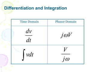
BEKG 1123
PRINCIPLES OF ELECTRIC &
ELECTRONICS
2
CHAPTER 3:
AC Sources
and
AC Characteristic
AC Source
Learning Outcome
• In this part, we will cover on:
4.1 Waveform type
4.2 AC characteristic
3
4
• AC is an electrical current whose magnitude and
direction vary sinusoidally with time.
• Such as current reverses at regular time intervals
and has alternately positive and negative values.
INTRODUCTION
5
• The circuits analysis is considering the time-
varying voltage source or current source.
• Circuits driven by sinusoidal current or voltage
sources are called ac circuits.
• A sinusoid can be express in either sine or
cosine form.
INTRODUCTION..cont
Difference between DC and AC
DC AC
6
V
5V
1kHz
R
I
V/I
t
V
5V
I
R
V/I
t
AC Characteristics
7
• AC signals are generated by:
– AC generator
– Electronic function generator
• Types of AC waveforms:
– Sine wave
– Square wave
– Triangle wave
– Saw-tooth wave
Characteristics of sine wave
8
• The sinusoidal waveform (sine wave) is the fundamental of
AC current and AC voltage waveform.
Characteristics of sine wave
9
• Sine waves are characterized by the amplitude and period
of waveform.
• Amplitude:
– Is the maximum value of voltage or current.
• Period:
– Is time interval for 1 complete cycle.
0 V
10 V
-10 V
15 V
-15 V
-20 V
t ( s)

0 25 37.5 50.0
20 V
The amplitude (A) of
this sine wave is
20 V
The period is 50.0 s
A
T
Characteristics of sine wave
10
• The period of a sine wave can be measured between any two
corresponding points on the waveform.
T T T T
T T
A
By contrast, the amplitude of a sine wave is only measured from the
center to the maximum point.
Characteristics of sine wave
11
• Frequency:
– Frequency ( f ) is the number of cycles that a sine wave completes in
one second.
– Frequency is measured in hertz (Hz).
• Example:
3.0 Hz
If 3 cycles of a wave occur in one second, the frequency is
1.0 s
Characteristics of sine wave
12
• Relationship between period and frequency
– The period and frequency are reciprocals of each other.
– Frequency = 1/ time for 1 complete cycle
• Examples:
– If the period is 50 s, what is the frequency?
– If frequency is 60Hz, what is the period?
and
f
T
1

T
f
1

13
Waveform Terms &
Definitions
Definitions:
Period – the time taken to complete a cycle, T (s)
Peak value – the maximum instantaneous value measured from its zero value, Vp @
Vm (V)
Peak-to-peak value – the maximum variation between the maximum positive
instantaneous value and the maximum negative value, Vp-p (V)
Instantaneous voltage / current - has a value that corresponds to a specific time t.
Every waveform has an infinity number of instantaneous values. Such a waveform
is described as the parameter as a function of time. In the case of a voltage it will
be written as v(t).
Cycle – the portion of a waveform contained in one period of time. For a sine wave,
it is the complete event starting with a rise from zero energy to a maximum
amplitude, its return to zero, the rise to a maximum in the opposite direction, and
then its return to zero.
14
WAVEFORM TERMS & DEFINITIONS contd.
15
Sinusoids
• Consider the expression of a sinusoidal voltage
where


( ) sin
m
v t V t


= the amplitude of the sinusoid
= the angular frequency in radians/s
= the argument of the sinusoid
m
V
t
16
• The sinusoid repeats itself every T seconds, thus
T is called the period of the sinusoid or the time
taken to complete one cycle. (s)
SINUSOIDS contd.
17
• The number of cycles per second is called
frequency, f. (Hz)
• Angular frequency, ω. (rad/s)
• An important value of the sinusoidal function is
its RMS (root-mean-square) value.
SINUSOIDS contd.
1
f
T

2 f
 

 
2
m
RMS dc
V
V V
18
• Note: Radian measure
– ω is usually expressed in radian/s
– 2 radians = 360
– to convert from degrees to radians, multiply by /180.
– to convert from radians to degrees, multiply by 180/.
• From the general expression of the sinusoidal
voltage, we can find the value of voltage at any
given instant of time.
SINUSOIDS contd.
19
• If the waveform does not pass through zero at
t=0, it has a phase shift.
• For a waveform shifted left,
• For waveform shifted right,
where
 
 
 
( ) sin
m
v t V t
 = phase angle of the sinusoid function
SINUSOIDS contd.
 
 
 
( ) sin
m
v t V t
20
SINUSOIDS contd.
21
Example:
1. Find the amplitude, phase, period and
frequency of the sinusoid
Solution:
Amplitude, Vm = 12V
Phase, = 10˚
Angular frequency, ω = 50rad/s
thus the period, T =
The frequency, f =
SINUSOIDS contd.

2 2
50
0.1257s
 

 
7.958
1
z
T
H

 
  
( ) 12sin 50 10
v t t
22
2. A sinusoidal voltage is given by the expression
V = 300 cos (120t + 30).
a) What is the frequency in Hz?
b) What is the period of the voltage in miliseconds?
c) What is the magnitude of V at t = 2.778ms?
d) What is the RMS value of V?
Solution:
a) Given ω = 120 = 2f, thus f = 60Hz
b) T = 1/f = 16.67ms
c) V = V = 300 cos (120x2.778m + 30)
= 300 cos (60 + 30) = 0V
d) Vrms = 300/√2 = 212.13V
SINUSOIDS contd.
23
• Consider the following:
SINUSOIDS contd.
1( ) sin
m
v t V t

  
2( ) sin
m
v t V t
 
 
24
• The v2 is occurred first in time.
• Thus it can be said that v2 leads v1 by or v1
lags v2 by .
• If ≠ 0 we can say v1 and v2 are out of phase.
• If = 0 we can say v1 and v2 are in phase.
• v1 and v2 can be compared in this manner
because they operate at the same frequency (do
not need to have the same amplitude).
SINUSOIDS contd.




25
• Transformation between cosine and sine form
Converting from negative to positive magnitude
where
SINUSOIDS contd.
sin cos( 90 )
cos sin( 90 )
A A
A A
  
  
sin sin( 180 )
cos cos( 180 )
A A
A A
   
   
A t
 
 
26
Example:
1. For the following sinusoidal voltage, find the
value v at t = 0s and t = 0.5s.
v = 6 cos (100t + 60˚)
Solution:
Note: both ωt and must be in same unit before adding them up.
SINUSOIDS contd.
at t = 0.5s
v = 6 cos (50 rad +60˚)
= 4.26V
at t = 0s
v = 6 cos (0+60˚)
= 3V

27
2. Calculate the phase angle between
v1 = -10 cos (ωt + 50)
v2 = 12 sin (ωt - 10)
State which sinusoid is leading.
Solution:
In order to compare v1 and v2, we must express them in
the same form (either in cosine or sine function) with
positive magnitude. Note: the value of must be
between 0 to 180
v1 = -10 cos (ωt + 50) = 10 cos (ωt + 50 - 180)
= 10 cos (ωt - 130)
SINUSOIDS contd.

28
and
v2 = 12 sin (ωt - 10) = 12 cos (ωt - 10 - 90)
= 12 cos (ωt - 100)
the equation v2 can be written in the following form
v2 = 12 cos (ωt - 130 + 30)
‘+30’ in the above expression means v2 leads v1 by 30
SINUSOIDS contd.
AC Charateristic
Learning Outcomes
At the end of this part, students should be able to;
1. identify a sinusoidal waveform and measure
its characteristics.
2. apply phasor to analyze alternating signals.
3. use a phasor to represent a sine wave.
Introduction
 A sinusoid is a signal that has the form of the sine or cosine
function.
 A sinusoidal current is usually referred to as alternating
current (ac).
 Such a current reverses at regular time intervals and has
alternately positive and negative values.
 AC circuits are the circuits driven by sinusoidal current or
voltage sources.
Introduction
Introduction
Average Value
 Understanding the
average value using a
sand analogy:
 The average height of the
sand is that height obtained if
the distance form one end to
the other is maintained while
the sand is leveled off.
Average Value (cont)
The algebraic sum of the areas must be determined, since some area
contributions will be from below the horizontal axis.
Area above the axis is assigned a positive sign and area below the axis is
assigned a negative sign.
The average value of any current or voltage is the value indicated on a
dc meter – over a complete cycle the average value is the equivalent dc
value.
Effective (RMS) Value
 Effective value arises from the need to measure the effectiveness of
the voltage or current source in delivering the power to resistive load.
 Definition: Effective value of periodic current is the dc current that
delivers the same average power to a resistor as the periodic current.
 Effective value is given by ,
 This indicates that effective value is the square root of the
average of the square of the periodic signal.
dt
v
T
V
T
eff 

0
2
1
dt
i
T
I
T
eff 

0
2
1
Effective (RMS) Value (cont)
 For the sinusoid the effective or rms
value is
 Similarly for





T
m
T
m
rms
dt
t
T
I
tdt
I
T
I
0
2
0
2
2
)
2
cos
1
(
2
1
cos
1


2
m
rms
I
I 
,
cos
)
( t
V
t
v m 

2
m
rms
V
V 
,
cos
)
( t
I
t
i m 

Phasors
 Sinusoids are easily expressed in terms of phasors.
 A phasor is a complex number that represents the amplitude
and phase of the sinusoid.
 Complex number can be written in one of the following three
forms:
a. Rectangular form:
b. Polar form:
c. Exponential form:
jy
x
z 



 r
z

j
re
z 
 where:
j =
x = real part of z
y = imaginary part of z
r = the magnitude of z
ϕ = the phase of z
1

Relationship between Rectangular and
Polar Form
2 2 1
; tan
y
r x y
x
 
  
cos ; sin
x r y r
 
 
 
  
     
cos sin
z x jy r r j r
or
Thus, z may be written as,
Note: addition and subtraction of complex number better perform in rectangular form.
Multiplication and division in polar form.
Basic Properties of Complex Numbers
Addition :
Subtraction :
Multiplication :
Division :
2
1
2
1
2
1 
 

 r
r
z
z
2
1
2
1
2
1

 


r
r
z
z
   
2
1
2
1
2
1 y
y
j
x
x
z
z 




   
2
1
2
1
2
1 y
y
j
x
x
z
z 




Reciprocal :
Square Root :
Complex Conjugate :
note:
In general,




r
z
1
1
 
2
/


 r
z
  
 j
re
r
jy
x
z 







j
j


1


 sin
j
cos
e j



 As we know, the sinusoidal voltage can be represented in sine
or cosine function.
 First, consider the cosine function as in:
 This expression is in time domain.
 In phasor method, we no longer consider in time domain instead
in phasor domain (also known as frequency domain).
 
( ) cos
m
v t V t
 
 
 The cosine function will be represented in phasor and complex
number such as:
 For example:
Transform the sinusoid:
v(t) = 12 cos (377t - 60˚)
thus,
 
 
( ) cos
cos sin
m
m
m m
v t V t
V
V j V
 

 
 
 
 
39
.
10
6
60
12 j
v 



 or
 The phasor representation carries only the amplitude and phase
angle information.
 The frequency term is dropped since we know that the
frequency of the sinusoidal response is the same as the source.
 The cosine expression is also dropped since we know that the
response and source are both sinusoidal.
Sinusoid-phasor Transformation
Time-domain representation Phasor-domain Representation
 
   
 
   
cos
sin 90
cos I
sin I 90
m m
m m
m m
m m
V t V
V t V
I t
I t
  
  
  
  
  
    
  
    
* to get the phasor representation of a sinusoid, we express it in cosine form.
and
 Thus, the phasor diagram is:


 m
V
V θ
I
I m -
∠
=
Differentiation and Integration
Time Domain Phasor Domain
dt
dv
V
j
vdt

j
V
Example 1
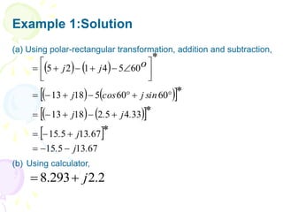
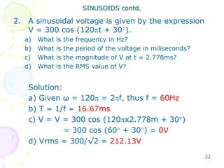
Evaluate the following complex numbers:
o
o
o
j
j
b
j
j
a
30
10
)]
4
3
/(
)
40
3
5
10
.[(
*
]
60
5
)
4
1
)(
2
5
.[(












Example 1:Solution
   
   
 
   
 
 
67
13
5
15
67
13
5
15
33
4
5
2
18
13
60
60
5
18
13
60
5
4
1
2
5
.
j
.
.
j
.
.
j
.
j
sin
j
cos
j
j
j
*
*
*
*
o






























(a) Using polar-rectangular transformation, addition and subtraction,
(b) Using calculator,
2
.
2
293
.
8 j


Example 2
Transform these sinusoids to phasors:
 V
t
v
b
A
t
i
a







50
30
sin
4
)
(
)
40
50
cos(
6
)
(
Example 2: Solution
Refer to sinusoids to phasors transformation table:
a)
b) Since
so
A
40
6
I 



 
   
 V
140
t
30
cos
4
90
50
t
30
cos
4
50
t
30
sin
4
v
90
A
cos
A
sin
















V
140
4
V 


Example 3
Given y1 = 20 cos (100t - 30) and y2 = 40 cos (100t + 60). Express
y1 + y2 as a single cosine function.
Solution:
In phasor form
Thus, y1 + y2 = 44.72 cos (100t + 33.4)

























4
.
33
72
.
44
64
.
24
32
.
37
64
.
34
20
10
32
.
17
60
40
30
20
60
40
&
30
20
2
1
2
1
j
j
j
y
y
y
y
Circuit Elements in Phasor Domain
 Circuit analysis is much simpler if it is done in phasor domain.
 In order to perform the phasor domain analysis, we need to
transform all circuit elements to its phasor equivalent.
 Transform the voltage-current relationship from time domain to
the frequency domain for each element.
Phasor Relationships for Resistor
 If current through resistor is:
 The voltage across R is V=IR (Ohm’s Law); in phasor form:
 But; phasor representation of the current is:
 Hence: V=RI







m
m
I
I
t
I
i )
cos(


 m
RI
V


m
I
I =
Phasor domain
Ohm’s Law in phasor form
Time domain Phasor domain
Phasor Relationships for Inductor
 If current through inductor is:
 The voltage across the inductor:
 Which transforms to the phasor
 But
 Hence


m
I
I =
)
t
cos(
LI
)
t
sin(
LI
dt
di
L
v m
m 






 90






90


 
 m
LI
V
)
cos( 
 
 t
I
i m
LI
j
LI
j
V m 

 


Time domain Phasor domain
The current and voltage are 90o out of
phase (voltage leads current by 90o)
Phasor Relationships for Capacitor
 Given voltage through capacitor is:
 The current through capacitor is:
 But
 Thus: where
 And
)
cos( 
 
 t
V
v m
dt
dv
C
i 
)
90
cos(
)
sin( 




 




 t
CV
t
CV
i m
m
90


 
 m
CV
I
90
1

j
CV
j
CV
j
I m 

 

 

m
V
)
/( C
j
I
V 

Time domain Phasor domain
Voltage – Current Relationships
Element Time domain
Frequency domain
R
L
C
Ri
v 
dt
di
L
v 
dt
dv
C
i 
RI
V 
LI
j
V 

C
j
I
V


Example 4
a) If voltage v = 10 cos (100t + 30⁰) is applied to a 50μF capacitor,
calculate the current through the capacitor.
b) What is the voltage across a 2μF capacitor when the current
through it is i = 4 sin (106t + 25⁰) A?
Ans:
a) 50 cos (100t + 120⁰) mA
b) 2 sin (106t - 65⁰) V
Impedance
 Previously:
 In terms of the ratio of the phasor voltage to the phasor current:
 Ohm’s Law in phasor form for any type of element
C
j
I
V
,
LI
j
V
,
RI
V

 


C
j
I
V
L
j
I
V
R
I
V


1
,
, 


ZI
V
or
,
I
V
Z 

Impedances and Admittances of Passive
Elements
Element Impedance
Admittance
R
L
C
R
Z
L
j
Z 

C
j
1
Z


R
1
Y 
L
j
1
Y


C
j
Y 

Equivalent circuits at dc and high
frequencies
Impedance in Rectangular Form
 The impedance may be expressed in rectangular form as
 where R = Re Z is the resistance and X = Im Z is the reactance.
 The impedance is inductive when X is positive or capacitive
when X is negative.
 The impedance may be also be expressed in polar form as
jX
R
Z 



 Z
Z
 where
 and




 Z
jX
R
Z
R
X
tan
,
X
R
Z 1
2
2 


 

 sin
Z
X
,
cos
Z
R 

Impedance Combinations
 Consider the N series-connected
impedances shown in figure.
 The same current I flows through
the impedances.
 Applying KVL around the loop gives
 The equivalent impedance at the input terminals is
or
)
Z
...
Z
Z
(
I
V
...
V
V
V N
2
1
N
2
1 +
+
+
=
+
+
+
=
N
2
1
eq Z
...
Z
Z
I
V
Z +
+
+
=
= N
2
1
eq Z
...
Z
Z
Z +
+
+
=
Voltage Divider of Series Circuit
 If N = 2, the current through the
impedances is
 Since V1 = Z1I and V2 = Z2I ,
then:
2
1 Z
Z
V
I
+
=
V
Z
Z
Z
V
,
V
Z
Z
Z
V
2
1
2
2
2
1
1
1
+
=
+
=
Parallel Circuit
 We can obtain the equivalent impedance or admittance of the N
parallel-connected impedances shown in figure.
 The cross voltage each impedance is the same.
Parallel Circuit
 Applying KCL at the top node
 The equivalent impedance is
 And the equivalent admittance is
N
2
1
eq
Z
1
...
Z
1
Z
1
V
1
Z
1





N
2
1
eq
Y
....
Y
Y
Y 



)
Z
1
...
Z
1
Z
1
(
V
I
...
I
I
I
N
2
1
N
2
1








Current Divider of Parallel Circuit
 Eg: When N = 2, as shown in Figure
5.19, the equivalent impedance
becomes
 since V = IZeq=I1Z1=I2Z2 the currents
in the impedances are
2
1
2
1
2
1
2
1
eq
eq
Z
Z
Z
Z
Z
/
1
Z
/
1
1
Y
Y
1
Y
1
Z







I
Z
Z
Z
I
,
I
Z
Z
Z
I
2
1
1
2
2
1
2
1




Example 5
Find the input impedance of the circuit in figure below. Assume that
the circuit operates at =50rad/s.
Example 6
Find Zeq in the circuit.
Ans: Zeq = 1 + j0.5 Ω
Example 7
Find v(t) and i(t) in the circuit of Figure below.

5
0.1F
+
v
-
Vs = 10 cos 4t
i
Example 7: Solution
vs =10 cos 4t → Vs =
The impedance is
Hence the current
V
0
10 



5
.
2
j
5
1
.
0
4
j
1
5
C
j
1
5
Z 






A
57
.
26
789
.
1
8
.
0
j
6
.
1
5
.
2
j
5
0
10
Z
V
I s










Example 7: Solution cont
Hence the voltage across the capacitor
Converting I and V to the time domain,
V
j
C
j
I
IZ
V C 








 43
.
63
47
.
4
1
.
0
4
57
.
26
789
.
1

   
   V
43
.
63
t
4
cos
47
.
4
t
v
A
57
.
26
t
4
cos
789
.
1
t
i






Example 8
Determine v(t) and i(t).
+
v
-
+
-
4Ω
i
0.2H
vs = 20 sin (10t + 30⁰) V
Ans: i(t) = 4.472 cos (4t+3.43⁰) A
v(t) = 8.944 cos (4t+93.43⁰) V
Chapter Summary

Chapter 3: AC Sources and AC Characteristic

  • 1.
    BEKG 1123 PRINCIPLES OFELECTRIC & ELECTRONICS
  • 2.
  • 3.
    AC Source Learning Outcome •In this part, we will cover on: 4.1 Waveform type 4.2 AC characteristic 3
  • 4.
    4 • AC isan electrical current whose magnitude and direction vary sinusoidally with time. • Such as current reverses at regular time intervals and has alternately positive and negative values. INTRODUCTION
  • 5.
    5 • The circuitsanalysis is considering the time- varying voltage source or current source. • Circuits driven by sinusoidal current or voltage sources are called ac circuits. • A sinusoid can be express in either sine or cosine form. INTRODUCTION..cont
  • 6.
    Difference between DCand AC DC AC 6 V 5V 1kHz R I V/I t V 5V I R V/I t
  • 7.
    AC Characteristics 7 • ACsignals are generated by: – AC generator – Electronic function generator • Types of AC waveforms: – Sine wave – Square wave – Triangle wave – Saw-tooth wave
  • 8.
    Characteristics of sinewave 8 • The sinusoidal waveform (sine wave) is the fundamental of AC current and AC voltage waveform.
  • 9.
    Characteristics of sinewave 9 • Sine waves are characterized by the amplitude and period of waveform. • Amplitude: – Is the maximum value of voltage or current. • Period: – Is time interval for 1 complete cycle. 0 V 10 V -10 V 15 V -15 V -20 V t ( s)  0 25 37.5 50.0 20 V The amplitude (A) of this sine wave is 20 V The period is 50.0 s A T
  • 10.
    Characteristics of sinewave 10 • The period of a sine wave can be measured between any two corresponding points on the waveform. T T T T T T A By contrast, the amplitude of a sine wave is only measured from the center to the maximum point.
  • 11.
    Characteristics of sinewave 11 • Frequency: – Frequency ( f ) is the number of cycles that a sine wave completes in one second. – Frequency is measured in hertz (Hz). • Example: 3.0 Hz If 3 cycles of a wave occur in one second, the frequency is 1.0 s
  • 12.
    Characteristics of sinewave 12 • Relationship between period and frequency – The period and frequency are reciprocals of each other. – Frequency = 1/ time for 1 complete cycle • Examples: – If the period is 50 s, what is the frequency? – If frequency is 60Hz, what is the period? and f T 1  T f 1 
  • 13.
    13 Waveform Terms & Definitions Definitions: Period– the time taken to complete a cycle, T (s) Peak value – the maximum instantaneous value measured from its zero value, Vp @ Vm (V) Peak-to-peak value – the maximum variation between the maximum positive instantaneous value and the maximum negative value, Vp-p (V) Instantaneous voltage / current - has a value that corresponds to a specific time t. Every waveform has an infinity number of instantaneous values. Such a waveform is described as the parameter as a function of time. In the case of a voltage it will be written as v(t). Cycle – the portion of a waveform contained in one period of time. For a sine wave, it is the complete event starting with a rise from zero energy to a maximum amplitude, its return to zero, the rise to a maximum in the opposite direction, and then its return to zero.
  • 14.
    14 WAVEFORM TERMS &DEFINITIONS contd.
  • 15.
    15 Sinusoids • Consider theexpression of a sinusoidal voltage where   ( ) sin m v t V t   = the amplitude of the sinusoid = the angular frequency in radians/s = the argument of the sinusoid m V t
  • 16.
    16 • The sinusoidrepeats itself every T seconds, thus T is called the period of the sinusoid or the time taken to complete one cycle. (s) SINUSOIDS contd.
  • 17.
    17 • The numberof cycles per second is called frequency, f. (Hz) • Angular frequency, ω. (rad/s) • An important value of the sinusoidal function is its RMS (root-mean-square) value. SINUSOIDS contd. 1 f T  2 f      2 m RMS dc V V V
  • 18.
    18 • Note: Radianmeasure – ω is usually expressed in radian/s – 2 radians = 360 – to convert from degrees to radians, multiply by /180. – to convert from radians to degrees, multiply by 180/. • From the general expression of the sinusoidal voltage, we can find the value of voltage at any given instant of time. SINUSOIDS contd.
  • 19.
    19 • If thewaveform does not pass through zero at t=0, it has a phase shift. • For a waveform shifted left, • For waveform shifted right, where       ( ) sin m v t V t  = phase angle of the sinusoid function SINUSOIDS contd.       ( ) sin m v t V t
  • 20.
  • 21.
    21 Example: 1. Find theamplitude, phase, period and frequency of the sinusoid Solution: Amplitude, Vm = 12V Phase, = 10˚ Angular frequency, ω = 50rad/s thus the period, T = The frequency, f = SINUSOIDS contd.  2 2 50 0.1257s      7.958 1 z T H       ( ) 12sin 50 10 v t t
  • 22.
    22 2. A sinusoidalvoltage is given by the expression V = 300 cos (120t + 30). a) What is the frequency in Hz? b) What is the period of the voltage in miliseconds? c) What is the magnitude of V at t = 2.778ms? d) What is the RMS value of V? Solution: a) Given ω = 120 = 2f, thus f = 60Hz b) T = 1/f = 16.67ms c) V = V = 300 cos (120x2.778m + 30) = 300 cos (60 + 30) = 0V d) Vrms = 300/√2 = 212.13V SINUSOIDS contd.
  • 23.
    23 • Consider thefollowing: SINUSOIDS contd. 1( ) sin m v t V t     2( ) sin m v t V t    
  • 24.
    24 • The v2is occurred first in time. • Thus it can be said that v2 leads v1 by or v1 lags v2 by . • If ≠ 0 we can say v1 and v2 are out of phase. • If = 0 we can say v1 and v2 are in phase. • v1 and v2 can be compared in this manner because they operate at the same frequency (do not need to have the same amplitude). SINUSOIDS contd.    
  • 25.
    25 • Transformation betweencosine and sine form Converting from negative to positive magnitude where SINUSOIDS contd. sin cos( 90 ) cos sin( 90 ) A A A A       sin sin( 180 ) cos cos( 180 ) A A A A         A t    
  • 26.
    26 Example: 1. For thefollowing sinusoidal voltage, find the value v at t = 0s and t = 0.5s. v = 6 cos (100t + 60˚) Solution: Note: both ωt and must be in same unit before adding them up. SINUSOIDS contd. at t = 0.5s v = 6 cos (50 rad +60˚) = 4.26V at t = 0s v = 6 cos (0+60˚) = 3V 
  • 27.
    27 2. Calculate thephase angle between v1 = -10 cos (ωt + 50) v2 = 12 sin (ωt - 10) State which sinusoid is leading. Solution: In order to compare v1 and v2, we must express them in the same form (either in cosine or sine function) with positive magnitude. Note: the value of must be between 0 to 180 v1 = -10 cos (ωt + 50) = 10 cos (ωt + 50 - 180) = 10 cos (ωt - 130) SINUSOIDS contd. 
  • 28.
    28 and v2 = 12sin (ωt - 10) = 12 cos (ωt - 10 - 90) = 12 cos (ωt - 100) the equation v2 can be written in the following form v2 = 12 cos (ωt - 130 + 30) ‘+30’ in the above expression means v2 leads v1 by 30 SINUSOIDS contd.
  • 29.
    AC Charateristic Learning Outcomes Atthe end of this part, students should be able to; 1. identify a sinusoidal waveform and measure its characteristics. 2. apply phasor to analyze alternating signals. 3. use a phasor to represent a sine wave.
  • 30.
    Introduction  A sinusoidis a signal that has the form of the sine or cosine function.  A sinusoidal current is usually referred to as alternating current (ac).  Such a current reverses at regular time intervals and has alternately positive and negative values.  AC circuits are the circuits driven by sinusoidal current or voltage sources.
  • 31.
  • 32.
  • 33.
    Average Value  Understandingthe average value using a sand analogy:  The average height of the sand is that height obtained if the distance form one end to the other is maintained while the sand is leveled off.
  • 34.
    Average Value (cont) Thealgebraic sum of the areas must be determined, since some area contributions will be from below the horizontal axis. Area above the axis is assigned a positive sign and area below the axis is assigned a negative sign. The average value of any current or voltage is the value indicated on a dc meter – over a complete cycle the average value is the equivalent dc value.
  • 35.
    Effective (RMS) Value Effective value arises from the need to measure the effectiveness of the voltage or current source in delivering the power to resistive load.  Definition: Effective value of periodic current is the dc current that delivers the same average power to a resistor as the periodic current.  Effective value is given by ,  This indicates that effective value is the square root of the average of the square of the periodic signal. dt v T V T eff   0 2 1 dt i T I T eff   0 2 1
  • 36.
    Effective (RMS) Value(cont)  For the sinusoid the effective or rms value is  Similarly for      T m T m rms dt t T I tdt I T I 0 2 0 2 2 ) 2 cos 1 ( 2 1 cos 1   2 m rms I I  , cos ) ( t V t v m   2 m rms V V  , cos ) ( t I t i m  
  • 37.
    Phasors  Sinusoids areeasily expressed in terms of phasors.  A phasor is a complex number that represents the amplitude and phase of the sinusoid.  Complex number can be written in one of the following three forms: a. Rectangular form: b. Polar form: c. Exponential form: jy x z      r z  j re z 
  • 38.
     where: j = x= real part of z y = imaginary part of z r = the magnitude of z ϕ = the phase of z 1 
  • 39.
    Relationship between Rectangularand Polar Form 2 2 1 ; tan y r x y x      cos ; sin x r y r                cos sin z x jy r r j r or Thus, z may be written as, Note: addition and subtraction of complex number better perform in rectangular form. Multiplication and division in polar form.
  • 40.
    Basic Properties ofComplex Numbers Addition : Subtraction : Multiplication : Division : 2 1 2 1 2 1      r r z z 2 1 2 1 2 1      r r z z     2 1 2 1 2 1 y y j x x z z          2 1 2 1 2 1 y y j x x z z     
  • 41.
    Reciprocal : Square Root: Complex Conjugate : note: In general,     r z 1 1   2 /    r z     j re r jy x z         j j   1    sin j cos e j   
  • 42.
     As weknow, the sinusoidal voltage can be represented in sine or cosine function.  First, consider the cosine function as in:  This expression is in time domain.  In phasor method, we no longer consider in time domain instead in phasor domain (also known as frequency domain).   ( ) cos m v t V t    
  • 43.
     The cosinefunction will be represented in phasor and complex number such as:  For example: Transform the sinusoid: v(t) = 12 cos (377t - 60˚) thus,     ( ) cos cos sin m m m m v t V t V V j V            39 . 10 6 60 12 j v      or
  • 44.
     The phasorrepresentation carries only the amplitude and phase angle information.  The frequency term is dropped since we know that the frequency of the sinusoidal response is the same as the source.  The cosine expression is also dropped since we know that the response and source are both sinusoidal.
  • 45.
    Sinusoid-phasor Transformation Time-domain representationPhasor-domain Representation             cos sin 90 cos I sin I 90 m m m m m m m m V t V V t V I t I t                             * to get the phasor representation of a sinusoid, we express it in cosine form.
  • 46.
    and  Thus, thephasor diagram is:    m V V θ I I m - ∠ =
  • 47.
    Differentiation and Integration TimeDomain Phasor Domain dt dv V j vdt  j V
  • 48.
    Example 1 Evaluate thefollowing complex numbers: o o o j j b j j a 30 10 )] 4 3 /( ) 40 3 5 10 .[( * ] 60 5 ) 4 1 )( 2 5 .[(            
  • 49.
    Example 1:Solution                  67 13 5 15 67 13 5 15 33 4 5 2 18 13 60 60 5 18 13 60 5 4 1 2 5 . j . . j . . j . j sin j cos j j j * * * * o                               (a) Using polar-rectangular transformation, addition and subtraction, (b) Using calculator, 2 . 2 293 . 8 j  
  • 50.
    Example 2 Transform thesesinusoids to phasors:  V t v b A t i a        50 30 sin 4 ) ( ) 40 50 cos( 6 ) (
  • 51.
    Example 2: Solution Referto sinusoids to phasors transformation table: a) b) Since so A 40 6 I            V 140 t 30 cos 4 90 50 t 30 cos 4 50 t 30 sin 4 v 90 A cos A sin                 V 140 4 V   
  • 52.
    Example 3 Given y1= 20 cos (100t - 30) and y2 = 40 cos (100t + 60). Express y1 + y2 as a single cosine function. Solution: In phasor form Thus, y1 + y2 = 44.72 cos (100t + 33.4)                          4 . 33 72 . 44 64 . 24 32 . 37 64 . 34 20 10 32 . 17 60 40 30 20 60 40 & 30 20 2 1 2 1 j j j y y y y
  • 53.
    Circuit Elements inPhasor Domain  Circuit analysis is much simpler if it is done in phasor domain.  In order to perform the phasor domain analysis, we need to transform all circuit elements to its phasor equivalent.  Transform the voltage-current relationship from time domain to the frequency domain for each element.
  • 54.
    Phasor Relationships forResistor  If current through resistor is:  The voltage across R is V=IR (Ohm’s Law); in phasor form:  But; phasor representation of the current is:  Hence: V=RI        m m I I t I i ) cos(    m RI V   m I I = Phasor domain Ohm’s Law in phasor form
  • 55.
  • 56.
    Phasor Relationships forInductor  If current through inductor is:  The voltage across the inductor:  Which transforms to the phasor  But  Hence   m I I = ) t cos( LI ) t sin( LI dt di L v m m         90       90      m LI V ) cos(     t I i m LI j LI j V m      
  • 57.
    Time domain Phasordomain The current and voltage are 90o out of phase (voltage leads current by 90o)
  • 58.
    Phasor Relationships forCapacitor  Given voltage through capacitor is:  The current through capacitor is:  But  Thus: where  And ) cos(     t V v m dt dv C i  ) 90 cos( ) sin(             t CV t CV i m m 90      m CV I 90 1  j CV j CV j I m         m V ) /( C j I V  
  • 59.
  • 60.
    Voltage – CurrentRelationships Element Time domain Frequency domain R L C Ri v  dt di L v  dt dv C i  RI V  LI j V   C j I V  
  • 61.
    Example 4 a) Ifvoltage v = 10 cos (100t + 30⁰) is applied to a 50μF capacitor, calculate the current through the capacitor. b) What is the voltage across a 2μF capacitor when the current through it is i = 4 sin (106t + 25⁰) A? Ans: a) 50 cos (100t + 120⁰) mA b) 2 sin (106t - 65⁰) V
  • 62.
    Impedance  Previously:  Interms of the ratio of the phasor voltage to the phasor current:  Ohm’s Law in phasor form for any type of element C j I V , LI j V , RI V      C j I V L j I V R I V   1 , ,    ZI V or , I V Z  
  • 63.
    Impedances and Admittancesof Passive Elements Element Impedance Admittance R L C R Z L j Z   C j 1 Z   R 1 Y  L j 1 Y   C j Y  
  • 64.
    Equivalent circuits atdc and high frequencies
  • 65.
    Impedance in RectangularForm  The impedance may be expressed in rectangular form as  where R = Re Z is the resistance and X = Im Z is the reactance.  The impedance is inductive when X is positive or capacitive when X is negative.  The impedance may be also be expressed in polar form as jX R Z      Z Z
  • 66.
     where  and     Z jX R Z R X tan , X R Z 1 2 2        sin Z X , cos Z R  
  • 67.
    Impedance Combinations  Considerthe N series-connected impedances shown in figure.  The same current I flows through the impedances.  Applying KVL around the loop gives  The equivalent impedance at the input terminals is or ) Z ... Z Z ( I V ... V V V N 2 1 N 2 1 + + + = + + + = N 2 1 eq Z ... Z Z I V Z + + + = = N 2 1 eq Z ... Z Z Z + + + =
  • 68.
    Voltage Divider ofSeries Circuit  If N = 2, the current through the impedances is  Since V1 = Z1I and V2 = Z2I , then: 2 1 Z Z V I + = V Z Z Z V , V Z Z Z V 2 1 2 2 2 1 1 1 + = + =
  • 69.
    Parallel Circuit  Wecan obtain the equivalent impedance or admittance of the N parallel-connected impedances shown in figure.  The cross voltage each impedance is the same.
  • 70.
    Parallel Circuit  ApplyingKCL at the top node  The equivalent impedance is  And the equivalent admittance is N 2 1 eq Z 1 ... Z 1 Z 1 V 1 Z 1      N 2 1 eq Y .... Y Y Y     ) Z 1 ... Z 1 Z 1 ( V I ... I I I N 2 1 N 2 1        
  • 71.
    Current Divider ofParallel Circuit  Eg: When N = 2, as shown in Figure 5.19, the equivalent impedance becomes  since V = IZeq=I1Z1=I2Z2 the currents in the impedances are 2 1 2 1 2 1 2 1 eq eq Z Z Z Z Z / 1 Z / 1 1 Y Y 1 Y 1 Z        I Z Z Z I , I Z Z Z I 2 1 1 2 2 1 2 1    
  • 72.
    Example 5 Find theinput impedance of the circuit in figure below. Assume that the circuit operates at =50rad/s.
  • 73.
    Example 6 Find Zeqin the circuit. Ans: Zeq = 1 + j0.5 Ω
  • 74.
    Example 7 Find v(t)and i(t) in the circuit of Figure below.  5 0.1F + v - Vs = 10 cos 4t i
  • 75.
    Example 7: Solution vs=10 cos 4t → Vs = The impedance is Hence the current V 0 10     5 . 2 j 5 1 . 0 4 j 1 5 C j 1 5 Z        A 57 . 26 789 . 1 8 . 0 j 6 . 1 5 . 2 j 5 0 10 Z V I s          
  • 76.
    Example 7: Solutioncont Hence the voltage across the capacitor Converting I and V to the time domain, V j C j I IZ V C           43 . 63 47 . 4 1 . 0 4 57 . 26 789 . 1         V 43 . 63 t 4 cos 47 . 4 t v A 57 . 26 t 4 cos 789 . 1 t i      
  • 77.
    Example 8 Determine v(t)and i(t). + v - + - 4Ω i 0.2H vs = 20 sin (10t + 30⁰) V Ans: i(t) = 4.472 cos (4t+3.43⁰) A v(t) = 8.944 cos (4t+93.43⁰) V
  • 78.