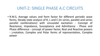
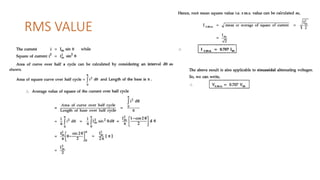
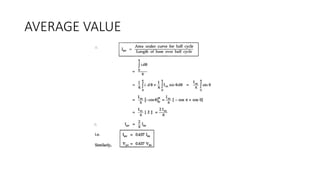
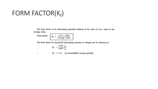
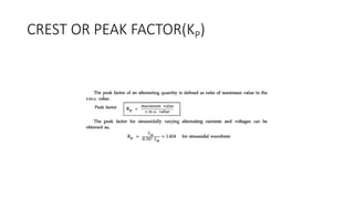
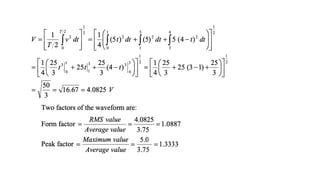
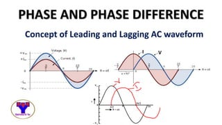
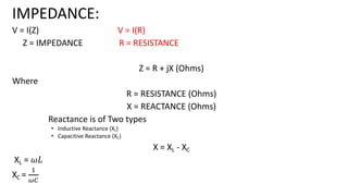
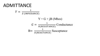
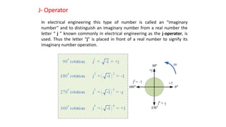
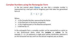
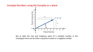
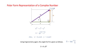
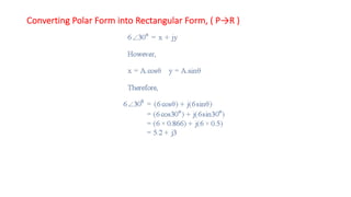
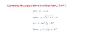
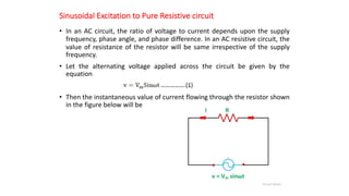
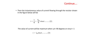
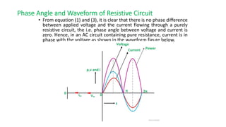
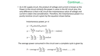
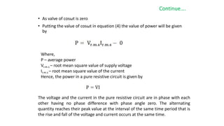
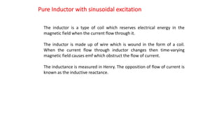
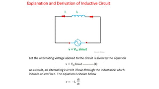
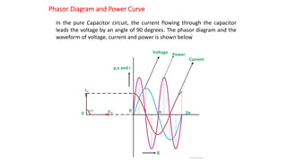
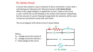
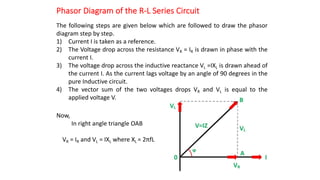
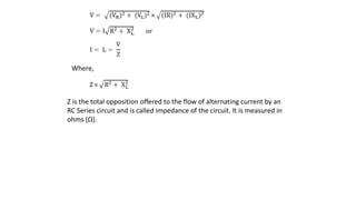
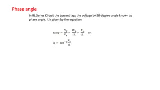
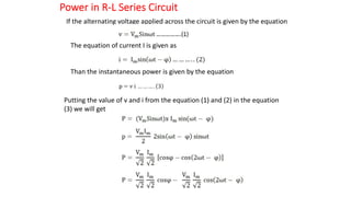
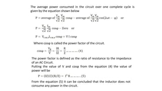
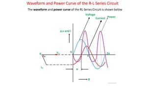
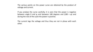
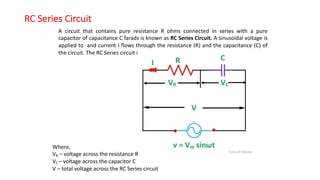
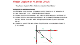
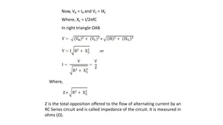
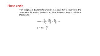
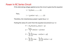
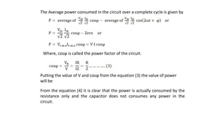
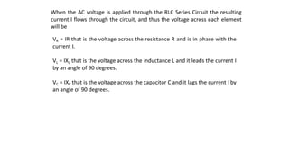
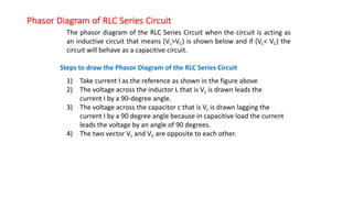
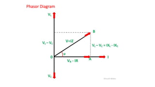
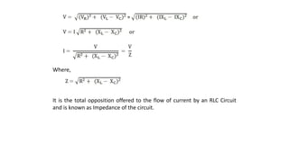
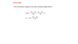
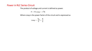
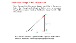
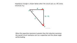
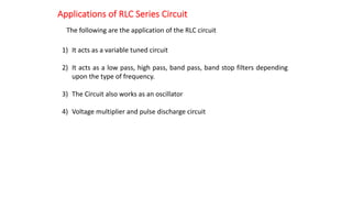
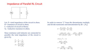
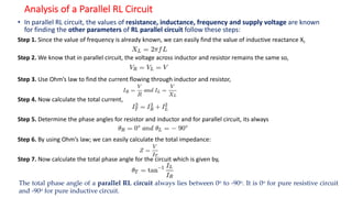
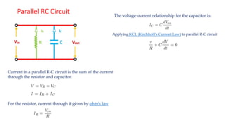
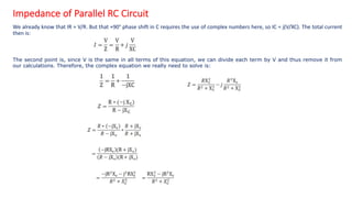
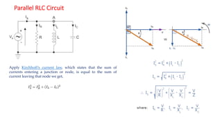
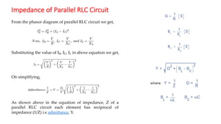
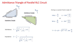
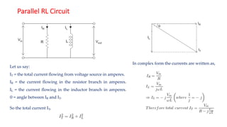
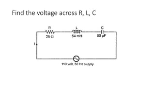
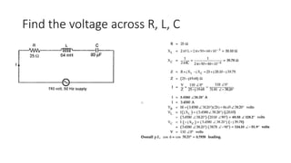
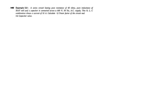
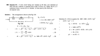
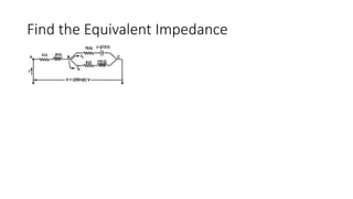
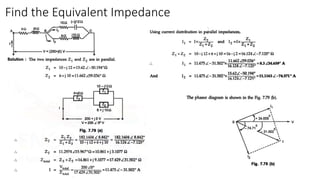
SINGLE PHASE A.C CIRCUITS
Sainadh Singh Kshatri
UNIT-2: SINGLE PHASE A.C CIRCUITS
• R.M.S, Average values and form factor for different periodic wave
forms, Steady state analysis of R, L and C (in series, parallel and series
parallel combinations) with sinusoidal excitation - Concept of
Reactance, Impedance, Susceptance and Admittance - Phase and
Phase difference - concept of power factor, Real and Reactive powers
- j-notation, Complex and Polar forms of representation, Complex
power
Basics of Sine Wave
𝑥!"# =
1
𝑇
%
$
%
𝑥 𝑡 𝑑𝑡
𝑥&'( =
)
%
∫
$
%
𝑥* 𝑡 𝑑𝑡
Form Factor =
𝐑𝐌𝐒 𝐕𝐚𝐥𝐮𝐞
𝐀𝐯𝐞𝐫𝐚𝐠𝐞 𝐕𝐚𝐥𝐮𝐞
Peak Factor =
𝐏𝐞𝐚𝐤 𝐕𝐚𝐥𝐮𝐞
𝐑𝐌𝐒 𝐕𝐚𝐥𝐮𝐞
RMS VALUE AND AVERAGE VALUE OF SINE WAVE
RMS VALUE
AVERAGE VALUE
FORM FACTOR(Kf)
CREST OR PEAK FACTOR(KP)
Phase
The development of an AC quantity through different stages as known
as phase.
(or)
Phase is the angular measure of alternating quantity.
• In-Phase:
When two alternating quantities reach their maximum and minimum
simultaneously, then these quantities are called as in-phase.
• Out of Phase:
When two alternating quantities do not attain their maximum and
minimum values simultaneously then they are at out of phase. It is also
known as Phase difference
Phase and Phase Difference
IMPEDANCE:
V = I(Z) V = I(R)
Z = IMPEDANCE R = RESISTANCE
Z = R + jX (Ohms)
Where
R = RESISTANCE (Ohms)
X = REACTANCE (Ohms)
Reactance is of Two types
• Inductive Reactance (XL)
• Capacitive Reactance (XC)
X = XL - XC
XL = 𝜔𝐿
XC =
!
"#
ADMITTANCE
𝑌 =
!
" ($%&'()*+')
Y = G + jB (Mhos)
𝐺 =
!
-(-'.$./)*+')
Conductance
B=
!
0(-')+/)*+')
Susceptance
J- Operator
In electrical engineering this type of number is called an “imaginary
number” and to distinguish an imaginary number from a real number the
letter “ j ” known commonly in electrical engineering as the j-operator, is
used. Thus the letter “j” is placed in front of a real number to signify its
imaginary number operation.
Complex Numbers using the Rectangular Form
In the last tutorial about Phasors, we saw that a complex number is
represented by a real part and an imaginary part that takes the generalised
form of:
Where:
Z - is the Complex Number representing the Vector
x - is the Real part or the Active component
y - is the Imaginary part or the Reactive component
j - is defined by √-1
In the rectangular form, a complex number can be represented as a point on
a two dimensional plane called the complex or s-plane. So for
example, Z = 6 + j4 represents a single point whose coordinates represent 6
on the horizontal real axis and 4 on the vertical imaginary axis as shown.
Complex Numbers using the Complex or s-plane
But as both the real and imaginary parts of a complex number in the
rectangular form can be either a positive number or a negative number
Polar Form Representation of a Complex Number
Using trigonometry again, the angle θ of A is given as follows.
Z = A ∠θ“
Converting Polar Form into Rectangular Form, ( P→R )
Converting Rectangular Form into Polar Form, ( R→P )
Sinusoidal Excitation to Pure Resistive circuit
• In an AC circuit, the ratio of voltage to current depends upon the supply
frequency, phase angle, and phase difference. In an AC resistive circuit, the
value of resistance of the resistor will be same irrespective of the supply
frequency.
• Let the alternating voltage applied across the circuit be given by the
equation
• Then the instantaneous value of current flowing through the resistor shown
in the figure below will be
Continue….
• Then the instantaneous value of current flowing through the resistor shown
in the figure below will be
The value of current will be maximum when ωt= 90 degrees or sinωt = 1
Phase Angle and Waveform of Resistive Circuit
• From equation (1) and (3), it is clear that there is no phase difference
between applied voltage and the current flowing through a purely
resistive circuit, the i.e. phase angle between voltage and current is
zero. Hence, in an AC circuit containing pure resistance, current is in
phase with the voltage as shown in the waveform figure below.
Continue….
• As in DC supply circuit, the product of voltage and current is known as the
Power in the circuit similarly the power is same in the AC circuit also, the
only difference is that in AC circuit the instantaneous value of voltage and
current is taken into consideration. Therefore, the instantaneous power in a
purely resistive circuit is given by the equation shown below
Instantaneous power, p= vi
The average power consumed in the circuit over a complete cycle is given by
Continue….
• As valve of cosωt is zero
• Putting the value of cosωt in equation (4) the value of power will be given
by
Where,
P – average power
Vr.m.s – root mean square value of supply voltage
Ir.m.s – root mean square value of the current
Hence, the power in a pure resistive circuit is given by
The voltage and the current in the pure resistive circuit are in phase with each
other having no phase difference with phase angle zero. The alternating
quantity reaches their peak value at the interval of the same time period that is
the rise and fall of the voltage and current occurs at the same time.
Pure Inductor with sinusoidal excitation
The inductor is a type of coil which reserves electrical energy in the
magnetic field when the current flow through it.
The inductor is made up of wire which is wound in the form of a coil.
When the current flow through inductor changes then time-varying
magnetic field causes emf which obstruct the flow of current.
The inductance is measured in Henry. The opposition of flow of current is
known as the inductive reactance.
Explanation and Derivation of Inductive Circuit
Let the alternating voltage applied to the circuit is given by the equation
As a result, an alternating current i flows through the inductance which
induces an emf in it. The equation is shown below
The emf which is induced in the circuit is equal and opposite to the applied
voltage. Hence, the equation becomes
Putting the value of e in equation (2) we will get the equation as
Integrating both sides of the equation (3), we will get
where, XL = ω L is the opposition offered to the flow of
alternating current by a pure inductance and is called
inductive reactance.
The value of current will be maximum when sin (ωt – π/2) = 1
Therefore,
Substituting this value in Im from the equation (5) and putting it in
equation (4) we will get
Phasor Diagram and Power Curve of Inductive Circuit
Power in Pure Inductive Circuit
Instantaneous power in the inductive circuit is given by
Hence, the average power consumed in a purely inductive circuit is zero.
The average power in one alteration, i.e., in a half cycle is zero, as the
negative and positive loop is under power curve is the same.
Sinusoidal excitation with pure capacitor
When the DC voltage is applied across the capacitor, then the electric field is
developed across the plates of the capacitor and no current flow between
them. If the variable voltage source is applied across the capacitor plates
then the ongoing current flow through the source due to the charging and
discharging of the capacitor.
Explanation and derivation of Capacitor Circuit
A capacitor consists of two insulating plates which are separated by a
dielectric medium. It stores energy in electrical form. The capacitor works
as a storage device, and it gets charged when the supply in ON and gets
discharged when the supply is OFF. If it is connected to the direct supply, it
gets charged equal to the value of the applied voltage.
Let the alternating voltage applied to the circuit is given by the equation
Charge of the capacitor at any instant of time is given as
Current flowing through the circuit is given by the equation
Putting the value of q from the equation (2) in equation (3) we will get
Now, putting the value of v from the equation (1) in the equation (3) we
will get
Where Xc = 1/ωC is the opposition offered to the flow of alternating current by
a pure capacitor and is called Capacitive Reactance.
The value of current will be maximum when sin(ωt + π/2) = 1. Therefore, the
value of maximum current Im will be given as
Substituting the value of Im in the equation (4) we will get
Phasor Diagram and Power Curve
In the pure Capacitor circuit, the current flowing through the capacitor
leads the voltage by an angle of 90 degrees. The phasor diagram and the
waveform of voltage, current and power is shown below
Power in Pure Capacitor Circuit
Instantaneous power is given by p = vi
Hence, from the above equation, it is clear that the average power in
the Capacitive circuit is zero.
The average power in a half cycle is zero as the positive and negative loop
area in the waveform shown are same. In the first quarter cycle, the
power which is supplied by the source is stored in the electric field set up
between the capacitor plates. In the another or next quarter cycle, the
electric field diminishes, and thus the power stored in the field is
returned to the source. This process is repeated continuously and,
therefore, no power is consumed by the Capacitor circuit.
R-L Series Circuit
A circuit that contains a pure resistance R ohms connected in series with a
coil having pure inductance of L (Henry) is known as R L Series Circuit.
When an AC supply voltage V is applied the current, I flows in the circuit.
IR and IL will be the current flowing in the resistor and inductor respectively,
but the amount of current flowing through both the elements will be same
as they are connected in series with each other.
The circuit diagram of RL Series Circuit is shown below
Where,
VR – voltage across the resistor R
VL – voltage across the inductor L
V – Total voltage of the circuit
Phasor Diagram of the R-L Series Circuit
The following steps are given below which are followed to draw the phasor
diagram step by step.
1) Current I is taken as a reference.
2) The Voltage drop across the resistance VR = IR is drawn in phase with the
current I.
3) The voltage drop across the inductive reactance VL =IXL is drawn ahead of
the current I. As the current lags voltage by an angle of 90 degrees in the
pure Inductive circuit.
4) The vector sum of the two voltages drops VR and VL is equal to the
applied voltage V.
Now,
In right angle triangle OAB
VR = IR and VL = IXL where XL = 2πfL
Where,
Z is the total opposition offered to the flow of alternating current by an
RC Series circuit and is called impedance of the circuit. It is measured in
ohms (Ω).
Phase angle
In RL Series Circuit the current lags the voltage by 90-degree angle known as
phase angle. It is given by the equation
Power in R-L Series Circuit
If the alternating voltage applied across the circuit is given by the equation
The equation of current I is given as
Than the instantaneous power is given by the equation
Putting the value of v and i from the equation (1) and (2) in the equation
(3) we will get
The average power consumed in the circuit over one complete cycle is
given by the equation shown below
Where cosϕ is called the power factor of the circuit.
The power factor is defined as the ratio of resistance to the impedance
of an AC Circuit.
Putting the value of V and cosϕ from the equation (4) the value of
power will be
From the equation (5) it can be concluded that the inductor does not
consume any power in the circuit.
Waveform and Power Curve of the R-L Series Circuit
The waveform and power curve of the RL Series Circuit is shown below
The various points on the power curve are obtained by the product of
voltage and current.
If you analyze the curve carefully, it is seen that the power is negative
between angle 0 and ϕ and between 180 degrees and (180 + ϕ) and
during the rest of the cycle the power is positive.
The current lags the voltage and thus they are not in phase with each
other.
RC Series Circuit
A circuit that contains pure resistance R ohms connected in series with a pure
capacitor of capacitance C farads is known as RC Series Circuit. A sinusoidal voltage is
applied to and current I flows through the resistance (R) and the capacitance (C) of
the circuit. The RC Series circuit is shown in the figure below
Where,
VR – voltage across the resistance R
VC – voltage across the capacitor C
V – total voltage across the RC Series circuit
Phasor Diagram of RC Series Circuit
The phasor diagram of the RC Series circuit is shown below
Steps to draw a Phasor Diagram
The following steps are used to draw the phasor diagram of RC Series circuit
1) Take the current I (r.m.s value) as a reference vector
2) Voltage drop in resistance VR = IR is taken in phase with the current vector
3) Voltage drop in capacitive reactance VC = IXC is drawn 90 degrees behind the
current vector, as current leads voltage by 90 degrees in pure capacitive
circuit)
4) The vector sum of the two voltage drops is equal to the applied voltage V
(r.m.s value).
Now, VR = IR and VC = IXC
Where, XC = I/2πfC
In right triangle OAB
Where,
Z is the total opposition offered to the flow of alternating current by an
RC Series circuit and is called impedance of the circuit. It is measured in
ohms (Ω).
Phase angle
From the phasor diagram shown above it is clear that the current in the
circuit leads the applied voltage by an angle ϕ and this angle is called the
phase angle.
Power in RC Series Circuit
If the alternating voltage applied across the circuit is given by the equation
Then,
Therefore, the instantaneous power is given by p = vi
Putting the value of v and i from the equation (1) and (2) in p = vi
The Average power consumed in the circuit over a complete cycle is given by
Where, cosϕ is called the power factor of the circuit.
Putting the value of V and cosϕ from the equation (3) the value of power
will be
From the equation (4) it is clear that the power is actually consumed by the
resistance only and the capacitor does not consumes any power in the
circuit.
Waveform and Power Curve of the RC Series Circuit
The waveform and power curve of the RC Circuit is shown below
The various points on the power curve is obtained from the product of
the instantaneous value of voltage and current.
The power is negative between the angle (180◦ – ϕ) and 180◦ and
between (360◦ -ϕ) and 360◦ and in the rest of the cycle the power is
positive.
Since the area under the positive loops is greater than that under the
negative loops, therefore the net power over a complete cycle is
positive.
R-L-C Series Circuit
The RLC Series Circuit is defined as when a pure resistance of R ohms, a
pure inductance of L Henry and a pure capacitance of C farads are
connected together in series combination with each other. As all the three
elements are connected in series so, the current flowing in each element
of the circuit will be same as the total current I flowing in the circuit.
In the RLC Series Circuit
XL = 2πfL and XC = 1/2πfC
When the AC voltage is applied through the RLC Series Circuit the resulting
current I flows through the circuit, and thus the voltage across each element
will be
VR = IR that is the voltage across the resistance R and is in phase with the
current I.
VL = IXL that is the voltage across the inductance L and it leads the current I
by an angle of 90 degrees.
VC = IXC that is the voltage across the capacitor C and it lags the current I by
an angle of 90 degrees.
Phasor Diagram of RLC Series Circuit
The phasor diagram of the RLC Series Circuit when the circuit is acting as
an inductive circuit that means (VL>VC) is shown below and if (VL< VC) the
circuit will behave as a capacitive circuit.
Steps to draw the Phasor Diagram of the RLC Series Circuit
1) Take current I as the reference as shown in the figure above
2) The voltage across the inductor L that is VL is drawn leads the
current I by a 90-degree angle.
3) The voltage across the capacitor c that is Vc is drawn lagging the
current I by a 90 degree angle because in capacitive load the current
leads the voltage by an angle of 90 degrees.
4) The two vector VL and VC are opposite to each other.
Phasor Diagram
Where,
It is the total opposition offered to the flow of current by an RLC Circuit
and is known as Impedance of the circuit.
Phase Angle
From the phasor diagram, the value of phase angle will be
Power in RLC Series Circuit
The product of voltage and current is defined as power.
Where cosϕ is the power factor of the circuit and is expressed as
The three cases of RLC Series Circuit
Case(i)
When XL > XC, the phase angle ϕ is positive. The circuit behaves as a
RL series circuit in which the current lags behind the applied
voltage and the power factor is lagging.
Case(ii)
When XL < XC, the phase angle ϕ is negative, and the circuit acts as
a series RC circuit in which the current leads the voltage by 90
degrees.
Case(iii)
When XL = XC, the phase angle ϕ is zero, as a result, the circuit
behaves like a purely resistive circuit. In this type of circuit, the
current and voltage are in phase with each other. The value of
power factor is unity.
Impedance Triangle of RLC Series Circuit
When the quantities of the phasor diagram are divided by the common
factor I then the right angle triangle is obtained known as impedance
triangle. The impedance triangle of the RL series circuit, when (XL > XC) is
shown below
If the inductive reactance is greater than the capacitive reactance than
the circuit reactance is inductive giving a lagging phase angle.
Impedance triangle is shown below when the circuit acts as a RC series
circuit (XL< XC)
When the capacitive reactance is greater than the inductive reactance
the overall circuit reactance acts as a capacitive and the phase angle
will be leading.
Applications of RLC Series Circuit
The following are the application of the RLC circuit
1) It acts as a variable tuned circuit
2) It acts as a low pass, high pass, band pass, band stop filters depending
upon the type of frequency.
3) The Circuit also works as an oscillator
4) Voltage multiplier and pulse discharge circuit
Impedance of Parallel RL Circuit
Let, Z = total impedance of the circuit in ohms.
R = resistance of circuit in ohms.
L = inductor of circuit in Henry.
XL = inductive reactance in ohms.
Since resistance and inductor are connected in
parallel, the total impedance of the circuit is
given by,
In order to remove “j” from the denominator multiply
and divide numerator and denominator by (R – j XL),
Analysis of a Parallel RL Circuit
• In parallel RL circuit, the values of resistance, inductance, frequency and supply voltage are known
for finding the other parameters of RL parallel circuit follow these steps:
Step 1. Since the value of frequency is already known, we can easily find the value of inductive reactance XL
Step 2. We know that in parallel circuit, the voltage across inductor and resistor remains the same so,
Step 3. Use Ohm’s law to find the current flowing through inductor and resistor,
Step 4. Now calculate the total current,
Step 5. Determine the phase angles for resistor and inductor and for parallel circuit, its always
Step 6. By using Ohm’s law; we can easily calculate the total impedance:
Step 7. Now calculate the total phase angle for the circuit which is given by,
The total phase angle of a parallel RL circuit always lies between 0o to -90o. It is 0o for pure resistive circuit
and -90o for pure inductive circuit.
Parallel RC Circuit
Current in a parallel R-C circuit is the sum of the current
through the resistor and capacitor.
For the resistor, current through it given by ohm’s law
The voltage-current relationship for the capacitor is:
Applying KCL (Kirchhoff’s Current Law) to parallel R-C circuit
Impedance of Parallel RC Circuit
We already know that IR = V/R. But that +90° phase shift in C requires the use of complex numbers here, so IC = j(V/XC). The total current
then is:
The second point is, since V is the same in all terms of this equation, we can divide each term by V and thus remove it from
our calculations. Therefore, the complex equation we really need to solve is:
Parallel RLC Circuit
Apply Kirchhoff’s current law, which states that the sum of
currents entering a junction or node, is equal to the sum of
current leaving that node we get,
Impedance of Parallel RLC Circuit
From the phasor diagram of parallel RLC circuit we get,
Substituting the value of IR, IC, IL in above equation we get,
On simplifying,
As shown above in the equation of impedance, Z of a
parallel RLC circuit each element has reciprocal of
impedance (1/Z) i.e admittance, Y.
Admittance Triangle of Parallel RLC Circuit
Giving us a power factor angle of:
Parallel RL Circuit
Let us say:
IT = the total current flowing from voltage source in amperes.
IR = the current flowing in the resistor branch in amperes.
IL = the current flowing in the inductor branch in amperes.
θ = angle between IR and IT.
So the total current IT,
In complex form the currents are written as,
Solved Problems
Find the voltage across R, L, C
Find the Equivalent Impedance
UNIT-II Material for BEE subject for B.Tech I Year

UNIT-II Material for BEE subject for B.Tech I Year

  • 1.
    SINGLE PHASE A.CCIRCUITS Sainadh Singh Kshatri
  • 2.
    UNIT-2: SINGLE PHASEA.C CIRCUITS • R.M.S, Average values and form factor for different periodic wave forms, Steady state analysis of R, L and C (in series, parallel and series parallel combinations) with sinusoidal excitation - Concept of Reactance, Impedance, Susceptance and Admittance - Phase and Phase difference - concept of power factor, Real and Reactive powers - j-notation, Complex and Polar forms of representation, Complex power
  • 3.
    Basics of SineWave 𝑥!"# = 1 𝑇 % $ % 𝑥 𝑡 𝑑𝑡 𝑥&'( = ) % ∫ $ % 𝑥* 𝑡 𝑑𝑡 Form Factor = 𝐑𝐌𝐒 𝐕𝐚𝐥𝐮𝐞 𝐀𝐯𝐞𝐫𝐚𝐠𝐞 𝐕𝐚𝐥𝐮𝐞 Peak Factor = 𝐏𝐞𝐚𝐤 𝐕𝐚𝐥𝐮𝐞 𝐑𝐌𝐒 𝐕𝐚𝐥𝐮𝐞
  • 4.
    RMS VALUE ANDAVERAGE VALUE OF SINE WAVE
  • 5.
  • 6.
  • 7.
  • 8.
    CREST OR PEAKFACTOR(KP)
  • 14.
    Phase The development ofan AC quantity through different stages as known as phase. (or) Phase is the angular measure of alternating quantity.
  • 15.
    • In-Phase: When twoalternating quantities reach their maximum and minimum simultaneously, then these quantities are called as in-phase. • Out of Phase: When two alternating quantities do not attain their maximum and minimum values simultaneously then they are at out of phase. It is also known as Phase difference
  • 16.
    Phase and PhaseDifference
  • 18.
    IMPEDANCE: V = I(Z)V = I(R) Z = IMPEDANCE R = RESISTANCE Z = R + jX (Ohms) Where R = RESISTANCE (Ohms) X = REACTANCE (Ohms) Reactance is of Two types • Inductive Reactance (XL) • Capacitive Reactance (XC) X = XL - XC XL = 𝜔𝐿 XC = ! "#
  • 19.
    ADMITTANCE 𝑌 = ! " ($%&'()*+') Y= G + jB (Mhos) 𝐺 = ! -(-'.$./)*+') Conductance B= ! 0(-')+/)*+') Susceptance
  • 20.
    J- Operator In electricalengineering this type of number is called an “imaginary number” and to distinguish an imaginary number from a real number the letter “ j ” known commonly in electrical engineering as the j-operator, is used. Thus the letter “j” is placed in front of a real number to signify its imaginary number operation.
  • 21.
    Complex Numbers usingthe Rectangular Form In the last tutorial about Phasors, we saw that a complex number is represented by a real part and an imaginary part that takes the generalised form of: Where: Z - is the Complex Number representing the Vector x - is the Real part or the Active component y - is the Imaginary part or the Reactive component j - is defined by √-1 In the rectangular form, a complex number can be represented as a point on a two dimensional plane called the complex or s-plane. So for example, Z = 6 + j4 represents a single point whose coordinates represent 6 on the horizontal real axis and 4 on the vertical imaginary axis as shown.
  • 22.
    Complex Numbers usingthe Complex or s-plane But as both the real and imaginary parts of a complex number in the rectangular form can be either a positive number or a negative number
  • 23.
    Polar Form Representationof a Complex Number Using trigonometry again, the angle θ of A is given as follows. Z = A ∠θ“
  • 24.
    Converting Polar Forminto Rectangular Form, ( P→R )
  • 25.
    Converting Rectangular Forminto Polar Form, ( R→P )
  • 26.
    Sinusoidal Excitation toPure Resistive circuit • In an AC circuit, the ratio of voltage to current depends upon the supply frequency, phase angle, and phase difference. In an AC resistive circuit, the value of resistance of the resistor will be same irrespective of the supply frequency. • Let the alternating voltage applied across the circuit be given by the equation • Then the instantaneous value of current flowing through the resistor shown in the figure below will be
  • 27.
    Continue…. • Then theinstantaneous value of current flowing through the resistor shown in the figure below will be The value of current will be maximum when ωt= 90 degrees or sinωt = 1
  • 28.
    Phase Angle andWaveform of Resistive Circuit • From equation (1) and (3), it is clear that there is no phase difference between applied voltage and the current flowing through a purely resistive circuit, the i.e. phase angle between voltage and current is zero. Hence, in an AC circuit containing pure resistance, current is in phase with the voltage as shown in the waveform figure below.
  • 29.
    Continue…. • As inDC supply circuit, the product of voltage and current is known as the Power in the circuit similarly the power is same in the AC circuit also, the only difference is that in AC circuit the instantaneous value of voltage and current is taken into consideration. Therefore, the instantaneous power in a purely resistive circuit is given by the equation shown below Instantaneous power, p= vi The average power consumed in the circuit over a complete cycle is given by
  • 30.
    Continue…. • As valveof cosωt is zero • Putting the value of cosωt in equation (4) the value of power will be given by Where, P – average power Vr.m.s – root mean square value of supply voltage Ir.m.s – root mean square value of the current Hence, the power in a pure resistive circuit is given by The voltage and the current in the pure resistive circuit are in phase with each other having no phase difference with phase angle zero. The alternating quantity reaches their peak value at the interval of the same time period that is the rise and fall of the voltage and current occurs at the same time.
  • 31.
    Pure Inductor withsinusoidal excitation The inductor is a type of coil which reserves electrical energy in the magnetic field when the current flow through it. The inductor is made up of wire which is wound in the form of a coil. When the current flow through inductor changes then time-varying magnetic field causes emf which obstruct the flow of current. The inductance is measured in Henry. The opposition of flow of current is known as the inductive reactance.
  • 32.
    Explanation and Derivationof Inductive Circuit Let the alternating voltage applied to the circuit is given by the equation As a result, an alternating current i flows through the inductance which induces an emf in it. The equation is shown below
  • 33.
    The emf whichis induced in the circuit is equal and opposite to the applied voltage. Hence, the equation becomes Putting the value of e in equation (2) we will get the equation as Integrating both sides of the equation (3), we will get
  • 34.
    where, XL =ω L is the opposition offered to the flow of alternating current by a pure inductance and is called inductive reactance. The value of current will be maximum when sin (ωt – π/2) = 1 Therefore, Substituting this value in Im from the equation (5) and putting it in equation (4) we will get
  • 35.
    Phasor Diagram andPower Curve of Inductive Circuit
  • 36.
    Power in PureInductive Circuit Instantaneous power in the inductive circuit is given by Hence, the average power consumed in a purely inductive circuit is zero. The average power in one alteration, i.e., in a half cycle is zero, as the negative and positive loop is under power curve is the same.
  • 37.
    Sinusoidal excitation withpure capacitor When the DC voltage is applied across the capacitor, then the electric field is developed across the plates of the capacitor and no current flow between them. If the variable voltage source is applied across the capacitor plates then the ongoing current flow through the source due to the charging and discharging of the capacitor.
  • 38.
    Explanation and derivationof Capacitor Circuit A capacitor consists of two insulating plates which are separated by a dielectric medium. It stores energy in electrical form. The capacitor works as a storage device, and it gets charged when the supply in ON and gets discharged when the supply is OFF. If it is connected to the direct supply, it gets charged equal to the value of the applied voltage.
  • 39.
    Let the alternatingvoltage applied to the circuit is given by the equation Charge of the capacitor at any instant of time is given as Current flowing through the circuit is given by the equation Putting the value of q from the equation (2) in equation (3) we will get Now, putting the value of v from the equation (1) in the equation (3) we will get
  • 40.
    Where Xc =1/ωC is the opposition offered to the flow of alternating current by a pure capacitor and is called Capacitive Reactance. The value of current will be maximum when sin(ωt + π/2) = 1. Therefore, the value of maximum current Im will be given as Substituting the value of Im in the equation (4) we will get
  • 41.
    Phasor Diagram andPower Curve In the pure Capacitor circuit, the current flowing through the capacitor leads the voltage by an angle of 90 degrees. The phasor diagram and the waveform of voltage, current and power is shown below
  • 42.
    Power in PureCapacitor Circuit Instantaneous power is given by p = vi Hence, from the above equation, it is clear that the average power in the Capacitive circuit is zero. The average power in a half cycle is zero as the positive and negative loop area in the waveform shown are same. In the first quarter cycle, the power which is supplied by the source is stored in the electric field set up between the capacitor plates. In the another or next quarter cycle, the electric field diminishes, and thus the power stored in the field is returned to the source. This process is repeated continuously and, therefore, no power is consumed by the Capacitor circuit.
  • 43.
    R-L Series Circuit Acircuit that contains a pure resistance R ohms connected in series with a coil having pure inductance of L (Henry) is known as R L Series Circuit. When an AC supply voltage V is applied the current, I flows in the circuit. IR and IL will be the current flowing in the resistor and inductor respectively, but the amount of current flowing through both the elements will be same as they are connected in series with each other. The circuit diagram of RL Series Circuit is shown below Where, VR – voltage across the resistor R VL – voltage across the inductor L V – Total voltage of the circuit
  • 44.
    Phasor Diagram ofthe R-L Series Circuit The following steps are given below which are followed to draw the phasor diagram step by step. 1) Current I is taken as a reference. 2) The Voltage drop across the resistance VR = IR is drawn in phase with the current I. 3) The voltage drop across the inductive reactance VL =IXL is drawn ahead of the current I. As the current lags voltage by an angle of 90 degrees in the pure Inductive circuit. 4) The vector sum of the two voltages drops VR and VL is equal to the applied voltage V. Now, In right angle triangle OAB VR = IR and VL = IXL where XL = 2πfL
  • 45.
    Where, Z is thetotal opposition offered to the flow of alternating current by an RC Series circuit and is called impedance of the circuit. It is measured in ohms (Ω).
  • 46.
    Phase angle In RLSeries Circuit the current lags the voltage by 90-degree angle known as phase angle. It is given by the equation
  • 47.
    Power in R-LSeries Circuit If the alternating voltage applied across the circuit is given by the equation The equation of current I is given as Than the instantaneous power is given by the equation Putting the value of v and i from the equation (1) and (2) in the equation (3) we will get
  • 48.
    The average powerconsumed in the circuit over one complete cycle is given by the equation shown below Where cosϕ is called the power factor of the circuit. The power factor is defined as the ratio of resistance to the impedance of an AC Circuit. Putting the value of V and cosϕ from the equation (4) the value of power will be From the equation (5) it can be concluded that the inductor does not consume any power in the circuit.
  • 49.
    Waveform and PowerCurve of the R-L Series Circuit The waveform and power curve of the RL Series Circuit is shown below
  • 50.
    The various pointson the power curve are obtained by the product of voltage and current. If you analyze the curve carefully, it is seen that the power is negative between angle 0 and ϕ and between 180 degrees and (180 + ϕ) and during the rest of the cycle the power is positive. The current lags the voltage and thus they are not in phase with each other.
  • 51.
    RC Series Circuit Acircuit that contains pure resistance R ohms connected in series with a pure capacitor of capacitance C farads is known as RC Series Circuit. A sinusoidal voltage is applied to and current I flows through the resistance (R) and the capacitance (C) of the circuit. The RC Series circuit is shown in the figure below Where, VR – voltage across the resistance R VC – voltage across the capacitor C V – total voltage across the RC Series circuit
  • 52.
    Phasor Diagram ofRC Series Circuit The phasor diagram of the RC Series circuit is shown below Steps to draw a Phasor Diagram The following steps are used to draw the phasor diagram of RC Series circuit 1) Take the current I (r.m.s value) as a reference vector 2) Voltage drop in resistance VR = IR is taken in phase with the current vector 3) Voltage drop in capacitive reactance VC = IXC is drawn 90 degrees behind the current vector, as current leads voltage by 90 degrees in pure capacitive circuit) 4) The vector sum of the two voltage drops is equal to the applied voltage V (r.m.s value).
  • 53.
    Now, VR =IR and VC = IXC Where, XC = I/2πfC In right triangle OAB Where, Z is the total opposition offered to the flow of alternating current by an RC Series circuit and is called impedance of the circuit. It is measured in ohms (Ω).
  • 54.
    Phase angle From thephasor diagram shown above it is clear that the current in the circuit leads the applied voltage by an angle ϕ and this angle is called the phase angle.
  • 55.
    Power in RCSeries Circuit If the alternating voltage applied across the circuit is given by the equation Then, Therefore, the instantaneous power is given by p = vi Putting the value of v and i from the equation (1) and (2) in p = vi
  • 56.
    The Average powerconsumed in the circuit over a complete cycle is given by Where, cosϕ is called the power factor of the circuit. Putting the value of V and cosϕ from the equation (3) the value of power will be From the equation (4) it is clear that the power is actually consumed by the resistance only and the capacitor does not consumes any power in the circuit.
  • 57.
    Waveform and PowerCurve of the RC Series Circuit The waveform and power curve of the RC Circuit is shown below
  • 59.
    The various pointson the power curve is obtained from the product of the instantaneous value of voltage and current. The power is negative between the angle (180◦ – ϕ) and 180◦ and between (360◦ -ϕ) and 360◦ and in the rest of the cycle the power is positive. Since the area under the positive loops is greater than that under the negative loops, therefore the net power over a complete cycle is positive.
  • 60.
    R-L-C Series Circuit TheRLC Series Circuit is defined as when a pure resistance of R ohms, a pure inductance of L Henry and a pure capacitance of C farads are connected together in series combination with each other. As all the three elements are connected in series so, the current flowing in each element of the circuit will be same as the total current I flowing in the circuit. In the RLC Series Circuit XL = 2πfL and XC = 1/2πfC
  • 61.
    When the ACvoltage is applied through the RLC Series Circuit the resulting current I flows through the circuit, and thus the voltage across each element will be VR = IR that is the voltage across the resistance R and is in phase with the current I. VL = IXL that is the voltage across the inductance L and it leads the current I by an angle of 90 degrees. VC = IXC that is the voltage across the capacitor C and it lags the current I by an angle of 90 degrees.
  • 62.
    Phasor Diagram ofRLC Series Circuit The phasor diagram of the RLC Series Circuit when the circuit is acting as an inductive circuit that means (VL>VC) is shown below and if (VL< VC) the circuit will behave as a capacitive circuit. Steps to draw the Phasor Diagram of the RLC Series Circuit 1) Take current I as the reference as shown in the figure above 2) The voltage across the inductor L that is VL is drawn leads the current I by a 90-degree angle. 3) The voltage across the capacitor c that is Vc is drawn lagging the current I by a 90 degree angle because in capacitive load the current leads the voltage by an angle of 90 degrees. 4) The two vector VL and VC are opposite to each other.
  • 63.
  • 64.
    Where, It is thetotal opposition offered to the flow of current by an RLC Circuit and is known as Impedance of the circuit.
  • 65.
    Phase Angle From thephasor diagram, the value of phase angle will be
  • 66.
    Power in RLCSeries Circuit The product of voltage and current is defined as power. Where cosϕ is the power factor of the circuit and is expressed as
  • 67.
    The three casesof RLC Series Circuit Case(i) When XL > XC, the phase angle ϕ is positive. The circuit behaves as a RL series circuit in which the current lags behind the applied voltage and the power factor is lagging. Case(ii) When XL < XC, the phase angle ϕ is negative, and the circuit acts as a series RC circuit in which the current leads the voltage by 90 degrees. Case(iii) When XL = XC, the phase angle ϕ is zero, as a result, the circuit behaves like a purely resistive circuit. In this type of circuit, the current and voltage are in phase with each other. The value of power factor is unity.
  • 68.
    Impedance Triangle ofRLC Series Circuit When the quantities of the phasor diagram are divided by the common factor I then the right angle triangle is obtained known as impedance triangle. The impedance triangle of the RL series circuit, when (XL > XC) is shown below If the inductive reactance is greater than the capacitive reactance than the circuit reactance is inductive giving a lagging phase angle.
  • 69.
    Impedance triangle isshown below when the circuit acts as a RC series circuit (XL< XC) When the capacitive reactance is greater than the inductive reactance the overall circuit reactance acts as a capacitive and the phase angle will be leading.
  • 70.
    Applications of RLCSeries Circuit The following are the application of the RLC circuit 1) It acts as a variable tuned circuit 2) It acts as a low pass, high pass, band pass, band stop filters depending upon the type of frequency. 3) The Circuit also works as an oscillator 4) Voltage multiplier and pulse discharge circuit
  • 71.
    Impedance of ParallelRL Circuit Let, Z = total impedance of the circuit in ohms. R = resistance of circuit in ohms. L = inductor of circuit in Henry. XL = inductive reactance in ohms. Since resistance and inductor are connected in parallel, the total impedance of the circuit is given by, In order to remove “j” from the denominator multiply and divide numerator and denominator by (R – j XL),
  • 72.
    Analysis of aParallel RL Circuit • In parallel RL circuit, the values of resistance, inductance, frequency and supply voltage are known for finding the other parameters of RL parallel circuit follow these steps: Step 1. Since the value of frequency is already known, we can easily find the value of inductive reactance XL Step 2. We know that in parallel circuit, the voltage across inductor and resistor remains the same so, Step 3. Use Ohm’s law to find the current flowing through inductor and resistor, Step 4. Now calculate the total current, Step 5. Determine the phase angles for resistor and inductor and for parallel circuit, its always Step 6. By using Ohm’s law; we can easily calculate the total impedance: Step 7. Now calculate the total phase angle for the circuit which is given by, The total phase angle of a parallel RL circuit always lies between 0o to -90o. It is 0o for pure resistive circuit and -90o for pure inductive circuit.
  • 73.
    Parallel RC Circuit Currentin a parallel R-C circuit is the sum of the current through the resistor and capacitor. For the resistor, current through it given by ohm’s law The voltage-current relationship for the capacitor is: Applying KCL (Kirchhoff’s Current Law) to parallel R-C circuit
  • 74.
    Impedance of ParallelRC Circuit We already know that IR = V/R. But that +90° phase shift in C requires the use of complex numbers here, so IC = j(V/XC). The total current then is: The second point is, since V is the same in all terms of this equation, we can divide each term by V and thus remove it from our calculations. Therefore, the complex equation we really need to solve is:
  • 75.
    Parallel RLC Circuit ApplyKirchhoff’s current law, which states that the sum of currents entering a junction or node, is equal to the sum of current leaving that node we get,
  • 77.
    Impedance of ParallelRLC Circuit From the phasor diagram of parallel RLC circuit we get, Substituting the value of IR, IC, IL in above equation we get, On simplifying, As shown above in the equation of impedance, Z of a parallel RLC circuit each element has reciprocal of impedance (1/Z) i.e admittance, Y.
  • 78.
    Admittance Triangle ofParallel RLC Circuit Giving us a power factor angle of:
  • 79.
    Parallel RL Circuit Letus say: IT = the total current flowing from voltage source in amperes. IR = the current flowing in the resistor branch in amperes. IL = the current flowing in the inductor branch in amperes. θ = angle between IR and IT. So the total current IT, In complex form the currents are written as,
  • 80.
  • 81.
    Find the voltageacross R, L, C
  • 82.
    Find the voltageacross R, L, C
  • 85.
  • 86.