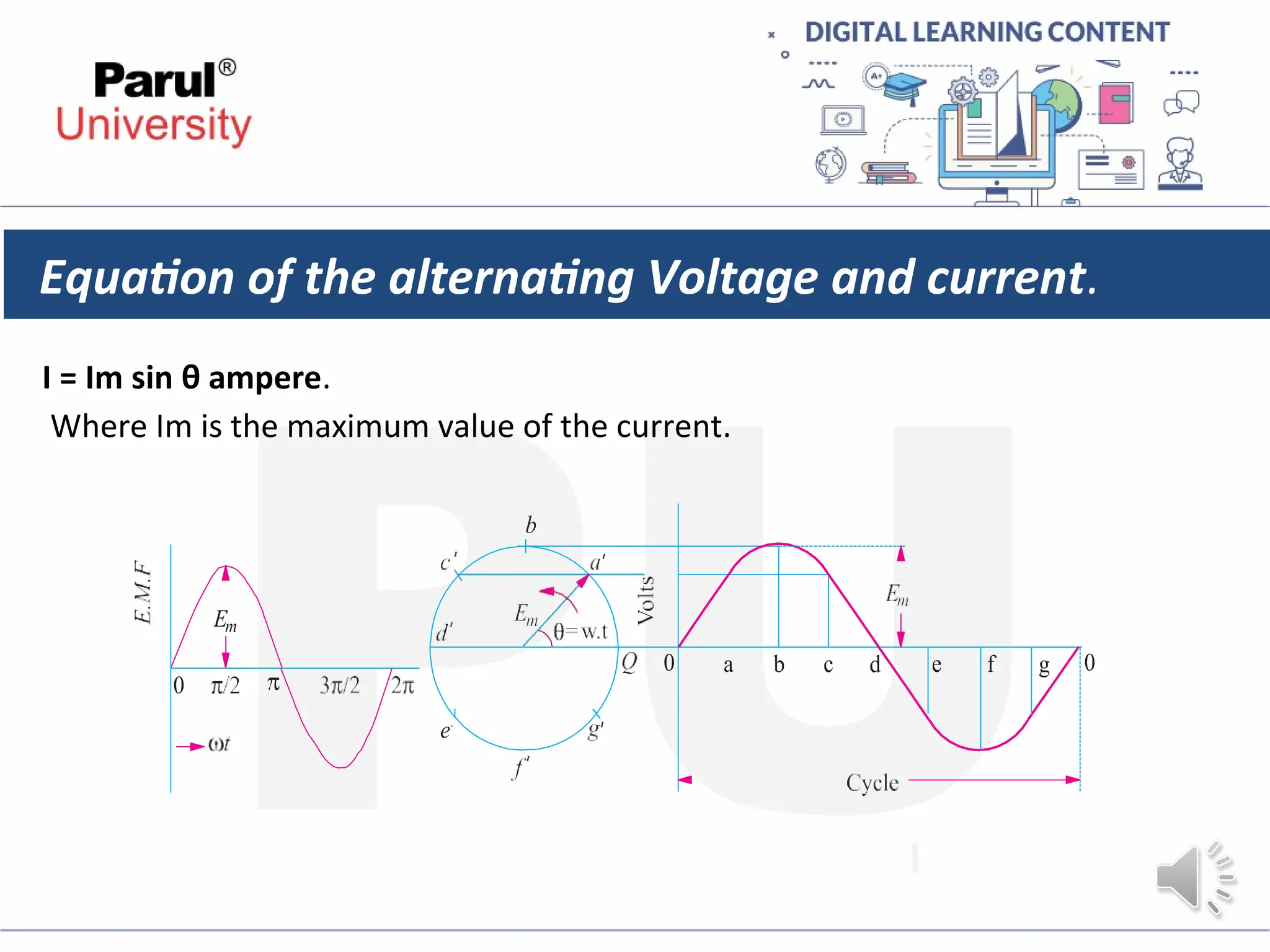
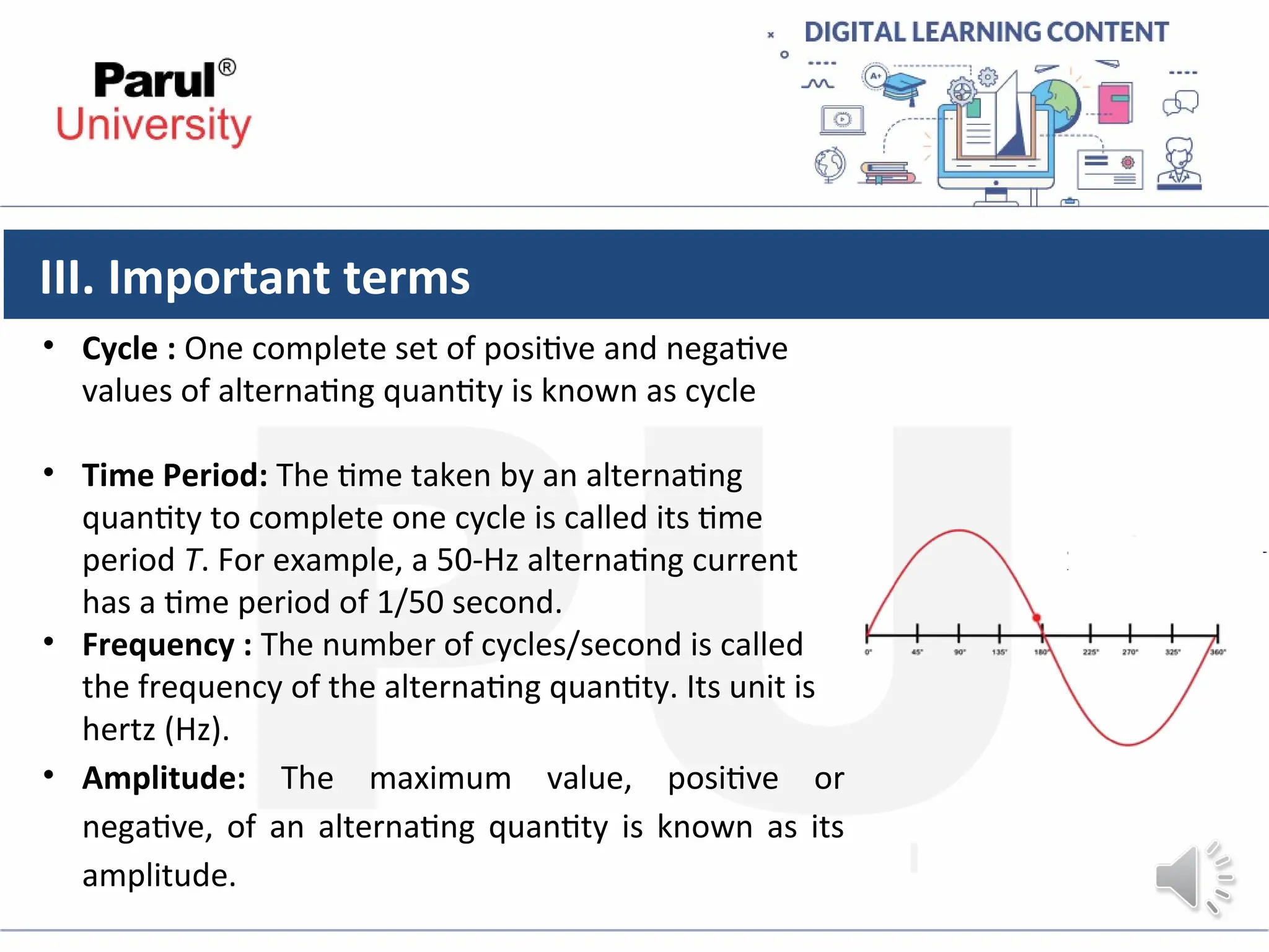
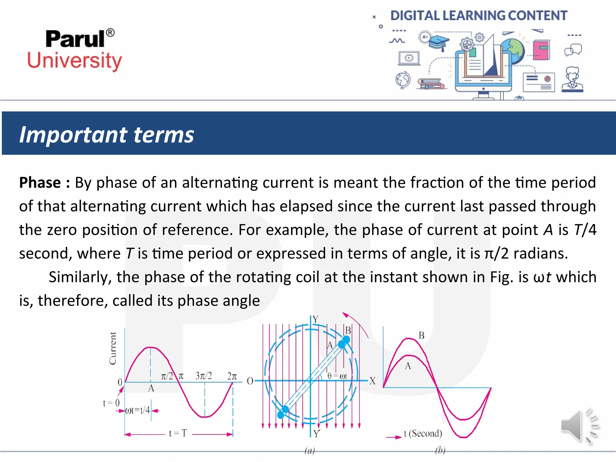
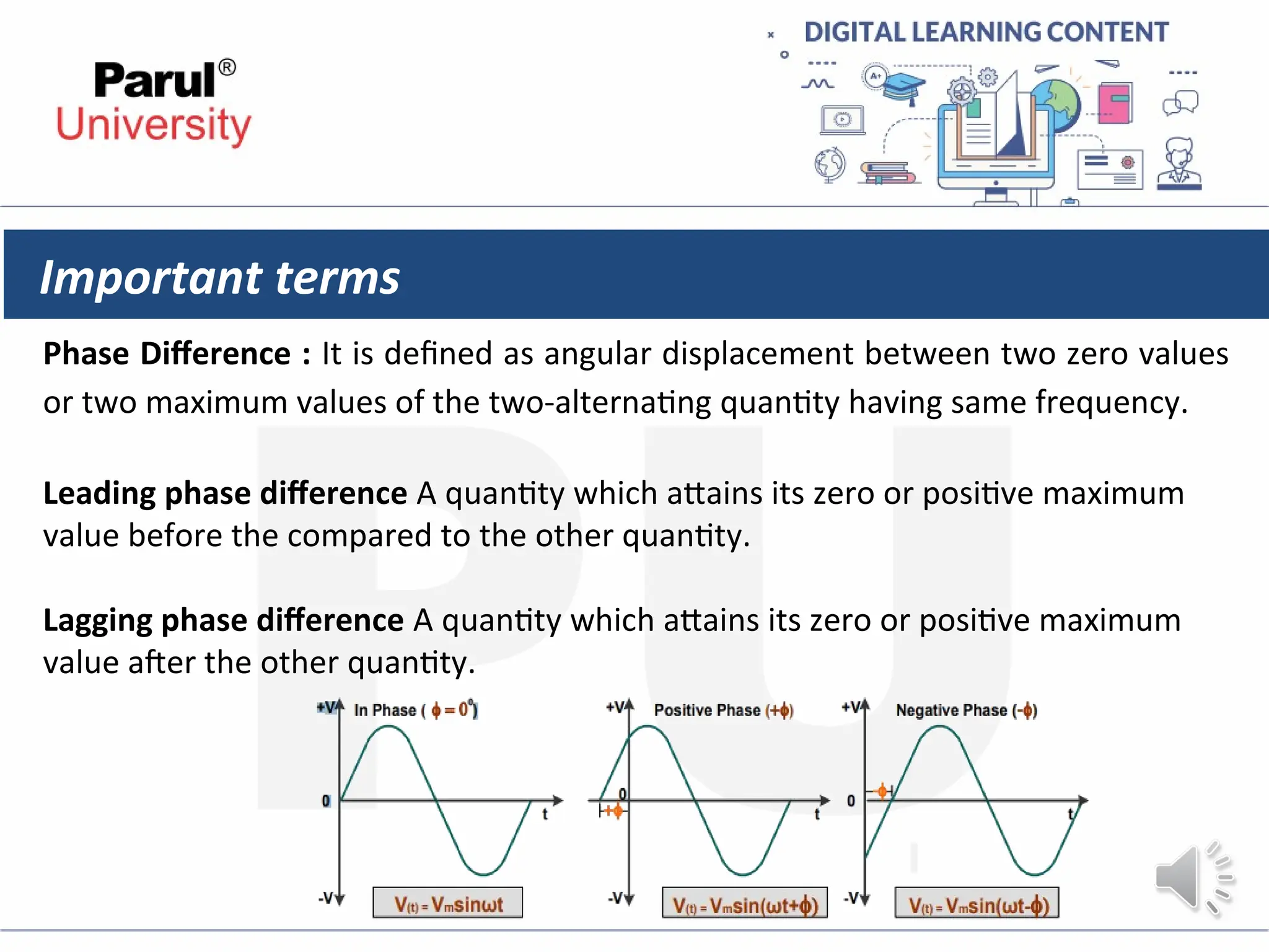
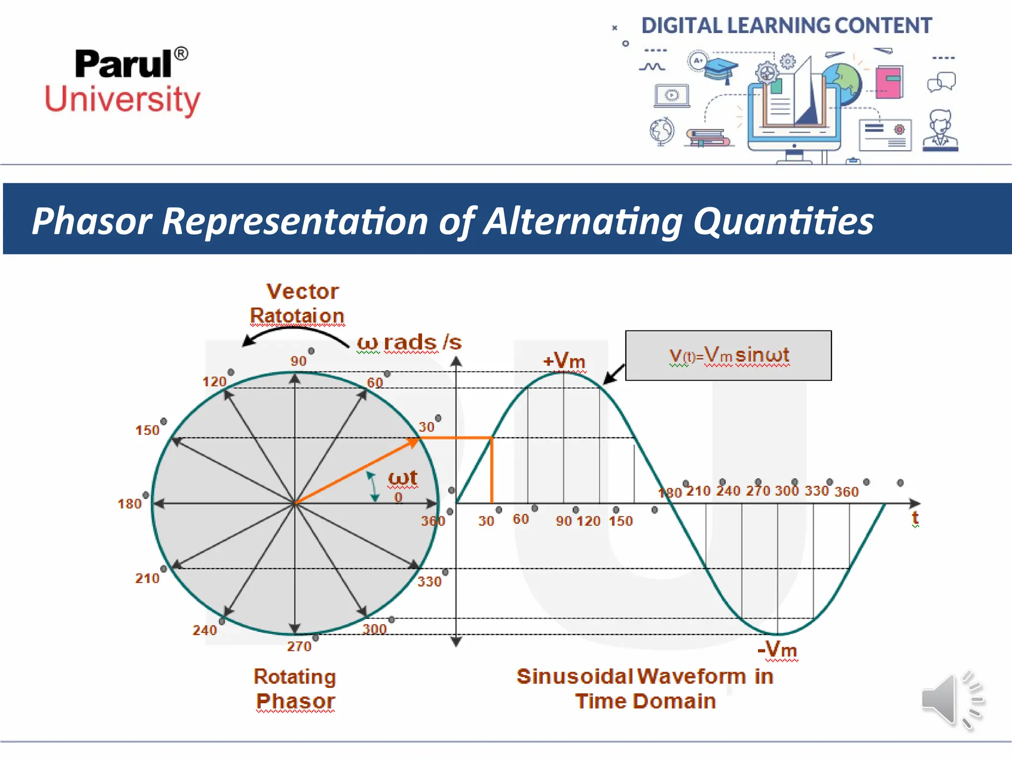
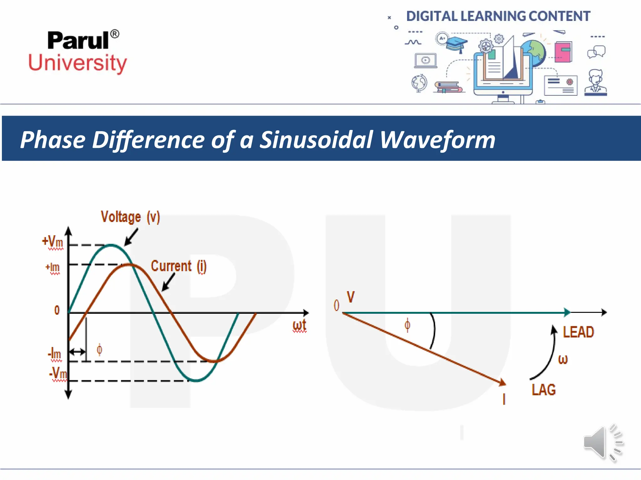
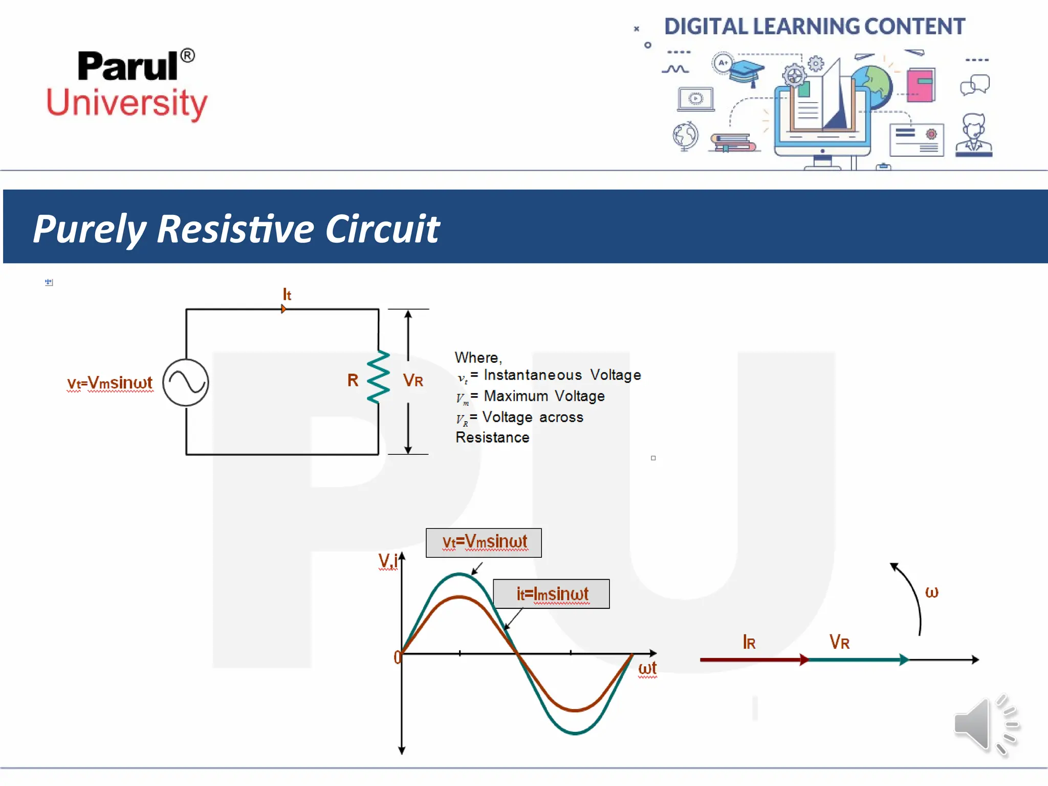
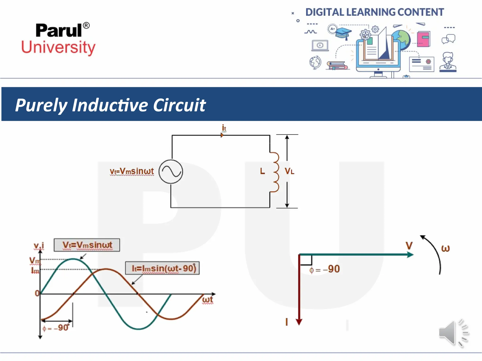
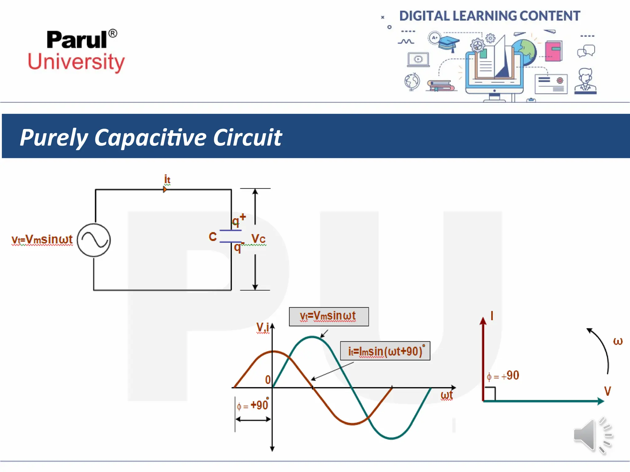
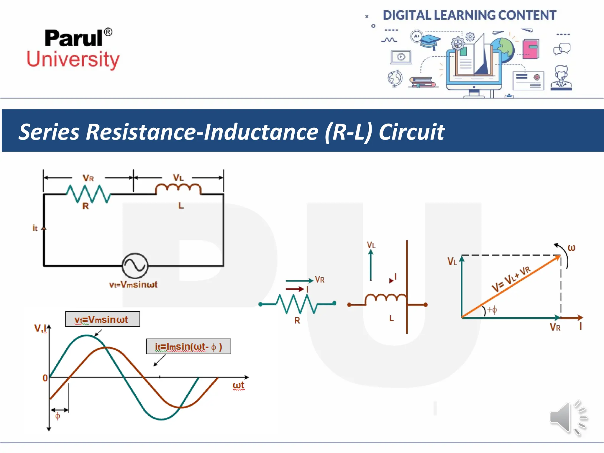
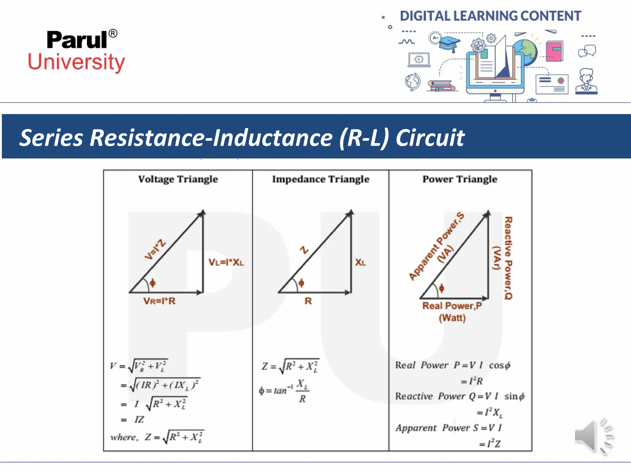
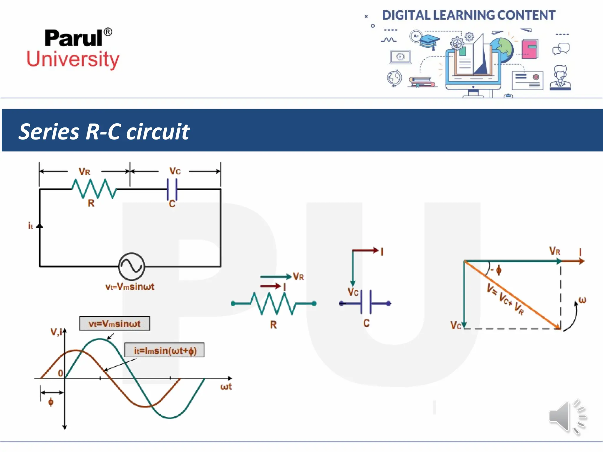
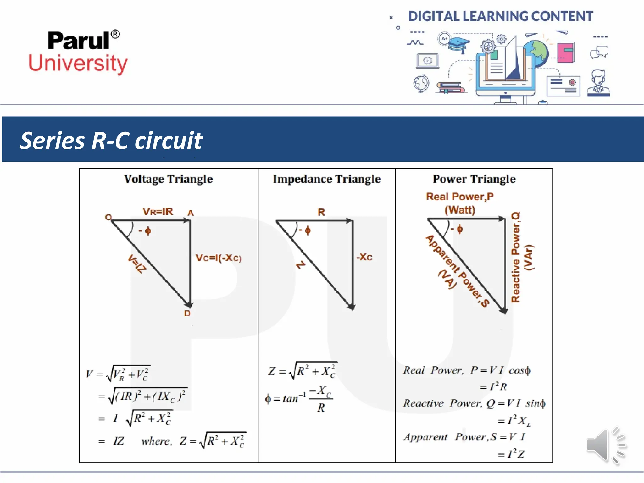
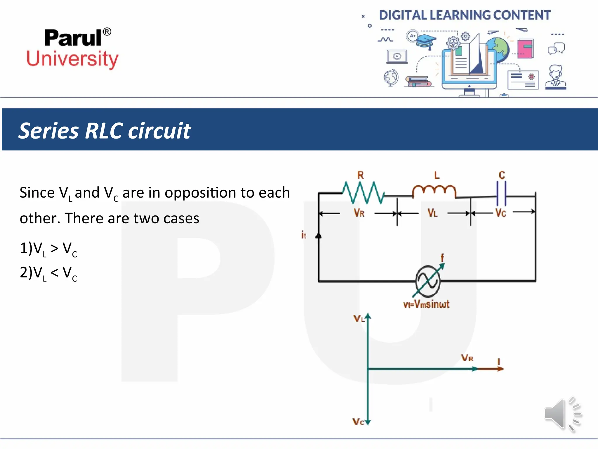
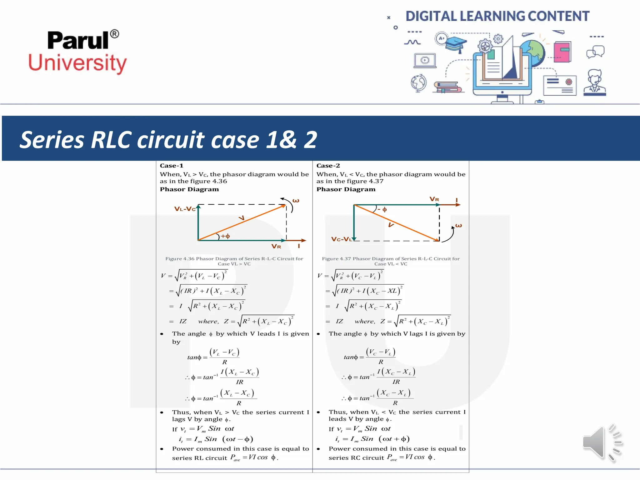
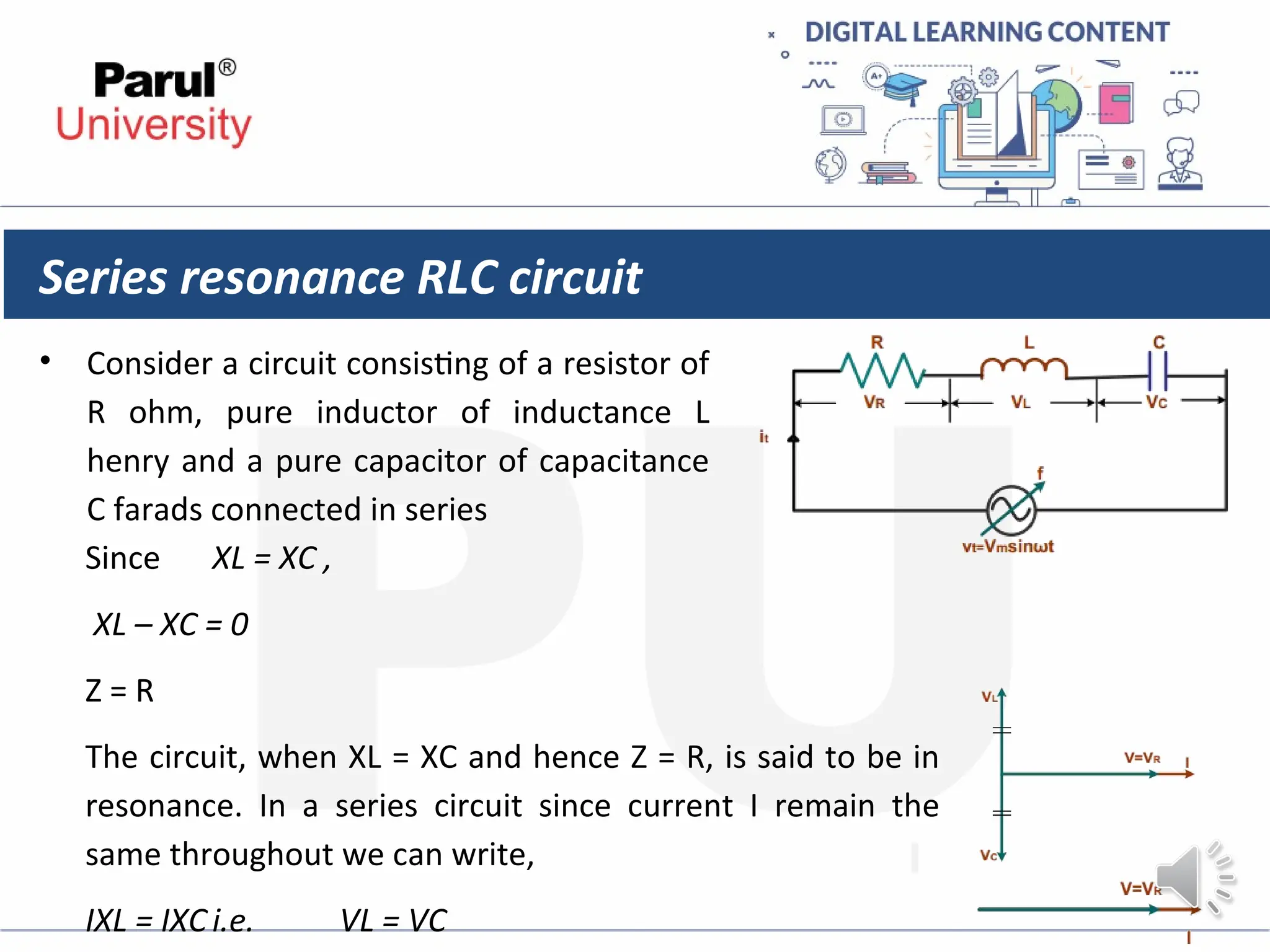
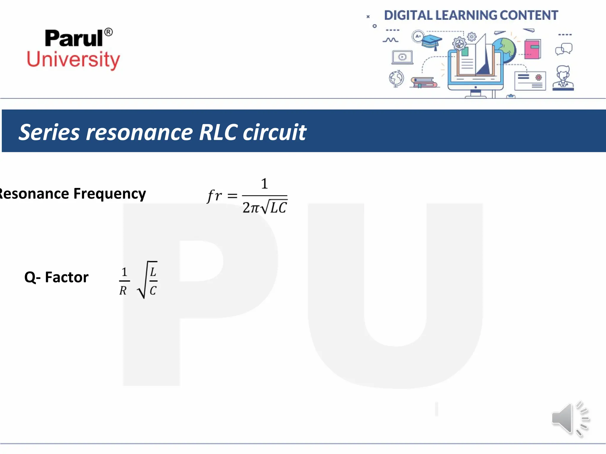
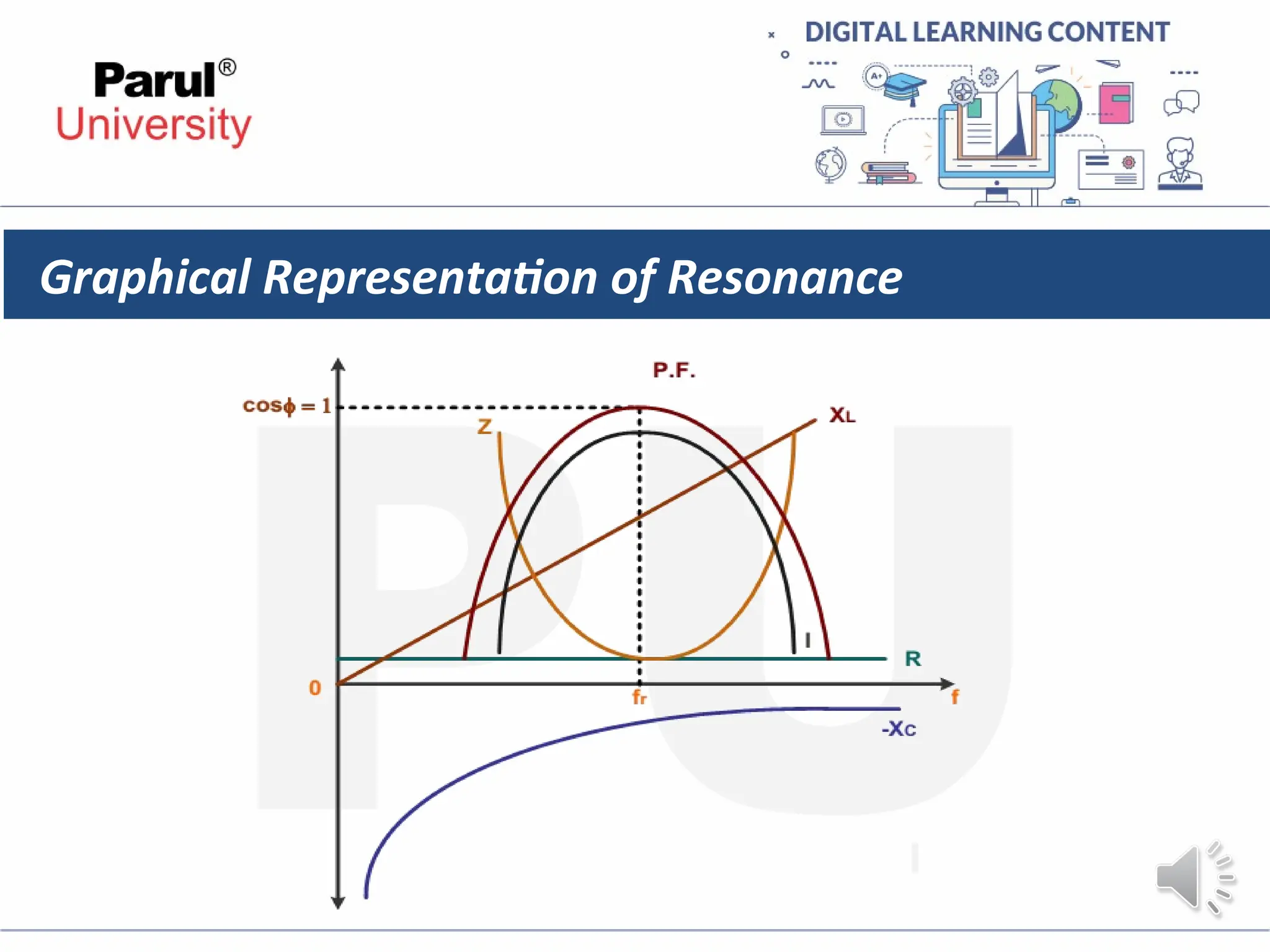
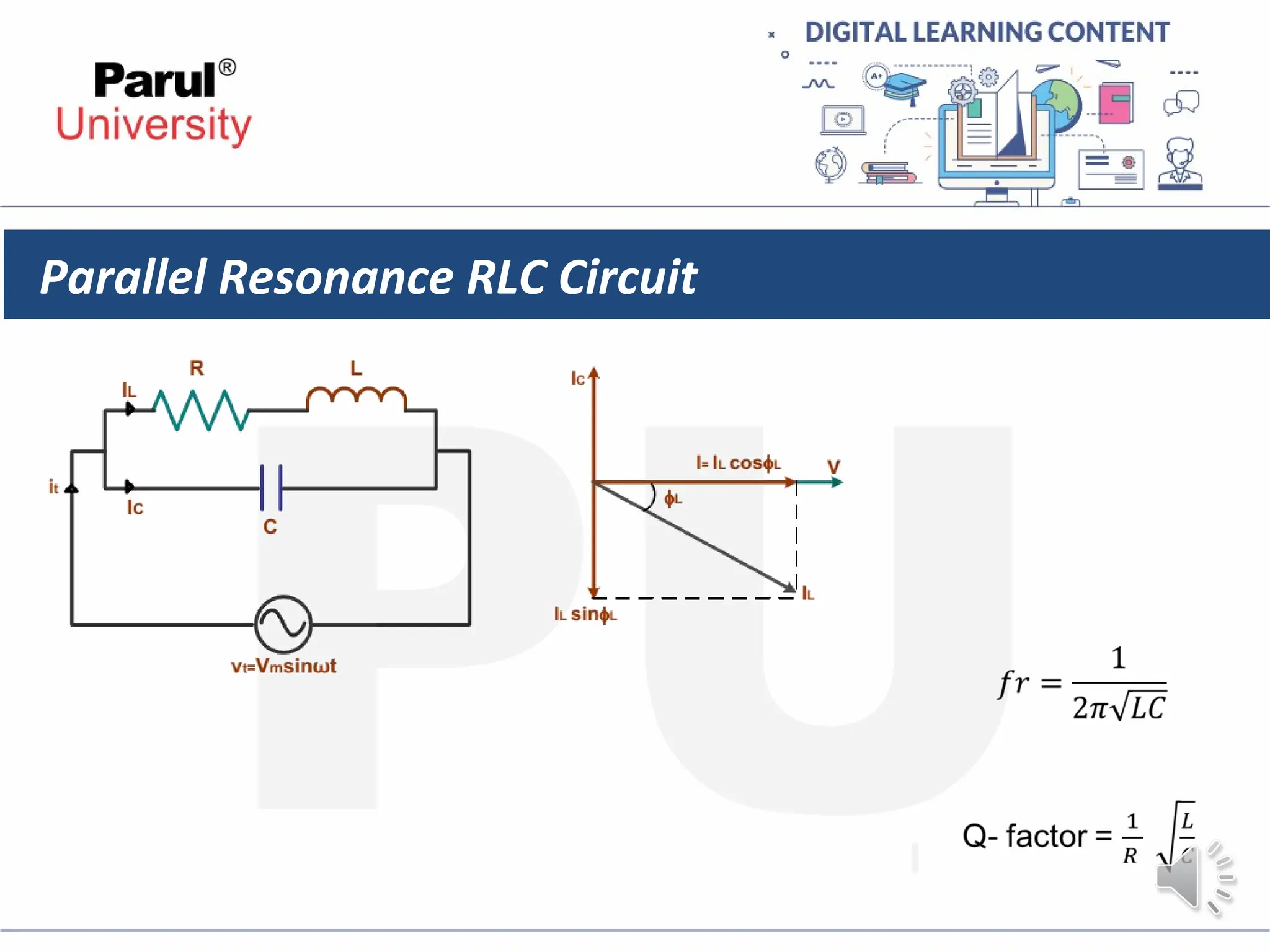
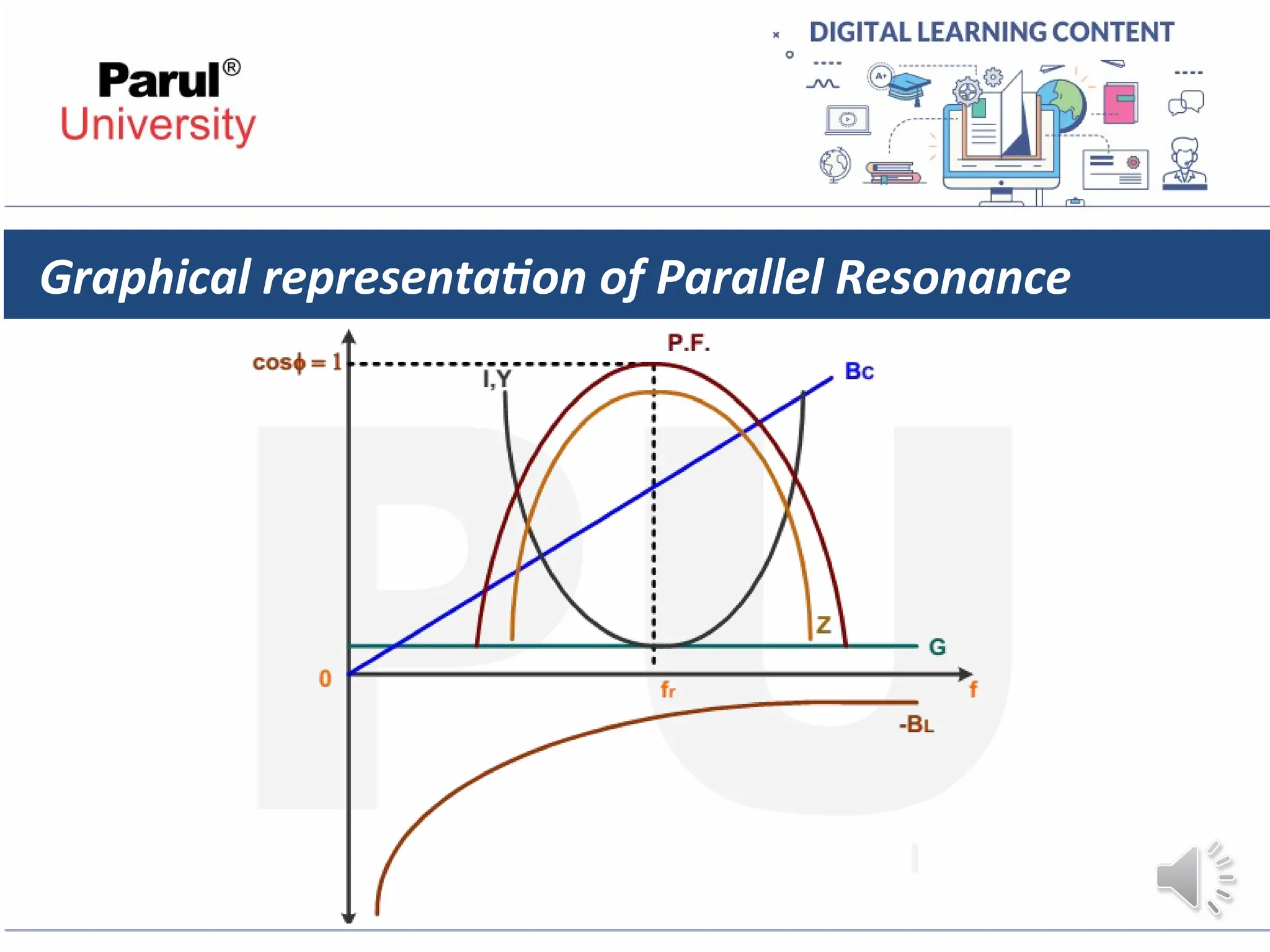
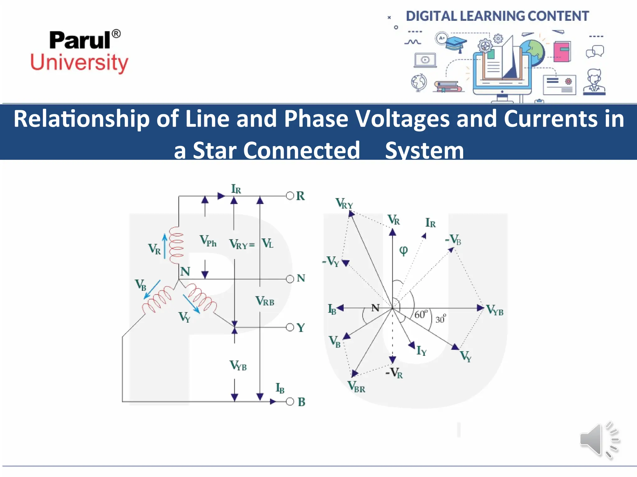
Electrical and Electronics Engineering-
303106103
Electrical Engineering
AC Circuit
CHAPTER-2
I. Introduction
• In an electric circuit , the direct current flows in a only one direction. If the
applied voltage and circuit resistance are kept constant the magnitude of the
current flowing through the circuit also remains constant.
• If the value of the current changes either due to a change in the applied
voltage or the circuit resistance, but continues to flow in the same direction, it
is then termed as a pulsating current. The alternating current is one witch
varies periodically in magnitude and direction over a definite cycle. Each cycle
of the alternating current consists of two half cycles. During one half cycle ,the
current varies in one direction and during the other half cycle, in the opposite
direction.
II. Generation of Alternating Voltages and Currents
• Alternating voltage may be generated by rotating a coil in a magnetic field, as
shown in Fig. (a) or by rotating a magnetic field within a stationary coil, as
shown in Fig. (b). The value of the voltage generated depends, in each case,
upon the number of turns in the coil, strength of the field and the speed at
which the coil or magnetic field rotates. Alternating voltage may be generated
in either of the two ways shown above, but rotating-field method is the one
which is mostly used in practice
Equation of the alternating Voltage and current.
I = Im sin θ ampere.
Where Im is the maximum value of the current.
III. Important terms
• Cycle : One complete set of positive and negative
values of alternating quantity is known as cycle
• Time Period: The time taken by an alternating
quantity to complete one cycle is called its time
period T. For example, a 50-Hz alternating current
has a time period of 1/50 second.
• Frequency : The number of cycles/second is called
the frequency of the alternating quantity. Its unit is
hertz (Hz).
• Amplitude: The maximum value, positive or
negative, of an alternating quantity is known as its
amplitude.
Important terms
Phase : By phase of an alternating current is meant the fraction of the time period
of that alternating current which has elapsed since the current last passed through
the zero position of reference. For example, the phase of current at point A is T/4
second, where T is time period or expressed in terms of angle, it is π/2 radians.
Similarly, the phase of the rotating coil at the instant shown in Fig. is ωt which
is, therefore, called its phase angle
Important terms
Phase Difference : It is defined as angular displacement between two zero values
or two maximum values of the two-alternating quantity having same frequency.
Leading phase difference A quantity which attains its zero or positive maximum
value before the compared to the other quantity.
Lagging phase difference A quantity which attains its zero or positive maximum
value after the other quantity.
Important terms
• Amplitude/ Peak value/ Crest value/ Maximum value
It is defined as the maximum value (either positive or negative) attained by an
alternating quantity in one cycle. Generally denoted by capital letters.
e.g. Im= Maximum Value of current
Vm= Maximum value of voltage
Pm= Maximum values of power
• Average value
It is defined as the average of all instantaneous value of alternating quantities over
a half cycle.
e.g. Vave = Average value of voltage
Iave = Average value of current
Important terms
• RMS value
It is the equivalent dc current which when flowing through a given circuit for a
given time produces same amount of heat as produced by an alternating
current when flowing through the same circuit for the same time.
e.g. Vrms =Root Mean Square value of voltage Irms = Root Mean Square value of
current
Power factor
It is defined as the cosine of angle between voltage and current. Power Factor
= pf = cosΦ, where Φ is the angle between voltage and current.
Important terms
Active power
It is the actual power consumed in any circuit. It is given by product of rms
voltage and rms current and cosine angle between voltage and current. (VI
cosΦ).
Active Power= P= I2
R = VI cosΦ. Unit is Watt (W) or kW.
Reactive power
The power drawn by the circuit due to reactive component of current is called as
reactive power. It is given by product of rms voltage and rms current and sine
angle between voltage and current (VI sinΦ).
Reactive Power = Q= I2
X = VIsinΦ.
Unit is VAR or kVAR.
Important terms
Apparent power
It is the product of rms value of voltage and rms value of current. It is total power
supplied to the circuit.
Apparent Power=S=VI. Unit is VA or kVA.
Peak factor/ Crest factor
It is defined as the ratio of peak value (crest value or maximum value) to rms
value of an alternating quantity. Peak factor = Kp = 1.414 for sine wave.
Phasor Representation of Alternating Quantities
Phase Difference of a Sinusoidal Waveform
Purely Resistive Circuit
Purely Inductive Circuit
Purely Capacitive Circuit
Series Resistance-Inductance (R-L) Circuit
Series R-C circuit
Series R-C circuit
Series RLC circuit
Since VL and VC are in opposition to each
other. There are two cases
1)VL > VC
2)VL < VC
Series RLC circuit case 1& 2
Series resonance RLC circuit
• Consider a circuit consisting of a resistor of
R ohm, pure inductor of inductance L
henry and a pure capacitor of capacitance
C farads connected in series
Since XL = XC ,
XL – XC = 0
Z = R
The circuit, when XL = XC and hence Z = R, is said to be in
resonance. In a series circuit since current I remain the
same throughout we can write,
IXL = IXC i.e. VL = VC
Series resonance RLC circuit
Resonance Frequency
Q- Factor
Graphical Representation of Resonance
Parallel Resonance RLC Circuit
Graphical representation of Parallel Resonance
Relationship of Line and Phase Voltages and Currents in
a Star Connected System
Relationship of Line and Phase Voltages and Currents in
a Star Connected System
We know in the star connection, line current is same as phase current. The
magnitude of this current is same in all three phases and say it is IL.
∴ IR = IY = IB = IL,
Where, IR is line current of R phase, IY is line current of Y phase and IB is
line current of B phase. Again, phase current, Iph of each phase is same as
line current IL in star connected system.
∴ IR = IY = IB = IL = Iph.
Relationship of Line and Phase Voltages and Currents in
a Star Connected System
The voltage across Y and B terminal of the star connected circuit is VYBBR.
From the diagram, it is found that
VRY = VR + (− VY)
Similarly, VYB = VY + (− VB)
And, VBR = VB + (− VR)
Now, as angle between VR and VY is 120o(electrical), the angle between VR
and – VY is 180o – 120o = 60o(electrical).
Relationship of Line and Phase Voltages and Currents in
a Star Connected System
Thus, for the star-connected system line voltage = √3 × phase voltage.
and Line current = Phase current
REFERENCES
1) https://www.electronics-tutorials.ws/dccircuits/current-source.html
2) https://onlineaavedan.com/study_material/1546513067.pdf
3) Basis of electrical and electronics by B.L. Theraja volume1
www.paruluniversity.ac.in

Ch.2 A.C Circuit.ppt for electrical engineering

  • 1.
    Electrical and ElectronicsEngineering- 303106103 Electrical Engineering
  • 2.
  • 3.
    I. Introduction • Inan electric circuit , the direct current flows in a only one direction. If the applied voltage and circuit resistance are kept constant the magnitude of the current flowing through the circuit also remains constant. • If the value of the current changes either due to a change in the applied voltage or the circuit resistance, but continues to flow in the same direction, it is then termed as a pulsating current. The alternating current is one witch varies periodically in magnitude and direction over a definite cycle. Each cycle of the alternating current consists of two half cycles. During one half cycle ,the current varies in one direction and during the other half cycle, in the opposite direction.
  • 4.
    II. Generation ofAlternating Voltages and Currents • Alternating voltage may be generated by rotating a coil in a magnetic field, as shown in Fig. (a) or by rotating a magnetic field within a stationary coil, as shown in Fig. (b). The value of the voltage generated depends, in each case, upon the number of turns in the coil, strength of the field and the speed at which the coil or magnetic field rotates. Alternating voltage may be generated in either of the two ways shown above, but rotating-field method is the one which is mostly used in practice
  • 5.
    Equation of thealternating Voltage and current.
  • 6.
    Equation of thealternating Voltage and current. I = Im sin θ ampere. Where Im is the maximum value of the current.
  • 7.
    III. Important terms •Cycle : One complete set of positive and negative values of alternating quantity is known as cycle • Time Period: The time taken by an alternating quantity to complete one cycle is called its time period T. For example, a 50-Hz alternating current has a time period of 1/50 second. • Frequency : The number of cycles/second is called the frequency of the alternating quantity. Its unit is hertz (Hz). • Amplitude: The maximum value, positive or negative, of an alternating quantity is known as its amplitude.
  • 8.
    Important terms Phase :By phase of an alternating current is meant the fraction of the time period of that alternating current which has elapsed since the current last passed through the zero position of reference. For example, the phase of current at point A is T/4 second, where T is time period or expressed in terms of angle, it is π/2 radians. Similarly, the phase of the rotating coil at the instant shown in Fig. is ωt which is, therefore, called its phase angle
  • 9.
    Important terms Phase Difference: It is defined as angular displacement between two zero values or two maximum values of the two-alternating quantity having same frequency. Leading phase difference A quantity which attains its zero or positive maximum value before the compared to the other quantity. Lagging phase difference A quantity which attains its zero or positive maximum value after the other quantity.
  • 10.
    Important terms • Amplitude/Peak value/ Crest value/ Maximum value It is defined as the maximum value (either positive or negative) attained by an alternating quantity in one cycle. Generally denoted by capital letters. e.g. Im= Maximum Value of current Vm= Maximum value of voltage Pm= Maximum values of power • Average value It is defined as the average of all instantaneous value of alternating quantities over a half cycle. e.g. Vave = Average value of voltage Iave = Average value of current
  • 11.
    Important terms • RMSvalue It is the equivalent dc current which when flowing through a given circuit for a given time produces same amount of heat as produced by an alternating current when flowing through the same circuit for the same time. e.g. Vrms =Root Mean Square value of voltage Irms = Root Mean Square value of current Power factor It is defined as the cosine of angle between voltage and current. Power Factor = pf = cosΦ, where Φ is the angle between voltage and current.
  • 12.
    Important terms Active power Itis the actual power consumed in any circuit. It is given by product of rms voltage and rms current and cosine angle between voltage and current. (VI cosΦ). Active Power= P= I2 R = VI cosΦ. Unit is Watt (W) or kW. Reactive power The power drawn by the circuit due to reactive component of current is called as reactive power. It is given by product of rms voltage and rms current and sine angle between voltage and current (VI sinΦ). Reactive Power = Q= I2 X = VIsinΦ. Unit is VAR or kVAR.
  • 13.
    Important terms Apparent power Itis the product of rms value of voltage and rms value of current. It is total power supplied to the circuit. Apparent Power=S=VI. Unit is VA or kVA. Peak factor/ Crest factor It is defined as the ratio of peak value (crest value or maximum value) to rms value of an alternating quantity. Peak factor = Kp = 1.414 for sine wave.
  • 14.
    Phasor Representation ofAlternating Quantities
  • 15.
    Phase Difference ofa Sinusoidal Waveform
  • 16.
  • 17.
  • 18.
  • 19.
  • 20.
  • 21.
  • 22.
  • 23.
    Series RLC circuit SinceVL and VC are in opposition to each other. There are two cases 1)VL > VC 2)VL < VC
  • 24.
  • 25.
    Series resonance RLCcircuit • Consider a circuit consisting of a resistor of R ohm, pure inductor of inductance L henry and a pure capacitor of capacitance C farads connected in series Since XL = XC , XL – XC = 0 Z = R The circuit, when XL = XC and hence Z = R, is said to be in resonance. In a series circuit since current I remain the same throughout we can write, IXL = IXC i.e. VL = VC
  • 26.
    Series resonance RLCcircuit Resonance Frequency Q- Factor
  • 27.
  • 28.
  • 29.
    Graphical representation ofParallel Resonance
  • 30.
    Relationship of Lineand Phase Voltages and Currents in a Star Connected System
  • 31.
    Relationship of Lineand Phase Voltages and Currents in a Star Connected System We know in the star connection, line current is same as phase current. The magnitude of this current is same in all three phases and say it is IL. ∴ IR = IY = IB = IL, Where, IR is line current of R phase, IY is line current of Y phase and IB is line current of B phase. Again, phase current, Iph of each phase is same as line current IL in star connected system. ∴ IR = IY = IB = IL = Iph.
  • 32.
    Relationship of Lineand Phase Voltages and Currents in a Star Connected System The voltage across Y and B terminal of the star connected circuit is VYBBR. From the diagram, it is found that VRY = VR + (− VY) Similarly, VYB = VY + (− VB) And, VBR = VB + (− VR) Now, as angle between VR and VY is 120o(electrical), the angle between VR and – VY is 180o – 120o = 60o(electrical).
  • 33.
    Relationship of Lineand Phase Voltages and Currents in a Star Connected System Thus, for the star-connected system line voltage = √3 × phase voltage. and Line current = Phase current
  • 34.
  • 35.