Creating a PowerPoint presentation on **Alternating Current (AC) Wave Propagation** involves breaking down the topic into clear, concise slides with visuals and explanations. Below is an outline for your presentation, including key points and slide content suggestions.
---
### **Slide 1: Title Slide**
- **Title**: Alternating Current (AC) Wave Propagation
- **Subtitle**: Understanding the Principles and Applications of AC Waves
- **Your Name**
- **Date**
---
### **Slide 2: Introduction to Alternating Current (AC)**
- **Definition**: Alternating Current (AC) is an electric current that periodically reverses direction.
- **Key Characteristics**:
- Voltage and current vary sinusoidally with time.
- Frequency (Hz) determines the number of cycles per second.
- Common frequencies: 50 Hz (Europe, Asia) and 60 Hz (North America).
- **Applications**: Power transmission, household appliances, industrial machinery.
---
### **Slide 3: AC vs. Direct Current (DC)**
- **AC**:
- Reverses direction periodically.
- Easier to transform voltage levels.
- Used for long-distance power transmission.
- **DC**:
- Flows in one direction.
- Used in batteries, electronics, and low-voltage applications.
- **Visual**: Sine wave (AC) vs. straight line (DC).
---
### **Slide 4: AC Waveform**
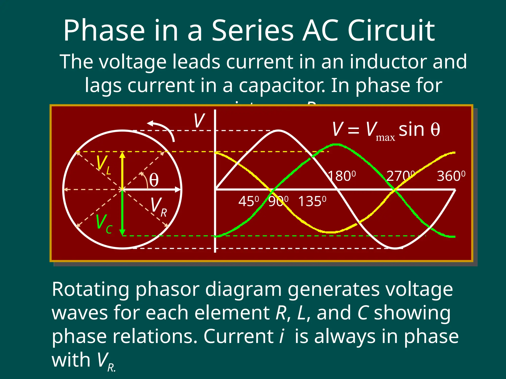
- **Waveform Representation**:
- Sinusoidal waveform: \( V(t) = V_{\text{max}} \sin(2\pi ft + \phi) \)
- \( V_{\text{max}} \): Peak voltage.
- \( f \): Frequency.
- \( \phi \): Phase angle.
- **Key Parameters**:
- **Amplitude**: Maximum value of the wave.
- **Frequency**: Number of cycles per second.
- **Period**: Time for one complete cycle (\( T = 1/f \)).
- **Phase**: Shift in the waveform relative to a reference.
---
### **Slide 5: AC Wave Propagation**
- **Definition**: The movement of AC waves through a medium (e.g., wires, air, or space).
- **Key Concepts**:
- **Electromagnetic Waves**: AC waves propagate as electromagnetic waves.
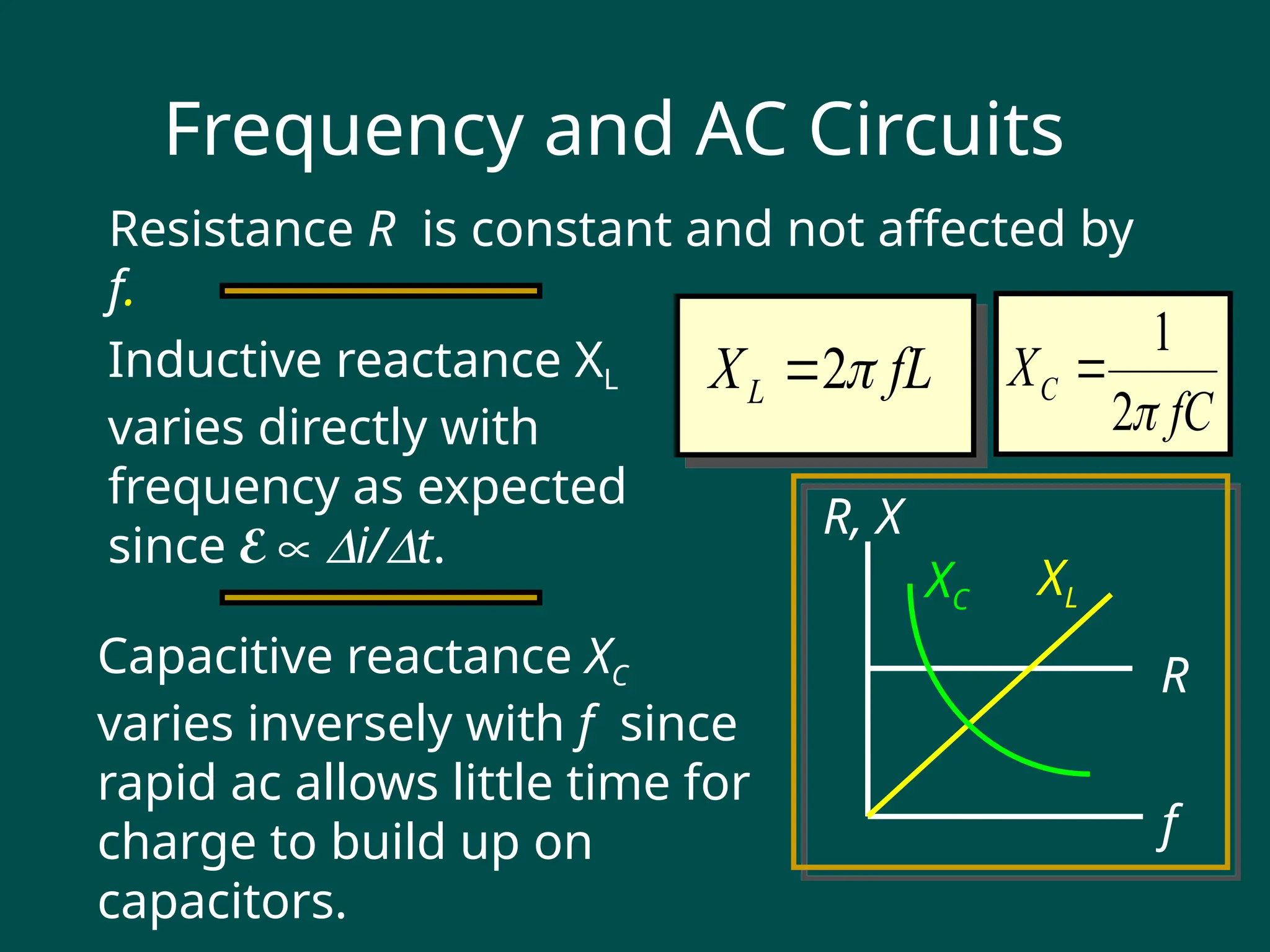
- **Wave Velocity**: Speed at which the wave travels (\( v = f \lambda \), where \( \lambda \) is the wavelength).
- **Impedance**: Opposition to AC wave propagation (depends on resistance, inductance, and capacitance).
- **Visual**: Diagram of AC wave propagation in a transmission line.
---
### **Slide 6: AC in Transmission Lines**
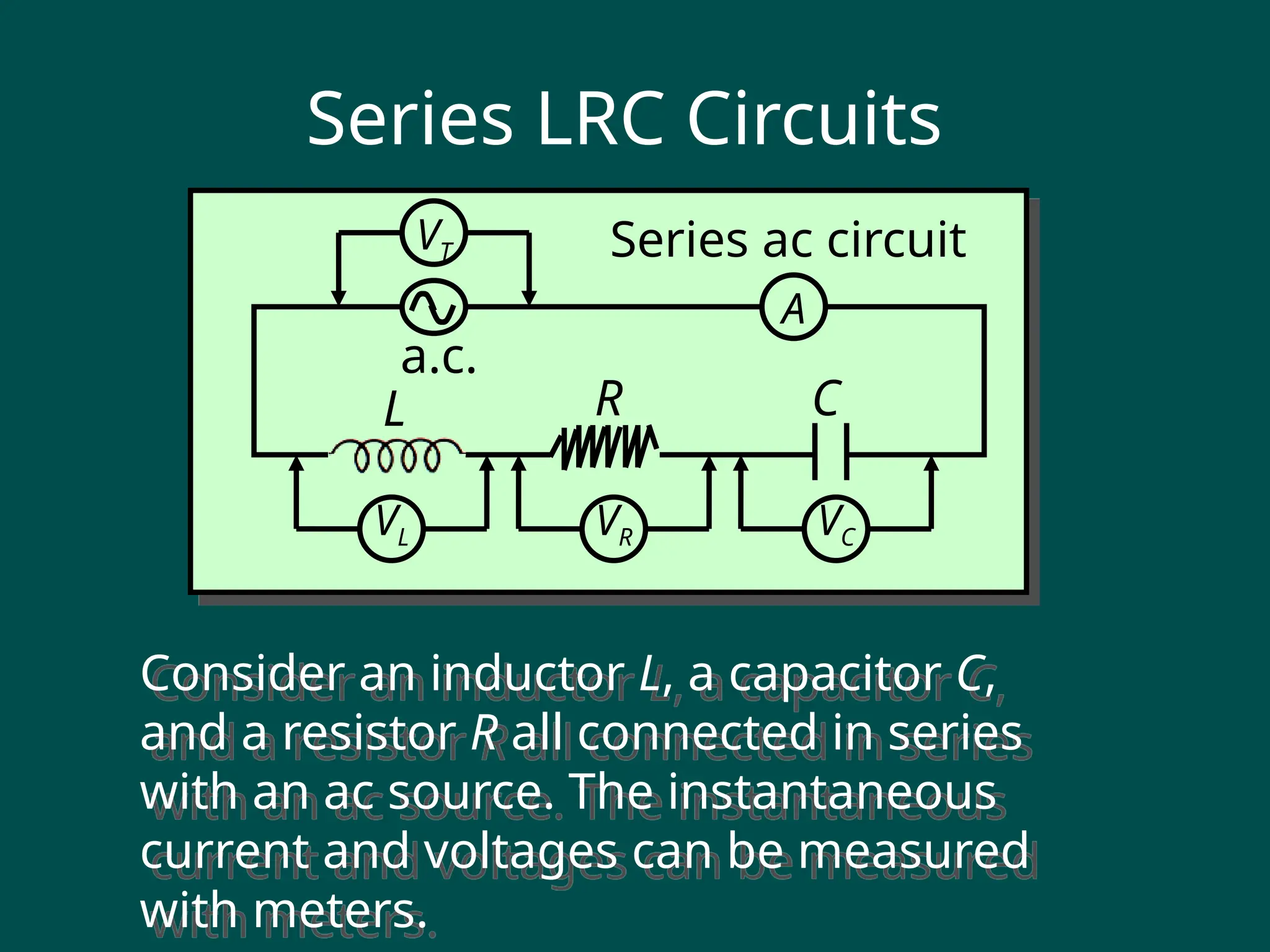
- **Transmission Lines**:
- Used to transfer AC power from generators to consumers.
- Examples: Overhead power lines, underground cables.
- **Challenges**:
- **Attenuation**: Loss of signal strength over distance.
- **Reflection**: Mismatch in impedance causes signal reflection.
- **Distortion**: Alteration of the waveform due to inductance and capacitance.
- **Visual**: Diagram of a transmission line with labeled components.
---
### **Slide 7: AC Wave Propagation in Free Space**
- **Electromagnetic Radiation**:
- AC waves can propagate through free space as electromagnetic waves.
- Examples: Radio waves, microwaves, and light waves.
-