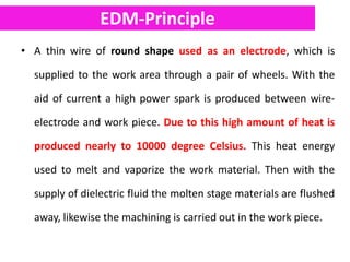
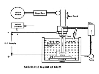
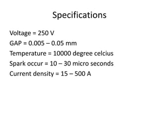
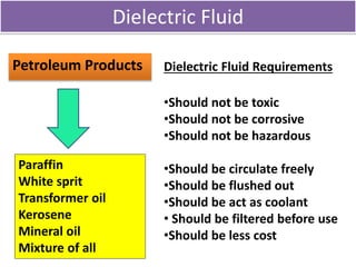
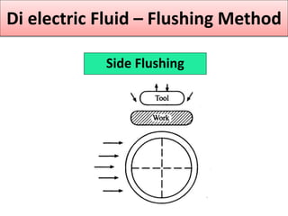
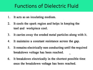
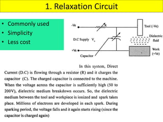
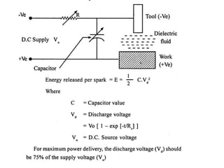
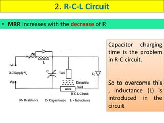
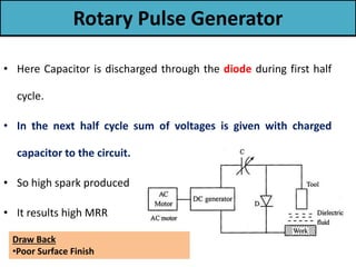
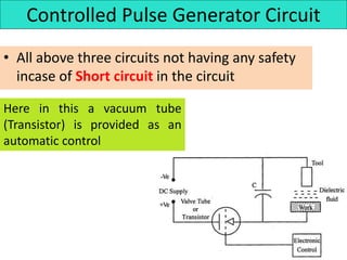
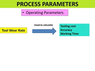
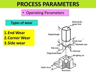
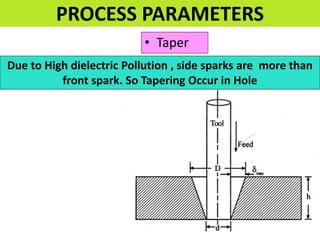
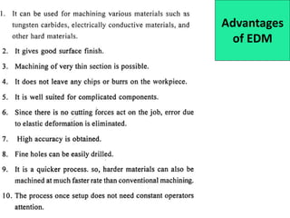
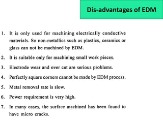
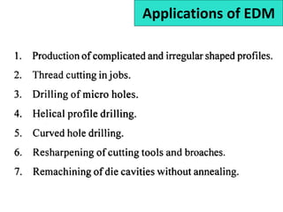
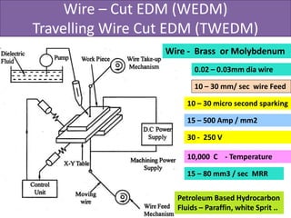
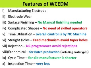
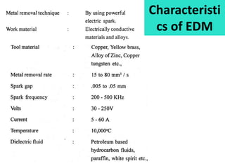
ELECTRICAL ENERGY BASED
PROCESSES
EDM-Principle
• A thin wire of round shape used as an electrode, which is
supplied to the work area through a pair of wheels. With the
aid of current a high power spark is produced between wire-
electrode and work piece. Due to this high amount of heat is
produced nearly to 10000 degree Celsius. This heat energy
used to melt and vaporize the work material. Then with the
supply of dielectric fluid the molten stage materials are flushed
away, likewise the machining is carried out in the work piece.
.
Specifications
Voltage = 250 V
GAP = 0.005 – 0.05 mm
Temperature = 10000 degree celcius
Spark occur = 10 – 30 micro seconds
Current density = 15 – 500 A
Dielectric Fluid
Petroleum Products
Paraffin
White sprit
Transformer oil
Kerosene
Mineral oil
Mixture of all
Dielectric Fluid Requirements
•Should not be toxic
•Should not be corrosive
•Should not be hazardous
•Should be circulate freely
•Should be flushed out
•Should be act as coolant
• Should be filtered before use
•Should be less cost
Di electric Fluid – Flushing Method
1. Pressure Flushing
2. Suction Flushing
3. Side Flushing
Pressure Flushing
Di electric Fluid – Flushing Method
Suction Flushing
Di electric Fluid – Flushing Method
Side Flushing
Di electric Fluid – Flushing Method
Functions of Dielectric Fluid
Electrode (Tool)
• Graphite ( Non Metallic)
• Copper (Metallic)
• Copper - Tungsten
POWER GENERATING CIRCUITS
SPARK GENERATING CIRCUITS
OR
AC Current DC Current
Rectifier is used to convert AC to DC
Types
1. Relaxation Circuit
• Commonly used
• Simplicity
• Less cost
Dis-advantages
2. R-C-L Circuit
• MRR increases with the decrease of R
Capacitor charging
time is the problem
in R-C circuit.
So to overcome this
, inductance (L) is
introduced in the
circuit
Rotary Pulse Generator
• R-C and R-C-L yield low MRR
• Rotary Pulse Generator over come Drawback
of above to circuits
• It give high MRR
• It give good Surface finish
• It give low tool wear
• It provide better control in all Parameters
Rotary Pulse Generator
• Here Capacitor is discharged through the diode during first half
cycle.
• In the next half cycle sum of voltages is given with charged
capacitor to the circuit.
• So high spark produced
• It results high MRR
Draw Back
•Poor Surface Finish
Controlled Pulse Generator Circuit
• All above three circuits not having any safety
incase of Short circuit in the circuit
Here in this a vacuum tube
(Transistor) is provided as an
automatic control
PROCESS PARAMETERS
.
EDM
1. Operating Parameters
2. Taper
3. Surface finish
4. Current Density
PROCESS PARAMETERS
• Operating Parameters
PROCESS PARAMETERS
Tool Wear Rate
Tooling cost
Accuracy
Working Time
Used to calculate
• Operating Parameters
PROCESS PARAMETERS
Types of wear
1.End Wear
2.Corner Wear
3.Side wear
• Taper
PROCESS PARAMETERS
Due to High dielectric Pollution , side sparks are more than
front spark. So Tapering Occur in Hole
• Surface Finish
PROCESS PARAMETERS
It Depend on
i) Energy of Pulse
ii) Frequency of operation
• Current Density
PROCESS PARAMETERS
Current
Density
(More
Spark)
= MRR + Surface
Roughness
Current
Density
(Less
Spark)
= MRR + Surface
Roughness
Good Surface Finish
Poor Surface Finish
Advantages
of EDM
Dis-advantages of EDM
Applications of EDM
Wire – Cut EDM (WEDM)
Travelling Wire Cut EDM (TWEDM)
0.02 – 0.03mm dia wire
Wire - Brass or Molybdenum
10 – 30 micro second sparking
15 – 500 Amp / mm2
30 - 250 V
10,000 C - Temperature
10 – 30 mm/ sec wire Feed
15 – 80 mm3 / sec MRR
Petroleum Based Hydrocarbon
Fluids – Paraffin, white Sprit ..
Features of WCEDM
i) Manufacturing Electrode
ii) Electrode Wear
iii) Surface Finishing – No Manual finishing needed
iv) Complicated Shapes – No need of skilled operators
v) Time Utilization – overall control is by NC Machine
vi) Straight Holes – Feed mechanism avoid taper holes
vii) Rejection – NC programmes avoid rejections
viii)Economical – for Batch production (including prototypes)
ix) Cycle Time – for die manufacturer is shorter
x) Inspection Time – very less
Disadvantages of WEDM
• High Capital cost
• Cutting Rate is slow
• Not suitable for large work pieces
Applications of WEDM
• In the manufacturing of
Gears
Tools
Rotors
Turbine Blades
Cams
Wire Cut EDM Vs EDM
Characteristi
cs of EDM

EDM and Wire Cut EDM

  • 1.
  • 2.
    EDM-Principle • A thinwire of round shape used as an electrode, which is supplied to the work area through a pair of wheels. With the aid of current a high power spark is produced between wire- electrode and work piece. Due to this high amount of heat is produced nearly to 10000 degree Celsius. This heat energy used to melt and vaporize the work material. Then with the supply of dielectric fluid the molten stage materials are flushed away, likewise the machining is carried out in the work piece.
  • 3.
  • 4.
    Specifications Voltage = 250V GAP = 0.005 – 0.05 mm Temperature = 10000 degree celcius Spark occur = 10 – 30 micro seconds Current density = 15 – 500 A
  • 5.
    Dielectric Fluid Petroleum Products Paraffin Whitesprit Transformer oil Kerosene Mineral oil Mixture of all Dielectric Fluid Requirements •Should not be toxic •Should not be corrosive •Should not be hazardous •Should be circulate freely •Should be flushed out •Should be act as coolant • Should be filtered before use •Should be less cost
  • 6.
    Di electric Fluid– Flushing Method 1. Pressure Flushing 2. Suction Flushing 3. Side Flushing
  • 7.
    Pressure Flushing Di electricFluid – Flushing Method
  • 8.
    Suction Flushing Di electricFluid – Flushing Method
  • 9.
    Side Flushing Di electricFluid – Flushing Method
  • 10.
  • 11.
    Electrode (Tool) • Graphite( Non Metallic) • Copper (Metallic) • Copper - Tungsten
  • 12.
    POWER GENERATING CIRCUITS SPARKGENERATING CIRCUITS OR AC Current DC Current Rectifier is used to convert AC to DC
  • 13.
  • 14.
    1. Relaxation Circuit •Commonly used • Simplicity • Less cost
  • 16.
  • 17.
    2. R-C-L Circuit •MRR increases with the decrease of R Capacitor charging time is the problem in R-C circuit. So to overcome this , inductance (L) is introduced in the circuit
  • 18.
    Rotary Pulse Generator •R-C and R-C-L yield low MRR • Rotary Pulse Generator over come Drawback of above to circuits • It give high MRR • It give good Surface finish • It give low tool wear • It provide better control in all Parameters
  • 19.
    Rotary Pulse Generator •Here Capacitor is discharged through the diode during first half cycle. • In the next half cycle sum of voltages is given with charged capacitor to the circuit. • So high spark produced • It results high MRR Draw Back •Poor Surface Finish
  • 20.
    Controlled Pulse GeneratorCircuit • All above three circuits not having any safety incase of Short circuit in the circuit Here in this a vacuum tube (Transistor) is provided as an automatic control
  • 21.
  • 22.
    1. Operating Parameters 2.Taper 3. Surface finish 4. Current Density PROCESS PARAMETERS
  • 23.
    • Operating Parameters PROCESSPARAMETERS Tool Wear Rate Tooling cost Accuracy Working Time Used to calculate
  • 24.
    • Operating Parameters PROCESSPARAMETERS Types of wear 1.End Wear 2.Corner Wear 3.Side wear
  • 25.
    • Taper PROCESS PARAMETERS Dueto High dielectric Pollution , side sparks are more than front spark. So Tapering Occur in Hole
  • 26.
    • Surface Finish PROCESSPARAMETERS It Depend on i) Energy of Pulse ii) Frequency of operation
  • 27.
    • Current Density PROCESSPARAMETERS Current Density (More Spark) = MRR + Surface Roughness Current Density (Less Spark) = MRR + Surface Roughness Good Surface Finish Poor Surface Finish
  • 28.
  • 29.
  • 30.
  • 31.
    Wire – CutEDM (WEDM) Travelling Wire Cut EDM (TWEDM) 0.02 – 0.03mm dia wire Wire - Brass or Molybdenum 10 – 30 micro second sparking 15 – 500 Amp / mm2 30 - 250 V 10,000 C - Temperature 10 – 30 mm/ sec wire Feed 15 – 80 mm3 / sec MRR Petroleum Based Hydrocarbon Fluids – Paraffin, white Sprit ..
  • 32.
    Features of WCEDM i)Manufacturing Electrode ii) Electrode Wear iii) Surface Finishing – No Manual finishing needed iv) Complicated Shapes – No need of skilled operators v) Time Utilization – overall control is by NC Machine vi) Straight Holes – Feed mechanism avoid taper holes vii) Rejection – NC programmes avoid rejections viii)Economical – for Batch production (including prototypes) ix) Cycle Time – for die manufacturer is shorter x) Inspection Time – very less
  • 33.
    Disadvantages of WEDM •High Capital cost • Cutting Rate is slow • Not suitable for large work pieces
  • 34.
    Applications of WEDM •In the manufacturing of Gears Tools Rotors Turbine Blades Cams
  • 35.
  • 37.