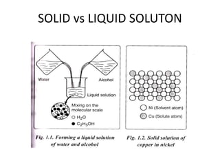
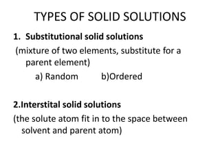
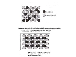
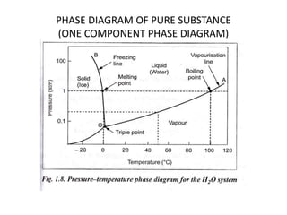
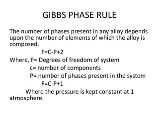
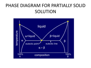
ME 8491- ENGINEERING METALLURGY
UNIT-I
CONSTITUTION OF ALLOY AND PHASE
DIAGRAMS
IMPURITIES IN SOLIDS
• Impurities are always present in all materials.
ALLOY:
• It is a mixture of two or more metals. Metal and
a non metal.
SOLID SOLUTION
• A solid solution is the simplest type of alloy.
• A solid solution may be defined as a solid that
consists of two or more elements atomically
dispersed in a single-phase structure.
1. solute: A solute is the minor part of the
solution or the material which is dissolved.
2. Solvent: Solvent constitutes the major
portion of the solution.
SOLID vs LIQUID SOLUTON
HUME ROTHERY’S RULES
• The solute and solvent follows the following
general rules:
1. Size factor (similar size)
2. Crystal structure(same crystal structure)
3. Valence (same valence)
4. Electronegativity (approximately same electro
negativity)
Size factor:
The atoms must be of similar size, with less than a
15% difference in atomic radius.
Crystal structure:
The materials must have the same crystal
structure. Otherwise, there is some point at which a
transition occurs from one phase to a second phase with
a different structure.
Valence:
The atoms must have the same valence.
Otherwise, the valence electron difference encourages
the formation of compounds rather than solutions.
Electronegativity:
Electronegativity is the ability of the atom to
attract an electron.
Possibilities of solid solutions
1. Unsaturated solid solution
2. Saturated solid solution
3. Supersaturated solid solution
TYPES OF SOLID SOLUTIONS
1. Substitutional solid solutions
(mixture of two elements, substitute for a
parent element)
a) Random b)Ordered
2.Interstital solid solutions
(the solute atom fit in to the space between
solvent and parent atom)
PHASE DIAGRAM
• Phase diagram are graphical representations
of what phases are present in a materials
system at various temperatures, pressure, and
compositions.
Terminology used in phase diagrams
1. Component
2. System
3. Alloy
4. Solid solution
5. Solute
6. Solvent
7. Phase
8. Equilibrium
9. Solubility limit
10. Degrees of freedom
PHASE DIAGRAM
PHASE DIAGRAM OF PURE SUBSTANCE
(ONE COMPONENT PHASE DIAGRAM)
GIBBS PHASE RULE
The number of phases present in any alloy depends
upon the number of elements of which the alloy is
composed.
F=C-P+2
Where, F= Degrees of freedom of system
c= number of components
P= number of phases present in the system
F=C-P+1
Where the pressure is kept constant at 1
atmosphere.
Uses of Phase Rule
• The phase rule predicts maximum number of
phases present in the alloy under equilibrium
conditions at any point of diagram.
• If number of phases are known, one can
determine the degrees of freedom using the
phase rule.
• Thus the phase rule is useful to know whether
the temperature or pressure or both variables
can be changed without changing the structure of
the alloy
PHASE DIAGRAM FOR PARTIALLY SOLID
SOLUTION
• SIX PHASES IN THE REGION
1. LIQUID PHASE
2. ALPHA SOLID SOLUTION PHASE
3. BETA SOLID SOLUTION PHASE
4. ALPHA + LIQUID PHASE
5. BETA + LIQUID PHASE
6. ALPHA + BETA SOLID SOLUTION PHASE (eutectic
point)
PHASE DIAGRAM FOR PARTIALLY SOLID
SOLUTION

Phase Diagram

  • 1.
  • 2.
    UNIT-I CONSTITUTION OF ALLOYAND PHASE DIAGRAMS
  • 3.
    IMPURITIES IN SOLIDS •Impurities are always present in all materials. ALLOY: • It is a mixture of two or more metals. Metal and a non metal.
  • 4.
    SOLID SOLUTION • Asolid solution is the simplest type of alloy. • A solid solution may be defined as a solid that consists of two or more elements atomically dispersed in a single-phase structure. 1. solute: A solute is the minor part of the solution or the material which is dissolved. 2. Solvent: Solvent constitutes the major portion of the solution.
  • 5.
  • 6.
    HUME ROTHERY’S RULES •The solute and solvent follows the following general rules: 1. Size factor (similar size) 2. Crystal structure(same crystal structure) 3. Valence (same valence) 4. Electronegativity (approximately same electro negativity)
  • 7.
    Size factor: The atomsmust be of similar size, with less than a 15% difference in atomic radius. Crystal structure: The materials must have the same crystal structure. Otherwise, there is some point at which a transition occurs from one phase to a second phase with a different structure. Valence: The atoms must have the same valence. Otherwise, the valence electron difference encourages the formation of compounds rather than solutions. Electronegativity: Electronegativity is the ability of the atom to attract an electron.
  • 8.
    Possibilities of solidsolutions 1. Unsaturated solid solution 2. Saturated solid solution 3. Supersaturated solid solution
  • 9.
    TYPES OF SOLIDSOLUTIONS 1. Substitutional solid solutions (mixture of two elements, substitute for a parent element) a) Random b)Ordered 2.Interstital solid solutions (the solute atom fit in to the space between solvent and parent atom)
  • 11.
    PHASE DIAGRAM • Phasediagram are graphical representations of what phases are present in a materials system at various temperatures, pressure, and compositions.
  • 12.
    Terminology used inphase diagrams 1. Component 2. System 3. Alloy 4. Solid solution 5. Solute 6. Solvent 7. Phase 8. Equilibrium 9. Solubility limit 10. Degrees of freedom
  • 13.
  • 14.
    PHASE DIAGRAM OFPURE SUBSTANCE (ONE COMPONENT PHASE DIAGRAM)
  • 15.
    GIBBS PHASE RULE Thenumber of phases present in any alloy depends upon the number of elements of which the alloy is composed. F=C-P+2 Where, F= Degrees of freedom of system c= number of components P= number of phases present in the system F=C-P+1 Where the pressure is kept constant at 1 atmosphere.
  • 16.
    Uses of PhaseRule • The phase rule predicts maximum number of phases present in the alloy under equilibrium conditions at any point of diagram. • If number of phases are known, one can determine the degrees of freedom using the phase rule. • Thus the phase rule is useful to know whether the temperature or pressure or both variables can be changed without changing the structure of the alloy
  • 17.
    PHASE DIAGRAM FORPARTIALLY SOLID SOLUTION • SIX PHASES IN THE REGION 1. LIQUID PHASE 2. ALPHA SOLID SOLUTION PHASE 3. BETA SOLID SOLUTION PHASE 4. ALPHA + LIQUID PHASE 5. BETA + LIQUID PHASE 6. ALPHA + BETA SOLID SOLUTION PHASE (eutectic point)
  • 18.
    PHASE DIAGRAM FORPARTIALLY SOLID SOLUTION