Downloaded 349 times


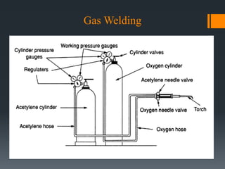
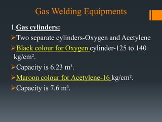
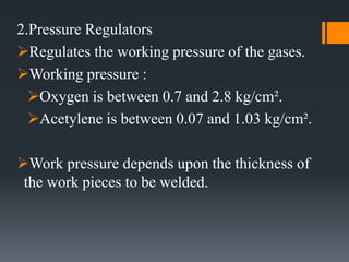
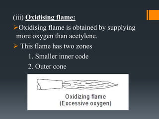
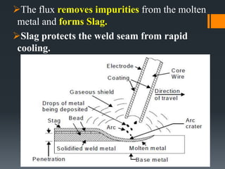


The document discusses various welding processes. It defines welding as the process of joining similar metals through the application of heat. Welding processes are classified based on the source of energy used, such as fusion welding which melts the metal, and plastic welding which heats metal to a plastic state. Specific welding techniques covered include gas welding using oxy-acetylene flames, and shielded metal arc welding where an electric arc melts the metal between an electrode and workpiece. The document provides detailed descriptions of equipment, procedures, and applications for these common welding methods.