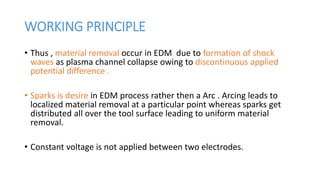
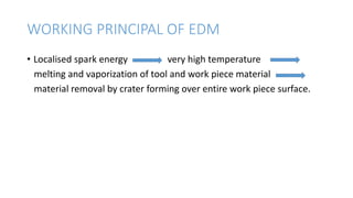
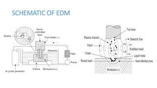
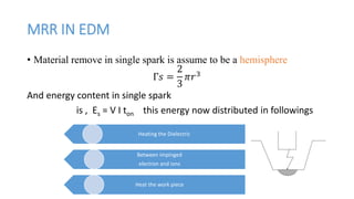
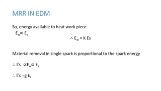
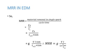
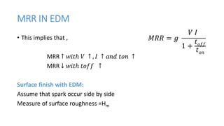
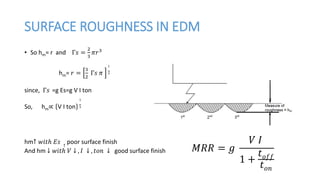
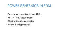
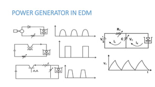
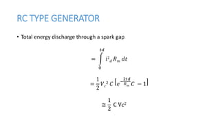
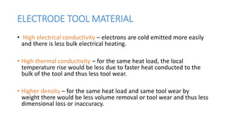
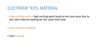
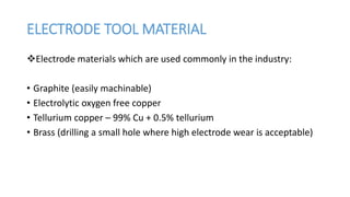
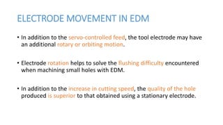
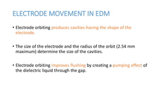
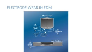
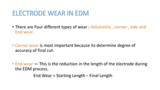
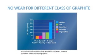
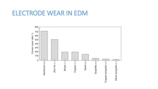
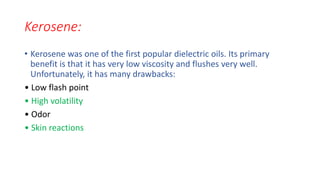
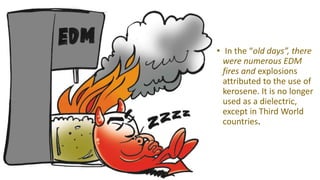
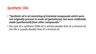
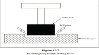
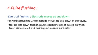
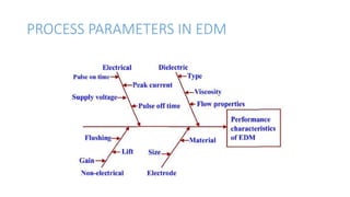
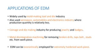
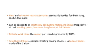
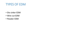
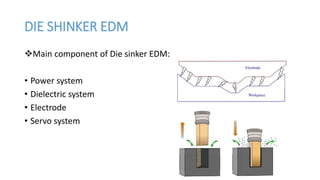
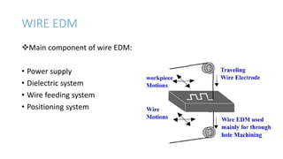
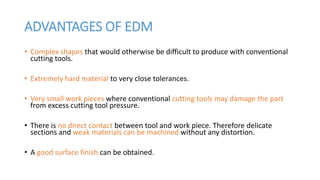
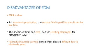
Electric
Discharge
Machine
(EDM)
Navrachana University
SET(Mech)
Presented By,
Apurva Solanki (12103304)
Dignesh Parmar (12103312)
Dipen Patel (12103314)
Jignesh Masani (12103330)
Vishal Dabgar (12103359)
History :
• In 1770 English physicists Joseph Priestly noted erosion effect of electric
discharge.
• In 1943 Two Russian scientist B.R.Lazarenko and N.I.Lazaranko found that male
and female part of electric switch has a crater from on it. And they found that if
both the electrode immersed in a dielectric erosion can be precisely controlled.
• They use this phenomena for constructive purpose and discover Electric spark
machine(EDM).
• Simultaneously American team Harold Stark , Victor Harding and Jack Beaver
developed an EDM for removing broken drills and taps form Aluminum casting .
History :
• In 1952, the manufacturer Charmilles created the first machine using the
spark machining process and was presented for the first time at the
European Machine Tool Exhibition in 1955.
• In 1969, Agie launched the world's 1st numerically controlled wire-cut EDM
machine.
• Seibu developed the first CNC wire EDM machine in 1972 and the first
system was manufactured in Japan.
• Recently, the machining speed has gone up by 20 times.
• This has decreased machining costs by at least 30 percent and improved
the surface finish by a factor of 1.5
GENERAL ASPECTS OF EDM
• Primarily used for hard metals or those that would be very difficult to machine
with traditional techniques.
• EDM typically works with materials that are electrically conductive, although
methods for machining insulating ceramics with EDM have been proposed.
• Can cut intricate contours or cavities in hardened steel without the need for heat
treatment to soften and re-harden them.
• Can also used for metal alloy such as titanium, hastelloy, kovar, and Inconel
• Also, applications of this process to shape polycrystalline diamond tools have
been reported.
WHAT IS EDM? INTRODUCTION
• Its a electro thermal non-traditional manufacturing process .
• Sometimes it is referred to as spark machining, spark eroding, burning, die
sinking or wire erosion
• Its a manufacturing process whereby a desired shape is obtained using
electrical discharges (sparks).
• Material is removed from the work piece by a series of rapidly recurring
current discharges between two electrodes, separated by a dielectric liquid
and subject to an electric voltage.
INTRODUCTION
• Two electrodes – 1) tool and other one is
2) work piece
• As distance between the two electrodes is reduced, the current intensity
becomes greater than the strength of the dielectric (at least in some
points) causing it to break.
• This allows current to flow between the two electrodes (same as a
breakdown of capacitor)
INTRODUCTION
• And material remove from the both sides
• To carried away debris (solid particles) flushing of dielectric is
required and new dielectric medium come between electrode gap.
SYSTEM OF EDM
WORKING PRINCIPLE
• Connect tool with -Ve and work material with +Ve polarities.
• Tool & work material immersed in a dielectric.
• Applied potential difference between two electrodes.
• Electric field generated between two electrodes.
• Free electron on tool subjected to electrostatic force. And according to
work function of electrons emitted from the tool (cold emission)
WORKING PRINCIPLE
• Collision take place between electron and dielectric molecules.
• Dielectric molecules ionize according to their dielectric constant &
more electrons and positive ions are generated. That leads to
increase the concentration of electron and positive ions.
• Plasma channel form between tool and work piece . Electric
resistance of this channel would be very less.
WORKING PRINCIPLE
• Thus large number of electrons and ions flows from tool to the job
and from job to the tool respectively. (avalanche motion of electron &
ions).
• Due to avalanche effect spark generated between tool and job.
• High energized electron and ions are impinged on job and tool and
their kinetic energy is converted into thermal energy on both the
sides. Instantaneous rise in temperature would be exceed of 10000⁰C.
WORKING PRINCIPLE
• Rise in temperature leads to material removal due to instant
vaporization and melting. Molten metal removed partially.
• potential difference is withdrawn.
• Plasma channel collapse ,its generates pressure and shock waves
which evacuates molten material forming crater of removed material
around the site of spark.
WORKING PRINCIPLE
• Thus , material removal occur in EDM due to formation of shock
waves as plasma channel collapse owing to discontinuous applied
potential difference .
• Sparks is desire in EDM process rather then a Arc . Arcing leads to
localized material removal at a particular point whereas sparks get
distributed all over the tool surface leading to uniform material
removal.
• Constant voltage is not applied between two electrodes.
WORKING PRINCIPAL OF EDM
• Localised spark energy very high temperature
melting and vaporization of tool and work piece material
material removal by crater forming over entire work piece surface.
SCHEMATIC OF EDM
CHARACTERISTICS OF EDM
• Work Material should be an electric conductive.
• Material removal depends on mainly thermal properties of the work
material rather than its strength, hardness etc.
• The tool has to be electrically conductive as well. The tool wear once
again depends on the thermal properties of the tool material.
• In EDM there is a physical tool and geometry of the tool is the
positive impression of the hole or geometric feature machined.
CHARACTERISTICS OF EDM
• Heat affected zone is limited to 2 – 4 μm of the spark crater
• Due to Rapid heating and cooling and local high temperature leads to
surface hardening which may be desirable in some applications.
• There is a possibility of taper cut and overcut in EDM, they can be
controlled and compensated.
MRR IN EDM
• Material remove in single spark is assume to be a hemisphere
Γ𝑠 =
2
3
𝜋𝑟3
And energy content in single spark
is , Es = V I ton this energy now distributed in followings
Heating the Dielectric
Between impinged
electron and ions
Heat the work piece
MRR IN EDM
So, energy available to heat work piece
Ew∝ Es
∴ Ew = K Es
Material removal in single spark is proportional to the spark energy
∴ Γ𝑠 ∝Ew∝ Es
∴ Γ𝑠 =g Es
MRR IN EDM
• So,
MRR =
𝑚𝑎𝑡𝑒𝑟𝑖𝑎𝑙 𝑟𝑒𝑚𝑜𝑣𝑎𝑙 𝑖𝑛 𝑠𝑖𝑛𝑔𝑙𝑒 𝑠𝑝𝑎𝑟𝑘
𝑐𝑦𝑐𝑙𝑒 𝑡𝑖𝑚𝑒
=
Γ𝑠
𝑡 𝑐
=
Γ𝑠
𝑡 𝑜𝑓𝑓
+𝑡𝑜𝑛
= g
𝑉 𝐼 𝑡𝑜𝑛
𝑡 𝑜𝑓𝑓
+𝑡𝑜𝑛
∴ 𝑀𝑅𝑅 = 𝑔
𝑉 𝐼
1+
𝑡 𝑜𝑓𝑓
𝑡 𝑜𝑛
MRR IN EDM
• This implies that ,
MRR ↑ 𝑤𝑖𝑡ℎ 𝑉 ↑ , 𝐼 ↑ 𝑎𝑛𝑑 𝑡𝑜𝑛 ↑
MRR ↓ 𝑤𝑖𝑡ℎ 𝑡𝑜𝑓𝑓 ↑
Surface finish with EDM:
Assume that spark occur side by side
Measure of surface roughness =Hm
𝑀𝑅𝑅 = 𝑔
𝑉 𝐼
1 +
𝑡 𝑜𝑓𝑓
𝑡 𝑜𝑛
SURFACE ROUGHNESS IN EDM
• So hm= r and Γ𝑠 =
2
3
𝜋𝑟3
hm= 𝑟 =
3
2
Γ𝑠 𝜋
1
3
since, Γ𝑠 =g Es=g V I ton
So, hm∝ V I ton
1
3
hm↑ 𝑤𝑖𝑡ℎ 𝐸𝑠 ↑
poor surface finish
And hm ↓ 𝑤𝑖𝑡ℎ 𝑉 ↓ , 𝐼 ↓ , 𝑡𝑜𝑛 ↓ good surface finish 𝑀𝑅𝑅 = 𝑔
𝑉 𝐼
1 +
𝑡 𝑜𝑓𝑓
𝑡 𝑜𝑛
POWER GENERATOR IN EDM
• Resistance capacitance type (RC)
• Rotary impulse generator
• Electronic pulse generator
• Hybrid EDM generator
POWER GENERATOR IN EDM
RC TYPE GENERATOR
During charging of capacitor
𝑐
𝑑𝑉
𝑑𝑡
=
𝑉0
−𝑉𝑐
𝑅 𝑐
1
𝑉0
−𝑉𝑐
=
1
𝐶𝑅 𝑐
𝑑𝑡
Integrating this equation
At t=0 , Vc=0 and at t=tc , Vc=Vc
*
𝑉 𝑐 = 𝑉0 1 − 𝑒−
𝑡 𝑐
𝐶𝑅𝑐 and charging current 𝑖 𝑐 = 𝑖0 𝑒−
𝑡
𝐶𝑅 𝑐
Where,
Ic= charging current
V0= open circuit voltage
Vc=instantaneous voltage during
charging
C=capacitance
Rc= charging resistance
RC TYPE GENERATOR
• During discharging capacitor
𝑖 𝑑 =
𝑉 𝑐
𝑅 𝑚
= −C
𝑑𝑉𝑐
𝑑𝑡
Integrating, at t=0 ,Vc=Vc
*
t=td , Vc=Vd
*
We got ,
𝑉𝑑
∗
= 𝑉𝑐
∗
𝑒
−
𝑡 𝑑
Rm and 𝑖 𝑑 =
𝑉 𝑐
∗
𝑅 𝑚
𝑒−
𝑡 𝑑
𝐶 𝑅𝑚
Vc = capacitor voltage during
discharging
Id = discharging current
Rm= machine resistance
RC TYPE GENERATOR
• For maximum power dissipation in RC type EDM
𝑉 𝑐 = 0.716 𝑉0
• Charging time/ideal time /off time
𝑡 𝑐 = −
𝑅 𝑐 𝐶
ln 1 −
𝑉 𝑐 ∗
𝑉 𝑐
• Discharging time ,
𝑡 𝑑 = −
𝑅 𝑐 𝐶
ln
𝑉 𝑑
∗
𝑉 𝑑
RC TYPE GENERATOR
• Frequency of operation
𝑓 =
1
𝑡 𝑐 + 𝑡𝑑
=
1
−
𝑅 𝑐 𝐶
ln 1 −
𝑉 𝑐 ∗
𝑉 𝑐
−
𝑅 𝑐 𝐶
ln
𝑉 𝑑
∗
𝑉 𝑑
RC TYPE GENERATOR
• Total energy discharge through a spark gap
=
0
𝑡𝑑
𝑖2
𝑑 𝑅 𝑚 𝑑𝑡
=
1
2
𝑉 𝑐
2 𝐶 𝑒−
2𝑡𝑑
𝑅 𝑚 𝐶 − 1
≅
1
2
C Vc2
ELECTRODE TOOL MATERIAL
• High electrical conductivity – electrons are cold emitted more easily
and there is less bulk electrical heating.
• High thermal conductivity – for the same heat load, the local
temperature rise would be less due to faster heat conducted to the
bulk of the tool and thus less tool wear.
• Higher density – for the same heat load and same tool wear by
weight there would be less volume removal or tool wear and thus less
dimensional loss or inaccuracy.
ELECTRODE TOOL MATERIAL
• High melting point – high melting point leads to less tool wear due to
less tool material melting for the same heat load.
• Easy manufacturability.
• Cost – cheap.
ELECTRODE TOOL MATERIAL
Electrode materials which are used commonly in the industry:
• Graphite (easily machinable)
• Electrolytic oxygen free copper
• Tellurium copper – 99% Cu + 0.5% tellurium
• Brass (drilling a small hole where high electrode wear is acceptable)
ELECTRODE MOVEMENT IN EDM
• In addition to the servo-controlled feed, the tool electrode may have
an additional rotary or orbiting motion.
• Electrode rotation helps to solve the flushing difficulty encountered
when machining small holes with EDM.
• In addition to the increase in cutting speed, the quality of the hole
produced is superior to that obtained using a stationary electrode.
ELECTRODE MOVEMENT IN EDM
• Electrode orbiting produces cavities having the shape of the
electrode.
• The size of the electrode and the radius of the orbit (2.54 mm
maximum) determine the size of the cavities.
• Electrode orbiting improves flushing by creating a pumping effect of
the dielectric liquid through the gap.
ELECTRODE WEAR IN EDM
• There are Four different types of wear : Volumetric , corner , side and
End wear.
• Corner wear is most important because its determine degree of
accuracy of final cut.
• End wear — This is the reduction in the length of the electrode during
the EDM process.
End Wear = Starting Length – Final Length
ELECTRODE WEAR IN EDM
• 𝐸𝑛𝑑 𝑤𝑒𝑎𝑟 𝑟𝑎𝑡𝑖𝑜 =
𝐷𝑒𝑝𝑡ℎ 𝑜𝑓 𝑐𝑢𝑡
𝐸𝑛𝑑 𝑤𝑒𝑎𝑟
% 𝑜𝑓 𝐸𝑛𝑑 𝑤𝑒𝑎𝑟 =
100
𝐸𝑛𝑑 𝑤𝑒𝑎𝑟
• Corner wear — Electromagnetic fields tend to concentrate at the electrode corners ,
subjecting the corners to greater wear.
• The sharper the angle more corner wear but at Blunt corners will wear less than sharp
angle corners.
• Corner wear can be minimized by choosing a small particle size electrode material that
has high strength and high density.
ELECTRODE WEAR IN EDM
• Corner Wear = Apparent Corner Wear + End Wear
Corner 𝑤𝑒𝑎𝑟 𝑟𝑎𝑡𝑖𝑜 =
𝐷𝑒𝑝𝑡ℎ 𝑜𝑓 𝑐𝑢𝑡
𝐸𝑛𝑑 𝑤𝑒𝑎𝑟
• 𝑉𝑜𝑙𝑢𝑚𝑒𝑡𝑟𝑖𝑐 𝑤𝑒𝑎𝑟 =
𝑉𝑜𝑙𝑢𝑚𝑒 𝑜𝑓 𝑤𝑜𝑟𝑘𝑚𝑒𝑡𝑎𝑙 𝑟𝑒𝑚𝑜𝑣𝑒𝑑
𝑉𝑜𝑙𝑢𝑚𝑒 𝑜𝑓 𝑒𝑙𝑒𝑐𝑡𝑟𝑜𝑑𝑒 𝑙𝑜𝑠𝑠
• Side wear — This is wear along the side walls of the electrode.
ELECTRODE WEAR IN EDM
• Electrode wear depends on a number of factors associated with the EDM,
like voltage, current, electrode material, and polarity.
• The melting point is the most important factor in determining the tool
wear.
• No wear EDM: No-wear EDMing is considered to be 1% or less electrode
wear.
• Parameters necessary for a no-wear condition with graphite electrodes is
positive polarity and long on-times. The off-time is set as short as possible.
NO WEAR EDM
• During the machining electrode will take on silvery coating due to
work metal plating on electrode.
• More plating causes electrode to grow and its form nodules that will
distort the shape of electrode.
• No wear is not leads to faster material removal rates.
• No wear conditions is only with possible with graphite electrode
NO WEAR FOR DIFFERENT CLASS OF GRAPHITE
approximate minimumon-time required to achieve a no-wear
condition for each class of graphite.
ELECTRODE WEAR IN EDM
• The wear rate of the electrode tool material (Wt) and the wear ratio
(Rw) are given by Kalpakjian (1997).
Dielectric fluid:
• What is Dielectric fluid?
• Why it is used?
• When it is used?
• Types of Dielectric fluid
• Which Properties & Characteristics Dielectric fluids have ?
What is dielectric fluid…??
• A dielectric is a non-conducting substance, i.e. an insulator. Although
"dielectric" and "insulator" are generally considered synonymous,
• The dielectric fluid must be circulated under constant pressure to
flush (wash) away the metal particles and assist in the machining or
erosion process.
Function of dielectric fluid:
• The dielectric oil acts as a medium through which controlled electrical
discharges occur.
• The dielectric oil acts as a quenching medium to cool and solidify the
gaseous EDM debris resulting from the discharge.
• The dielectric oil acts as a medium used to carry away the solidified
EDM debris from the discharge gap to the filter system.
• The dielectric oil acts as a heat transfer medium to absorb and carry
away the heat generated by the discharges from both the electrode
and the workpiece.
Requirements of Dielectric Fluid:
1. The dielectic fluid should have sufficient stable dielectric strength to
provide insulation between the tool and work piece till the breakdown
voltage is reached.
2. After the spark Discharge has taken place fluid should de-ionise.
3. It should have low viscosity and a good wetting capacity to provide
effective cooling mechanism.
4. It should flush out the particles produced during the spark out of the
gap. This is the most important function of dielectric fluid . Inadequate
flushing can result in decreasing the life of the electrode and increasing
the machining time.
5. It should be chemically neutral so as not to react with the electrode , the
work piece , the worktable or the tank.
Continue….
6. The flash point should be high so that there are no fire hazards.
7. Neither emission of any toxic vapours nor unpleasant odours are
desirable.
8. It should maintain their properties with temperature variation,
contamination by working residuals and products of decomposition.
9. It should be economical and easily available.
Properties & Characteristics of Dielectric Oils:
• Viscosity
• Flash Point
• Dielectric Strength
• Pour Point
• Volatility
• Oxidation Stability
• Acid Number
• Odor
• Color
Viscosity
• Viscosity is the property that describes a fluids resistance to flow.
• Viscosity is commonly measured by two different units:
1. Centistokes (cST)
2. Saybolt Universal Seconds (SUS)
The system used, a lower number means a thinner (less viscous) fluid.
Generally, a thinner fluid will flush better than a thicker fluid, and for
most oils, the oil will get thinner as the oil temperature increases.
Flash Point
• “The flash point of a flammable liquid is the lowest temperature at which
it can form an ignitable mixture in air.”
• The Flash Point is usually reported in units of ⁰ F and is often measured by
the Cleveland Open Cup (COC) procedure.
• Flash points for common liquids are listed below:
• Gasoline -40⁰ F
• Ethanol 55⁰ F
• Kerosene 120⁰ F
• Diesel 143⁰ F
• Vegetable Oil 620⁰ F
• The flash point for commonly used EDM dielectric oils ranges from 160 ⁰ F
to 255 ⁰ F.
• Obviously for reasons of safety, the higher the flashpoint the better.
Flash Point
• When a liquid petroleum product is exposed to air, some of it
evaporates, causing a certain vapour/air concentration. As the
temperature of the liquid product is raised more and more
evaporates and the vapour/air ratio increases. Eventually, a
temperature is reached at which the vapour air ratio is high enough
to support momentary combustion, if a source of ignition is present.
This temperature is the Flash Point of the product.
Dielectric Strength:
• For a given configuration of dielectric material and electrodes, the
dielectric strength is the minimum electrical field that produces
breakdown.
• The dielectric strength is commonly measured in units of either
MV/m, or V/mil.
Pour Point
• The pour point of an oil is the temperature below which the oil no
longer pours freely.
• This is also sometimes called the gel point, since at temperatures
below the gel point the oil begins to gel.
• The pour point is usually stated in units of ⁰F.
• Since EDM oil is normally used at or above room temperature, one
might surmise that this property is not worthy of consideration.
• However, if your drums of dielectric fluid are stored in an unheated
area in the winter, and that fluid has a relatively high pour point, the
dielectric will gel and cannot be pumped from the drum until it is
warmed to room temperature.
Volatility:
• Volatility is a measure of the tendency of a dielectric fluid to vaporize.
• While most all dielectric fluids will exhibit some degree of
evaporation, the more volatile dielectric fluids will evaporate
significantly more rapidly than their less volatile cousins.
• Volatility in dielectric oils is generally related to flash point.
Oxidation Stability:
• Oxidation stability is a measure of the dielectric fluids tendency to
react with oxygen.
• Having greater oxidation stability means that the dielectric fluid will
resist degradation longer, retaining its clarity, initial viscosity, and give
longer service life.
Acid Number:
• The acid number is used to quantify the amount of acid present in a
sample of dielectric oil.
• Excessive levels of acid in a dielectric oil could lead to corrosion in the
dielectric system.
• The acid number is expressed in units of mg KOH/g, or the amount of
Sodium Hydroxide necessary to neutralize the acid present in an oil
sample.
Odor:
• The odor of a dielectric fluid is an important property, especially for
those that work with or near the dielectric fluid.
• there is no standard measure or specification of dielectric odor.
Color:
• The color of a dielectric oil can be classified by an ASTM test.
• Ideally, a dielectric fluid should be water white for maximum visibility
of the workpiece.
List of dielectric fluid:
• There are currently numerous choices of mineral oils formulated
specifically for EDM. They are available with a wide range of
properties and pricing.
Examples..
• Mineral Oils
• Kerosene
• deionised water
• Synthetic Oils
• Silicone Oils
Mineral Oils:
• Mineral oil or liquid petroleum is a by-product in the distillation of
petroleum.
Kerosene:
• Kerosene was one of the first popular dielectric oils. Its primary
benefit is that it has very low viscosity and flushes very well.
Unfortunately, it has many drawbacks:
• Low flash point
• High volatility
• Odor
• Skin reactions
• In the “old days”, there
were numerous EDM
fires and explosions
attributed to the use of
kerosene. It is no longer
used as a dielectric,
except in Third World
countries.
deionised water
• Tap water cannot be used as it ionises too early and thus breakdown
due to presence of salts as impurities occur.
Synthetic Oils
• “Synthetic oil is oil consisting of chemical compounds which were
not originally present in crude oil (petroleum), but were artificially
made (synthesized) from other compounds.”
• the cost of a synthetic EDM oil is almost double that of a mineral oil,
the life is usually double that of a mineral oil
Benefits of Synthetic Oils
• Longer life
• Low evaporation and volatility
• Extremely low odor
• Improved health and safety for operators
Silicone Oils
• In those instances where mineral and synthetic oils cannot be used,
such as the previously mentioned aerospace application in which the
solvent action of the oil is not tolerated by the wax filler material,
silicone based EDM oil is used. Silcone oil works well as an EDM
dielectric but is very expensive, limiting its use to specialty
applications.
Flushing in EDM
The adage
“The three most important things in
EDM are: Flushing, Flushing, and
Flushing”
What is flushing…?
• Flushing is the process of introducing clean filtered dielectric fluid into
the spark gap.
• One of the most important factors in a successful EDM operation is
the removal of the metal particles (chips) from the working gap.
Why it is so important…?
i. Flushing particles out of the gap between the work piece to
prevent them from forming bridges that cause short circuits.
ii. Flushing applied incorrectly can result in erratic cutting and poor
machining conditions.
Continue…
• while assisting in the machining process, too much fluid pressure will
remove the chips before they can assist in the cutting action, resulting
in slower metal removal, too little pressure will not remove the chips
quickly enough and may result in short-circuiting the erosion process
Flushing:
 Synchronized, pulsed flushing is also available on some machines.
 With this method, flushing occurs only during the non-machining time as the electrode is
retracted slightly to enlarge the gap.
 Increased electrode life has been reported with this system.
 Innovative techniques such as ultrasonic vibrations coupled with mechanical pulse EDM,
jet flushing with sweeping nozzles, and electrode pulsing are investigated by Masuzawa
(1990).
Flushing:
 For proper flushing conditions, Metals Handbook (1989) recommends:
1. Flushing through the tool is more preferred than side flushing.
2. Many small flushing holes are better than a few large ones.
3. Steady dielectric flow on the entire workpiece-electrode interface is desirable.
4. Dead spots created by pressure flushing, from opposite sides of the workpiece, should be
avoided.
5. A vent hole should be provided for any upwardly concave part of the tool-electrode to
prevent accumulation of explosive gases.
6. A flush box is useful if there is a hole in the cavity.
Flushing:
• Proper flushing depends on the volume of oil being flushed into the
gap, rather than the flushing pressure.
• High flushing pressure can also cause excessive electrode wear by
making the erode particals bounce around in the cavity.
• Generally ,the ideal flushing pressure is between 3 to 5psi.(0.2 to 0.33
bars)
• Efficient flushing requires a balance between volume and pressure.
Function of dielectric fluid:
flushing
Pressure
Through the electrode
Through the
work piece
Suction Pulse
Vertical flushing
Rotary flushing
Orbiting flushing
Jet
Flushing-types
1.Pressure flushing:
pressure flushing, also called injection flushing, is the most common
and preferred method for flushing.
The great advantage of the pressure flushing is that the operator can
visually see the amount of oil that being used for flushing.
With pressure gauges, this method of flushing is simple to learn and
use
Pressure flushing:
1.Pressure flushing through the electrode
With pressure flushing, there is the danger of a secondary discharge .since
electricity takes the path of least resistance, secondary discharge
machining can occur as the erode particles pass between the walls of the
electrode and the work piece, secondary discharge can cause side wall
tapering. Suction flushing can prevent side wall tapering
Pressure flushing:
2.Pressure flushing through the work piece:
Pressure flushing can also be done by forcing the dielectric fluid
through a work piece mounted over a flushing pot.
This method eliminates the need for holes in the dielectric
2.Suction flushing:
• Suction or vacuum flushing can be used to remove eroded gap
particles. suction flushing can be done through the electrode or
through the work piece.
• Suction flushing minimizes secondary discharge and wall tapering.
• Suction flushing sucks oil from the work tank, not from the clean
filtered oil as in pressure flushing.
2.Suction flushing:
• For suction cutting, efficient cutting is best accomplished when the
work tank oil is clean.
• A disadvantage of suction flushing is that there is no visible oil stream
as with pressure flushing.
3.Jet flushing:
• Jet or side flushing is done by tubes or flushing nozzles which direct
the dielectric fluid in to the gap
• Pulse flushing usually used with jet flushing.
4.Pulse flushing :
1.Vertical flushing : Electrode moves up and down
• In vertical flushing ,the electrode moves up and down in the cavity.
• this up and down motion cause a pumping action which draws in
fresh dielectric oil and flushing out eroded particales
4.Pulse flushing :
2.Rotary flushing : Electrode rotates
• In Rotary flushing the electrode rotates in the cavity .
• Rotating the electrode aids in flushing out the EDM particles from the
cavity .
4.Pulse flushing :
Multiple cavities for Rotary EDMing:
• For small round electrodes , manufactures make multiple cavities in
these electrodes to aid in flushing. This is a very efficient method of
producing holes without a stud.
4.Pulse flushing :
3.Orbiting flushing : The electrode orbits
• Orbiting an electrode in a cavity allows the electrode to mechanically
force the eroded particle from the cavity
• Orbiting flushing is the most efficient for cutting.
• If the orbiting is larger than the radius of the radius of the flushing holes
in the electrode, it will produce no stud
Flushing through hole in tool
• Result in Spike formation on work piece .
• It can be avoided by rotating tool with eccentric holes.
SPIKE
PROCESS PARAMETERS IN EDM
APPLICATIONS OF EDM
• Widely used by mold-making tool and die industry
• Also used aerospace, automobiles and electronics industry where
production quantity is relatively less.
• Coinage and die making industry for producing jewelry and badges.
• Metal disintegration machining for removing broken drills, taps bolt , studs
etc. from work piece.
• EDM can be economically employed for extremely hardened work piece.
• Hard and corrosion resistant surfaces, essentially needed for die making,
can be developed.
• Can be applied to all electrically conducting metals and alloys irrespective
of their melting points, hardness, toughness, or brittleness.
• Delicate work piece like copper parts can be produced by EDM.
• Small hole drilling , example: Creating cooling channels in turbine blades
made of hard alloys.
TYPES OF EDM
• Die sinker EDM
• Wire cut EDM
• Powder EDM
DIE SHINKER EDM
Main component of Die sinker EDM:
• Power system
• Dielectric system
• Electrode
• Servo system
WIRE EDM
Main component of wire EDM:
• Power supply
• Dielectric system
• Wire feeding system
• Positioning system
ADVANTAGES OF EDM
• Complex shapes that would otherwise be difficult to produce with conventional
cutting tools.
• Extremely hard material to very close tolerances.
• Very small work pieces where conventional cutting tools may damage the part
from excess cutting tool pressure.
• There is no direct contact between tool and work piece. Therefore delicate
sections and weak materials can be machined without any distortion.
• A good surface finish can be obtained.
DISADVANTAGES OF EDM
• MRR is slow
• For economic production, the surface finish specified should not be
too fine.
• The additional time and cost used for creating electrodes for
ram/sinker EDM.
• Reproducing sharp corners on the work piece is difficult due to
electrode wear.
DISADVANTAGES OF EDM
• Specific power consumption is very high.
• "Overcut" is formed.
• Excessive tool wear occurs during machining.
• Electrically non-conductive materials can be machined only with
specific set-up of the process .
THANK YOU

Introduction to Electric Discharge Machining

  • 1.
    Electric Discharge Machine (EDM) Navrachana University SET(Mech) Presented By, ApurvaSolanki (12103304) Dignesh Parmar (12103312) Dipen Patel (12103314) Jignesh Masani (12103330) Vishal Dabgar (12103359)
  • 2.
    History : • In1770 English physicists Joseph Priestly noted erosion effect of electric discharge. • In 1943 Two Russian scientist B.R.Lazarenko and N.I.Lazaranko found that male and female part of electric switch has a crater from on it. And they found that if both the electrode immersed in a dielectric erosion can be precisely controlled. • They use this phenomena for constructive purpose and discover Electric spark machine(EDM). • Simultaneously American team Harold Stark , Victor Harding and Jack Beaver developed an EDM for removing broken drills and taps form Aluminum casting .
  • 3.
    History : • In1952, the manufacturer Charmilles created the first machine using the spark machining process and was presented for the first time at the European Machine Tool Exhibition in 1955. • In 1969, Agie launched the world's 1st numerically controlled wire-cut EDM machine. • Seibu developed the first CNC wire EDM machine in 1972 and the first system was manufactured in Japan. • Recently, the machining speed has gone up by 20 times. • This has decreased machining costs by at least 30 percent and improved the surface finish by a factor of 1.5
  • 4.
    GENERAL ASPECTS OFEDM • Primarily used for hard metals or those that would be very difficult to machine with traditional techniques. • EDM typically works with materials that are electrically conductive, although methods for machining insulating ceramics with EDM have been proposed. • Can cut intricate contours or cavities in hardened steel without the need for heat treatment to soften and re-harden them. • Can also used for metal alloy such as titanium, hastelloy, kovar, and Inconel • Also, applications of this process to shape polycrystalline diamond tools have been reported.
  • 5.
    WHAT IS EDM?INTRODUCTION • Its a electro thermal non-traditional manufacturing process . • Sometimes it is referred to as spark machining, spark eroding, burning, die sinking or wire erosion • Its a manufacturing process whereby a desired shape is obtained using electrical discharges (sparks). • Material is removed from the work piece by a series of rapidly recurring current discharges between two electrodes, separated by a dielectric liquid and subject to an electric voltage.
  • 6.
    INTRODUCTION • Two electrodes– 1) tool and other one is 2) work piece • As distance between the two electrodes is reduced, the current intensity becomes greater than the strength of the dielectric (at least in some points) causing it to break. • This allows current to flow between the two electrodes (same as a breakdown of capacitor)
  • 7.
    INTRODUCTION • And materialremove from the both sides • To carried away debris (solid particles) flushing of dielectric is required and new dielectric medium come between electrode gap.
  • 8.
  • 9.
    WORKING PRINCIPLE • Connecttool with -Ve and work material with +Ve polarities. • Tool & work material immersed in a dielectric. • Applied potential difference between two electrodes. • Electric field generated between two electrodes. • Free electron on tool subjected to electrostatic force. And according to work function of electrons emitted from the tool (cold emission)
  • 10.
    WORKING PRINCIPLE • Collisiontake place between electron and dielectric molecules. • Dielectric molecules ionize according to their dielectric constant & more electrons and positive ions are generated. That leads to increase the concentration of electron and positive ions. • Plasma channel form between tool and work piece . Electric resistance of this channel would be very less.
  • 11.
    WORKING PRINCIPLE • Thuslarge number of electrons and ions flows from tool to the job and from job to the tool respectively. (avalanche motion of electron & ions). • Due to avalanche effect spark generated between tool and job. • High energized electron and ions are impinged on job and tool and their kinetic energy is converted into thermal energy on both the sides. Instantaneous rise in temperature would be exceed of 10000⁰C.
  • 12.
    WORKING PRINCIPLE • Risein temperature leads to material removal due to instant vaporization and melting. Molten metal removed partially. • potential difference is withdrawn. • Plasma channel collapse ,its generates pressure and shock waves which evacuates molten material forming crater of removed material around the site of spark.
  • 13.
    WORKING PRINCIPLE • Thus, material removal occur in EDM due to formation of shock waves as plasma channel collapse owing to discontinuous applied potential difference . • Sparks is desire in EDM process rather then a Arc . Arcing leads to localized material removal at a particular point whereas sparks get distributed all over the tool surface leading to uniform material removal. • Constant voltage is not applied between two electrodes.
  • 14.
    WORKING PRINCIPAL OFEDM • Localised spark energy very high temperature melting and vaporization of tool and work piece material material removal by crater forming over entire work piece surface.
  • 15.
  • 16.
    CHARACTERISTICS OF EDM •Work Material should be an electric conductive. • Material removal depends on mainly thermal properties of the work material rather than its strength, hardness etc. • The tool has to be electrically conductive as well. The tool wear once again depends on the thermal properties of the tool material. • In EDM there is a physical tool and geometry of the tool is the positive impression of the hole or geometric feature machined.
  • 17.
    CHARACTERISTICS OF EDM •Heat affected zone is limited to 2 – 4 μm of the spark crater • Due to Rapid heating and cooling and local high temperature leads to surface hardening which may be desirable in some applications. • There is a possibility of taper cut and overcut in EDM, they can be controlled and compensated.
  • 18.
    MRR IN EDM •Material remove in single spark is assume to be a hemisphere Γ𝑠 = 2 3 𝜋𝑟3 And energy content in single spark is , Es = V I ton this energy now distributed in followings Heating the Dielectric Between impinged electron and ions Heat the work piece
  • 19.
    MRR IN EDM So,energy available to heat work piece Ew∝ Es ∴ Ew = K Es Material removal in single spark is proportional to the spark energy ∴ Γ𝑠 ∝Ew∝ Es ∴ Γ𝑠 =g Es
  • 20.
    MRR IN EDM •So, MRR = 𝑚𝑎𝑡𝑒𝑟𝑖𝑎𝑙 𝑟𝑒𝑚𝑜𝑣𝑎𝑙 𝑖𝑛 𝑠𝑖𝑛𝑔𝑙𝑒 𝑠𝑝𝑎𝑟𝑘 𝑐𝑦𝑐𝑙𝑒 𝑡𝑖𝑚𝑒 = Γ𝑠 𝑡 𝑐 = Γ𝑠 𝑡 𝑜𝑓𝑓 +𝑡𝑜𝑛 = g 𝑉 𝐼 𝑡𝑜𝑛 𝑡 𝑜𝑓𝑓 +𝑡𝑜𝑛 ∴ 𝑀𝑅𝑅 = 𝑔 𝑉 𝐼 1+ 𝑡 𝑜𝑓𝑓 𝑡 𝑜𝑛
  • 21.
    MRR IN EDM •This implies that , MRR ↑ 𝑤𝑖𝑡ℎ 𝑉 ↑ , 𝐼 ↑ 𝑎𝑛𝑑 𝑡𝑜𝑛 ↑ MRR ↓ 𝑤𝑖𝑡ℎ 𝑡𝑜𝑓𝑓 ↑ Surface finish with EDM: Assume that spark occur side by side Measure of surface roughness =Hm 𝑀𝑅𝑅 = 𝑔 𝑉 𝐼 1 + 𝑡 𝑜𝑓𝑓 𝑡 𝑜𝑛
  • 22.
    SURFACE ROUGHNESS INEDM • So hm= r and Γ𝑠 = 2 3 𝜋𝑟3 hm= 𝑟 = 3 2 Γ𝑠 𝜋 1 3 since, Γ𝑠 =g Es=g V I ton So, hm∝ V I ton 1 3 hm↑ 𝑤𝑖𝑡ℎ 𝐸𝑠 ↑ poor surface finish And hm ↓ 𝑤𝑖𝑡ℎ 𝑉 ↓ , 𝐼 ↓ , 𝑡𝑜𝑛 ↓ good surface finish 𝑀𝑅𝑅 = 𝑔 𝑉 𝐼 1 + 𝑡 𝑜𝑓𝑓 𝑡 𝑜𝑛
  • 23.
    POWER GENERATOR INEDM • Resistance capacitance type (RC) • Rotary impulse generator • Electronic pulse generator • Hybrid EDM generator
  • 24.
  • 25.
    RC TYPE GENERATOR Duringcharging of capacitor 𝑐 𝑑𝑉 𝑑𝑡 = 𝑉0 −𝑉𝑐 𝑅 𝑐 1 𝑉0 −𝑉𝑐 = 1 𝐶𝑅 𝑐 𝑑𝑡 Integrating this equation At t=0 , Vc=0 and at t=tc , Vc=Vc * 𝑉 𝑐 = 𝑉0 1 − 𝑒− 𝑡 𝑐 𝐶𝑅𝑐 and charging current 𝑖 𝑐 = 𝑖0 𝑒− 𝑡 𝐶𝑅 𝑐 Where, Ic= charging current V0= open circuit voltage Vc=instantaneous voltage during charging C=capacitance Rc= charging resistance
  • 26.
    RC TYPE GENERATOR •During discharging capacitor 𝑖 𝑑 = 𝑉 𝑐 𝑅 𝑚 = −C 𝑑𝑉𝑐 𝑑𝑡 Integrating, at t=0 ,Vc=Vc * t=td , Vc=Vd * We got , 𝑉𝑑 ∗ = 𝑉𝑐 ∗ 𝑒 − 𝑡 𝑑 Rm and 𝑖 𝑑 = 𝑉 𝑐 ∗ 𝑅 𝑚 𝑒− 𝑡 𝑑 𝐶 𝑅𝑚 Vc = capacitor voltage during discharging Id = discharging current Rm= machine resistance
  • 27.
    RC TYPE GENERATOR •For maximum power dissipation in RC type EDM 𝑉 𝑐 = 0.716 𝑉0 • Charging time/ideal time /off time 𝑡 𝑐 = − 𝑅 𝑐 𝐶 ln 1 − 𝑉 𝑐 ∗ 𝑉 𝑐 • Discharging time , 𝑡 𝑑 = − 𝑅 𝑐 𝐶 ln 𝑉 𝑑 ∗ 𝑉 𝑑
  • 28.
    RC TYPE GENERATOR •Frequency of operation 𝑓 = 1 𝑡 𝑐 + 𝑡𝑑 = 1 − 𝑅 𝑐 𝐶 ln 1 − 𝑉 𝑐 ∗ 𝑉 𝑐 − 𝑅 𝑐 𝐶 ln 𝑉 𝑑 ∗ 𝑉 𝑑
  • 29.
    RC TYPE GENERATOR •Total energy discharge through a spark gap = 0 𝑡𝑑 𝑖2 𝑑 𝑅 𝑚 𝑑𝑡 = 1 2 𝑉 𝑐 2 𝐶 𝑒− 2𝑡𝑑 𝑅 𝑚 𝐶 − 1 ≅ 1 2 C Vc2
  • 30.
    ELECTRODE TOOL MATERIAL •High electrical conductivity – electrons are cold emitted more easily and there is less bulk electrical heating. • High thermal conductivity – for the same heat load, the local temperature rise would be less due to faster heat conducted to the bulk of the tool and thus less tool wear. • Higher density – for the same heat load and same tool wear by weight there would be less volume removal or tool wear and thus less dimensional loss or inaccuracy.
  • 31.
    ELECTRODE TOOL MATERIAL •High melting point – high melting point leads to less tool wear due to less tool material melting for the same heat load. • Easy manufacturability. • Cost – cheap.
  • 32.
    ELECTRODE TOOL MATERIAL Electrodematerials which are used commonly in the industry: • Graphite (easily machinable) • Electrolytic oxygen free copper • Tellurium copper – 99% Cu + 0.5% tellurium • Brass (drilling a small hole where high electrode wear is acceptable)
  • 33.
    ELECTRODE MOVEMENT INEDM • In addition to the servo-controlled feed, the tool electrode may have an additional rotary or orbiting motion. • Electrode rotation helps to solve the flushing difficulty encountered when machining small holes with EDM. • In addition to the increase in cutting speed, the quality of the hole produced is superior to that obtained using a stationary electrode.
  • 34.
    ELECTRODE MOVEMENT INEDM • Electrode orbiting produces cavities having the shape of the electrode. • The size of the electrode and the radius of the orbit (2.54 mm maximum) determine the size of the cavities. • Electrode orbiting improves flushing by creating a pumping effect of the dielectric liquid through the gap.
  • 35.
  • 36.
    ELECTRODE WEAR INEDM • There are Four different types of wear : Volumetric , corner , side and End wear. • Corner wear is most important because its determine degree of accuracy of final cut. • End wear — This is the reduction in the length of the electrode during the EDM process. End Wear = Starting Length – Final Length
  • 37.
    ELECTRODE WEAR INEDM • 𝐸𝑛𝑑 𝑤𝑒𝑎𝑟 𝑟𝑎𝑡𝑖𝑜 = 𝐷𝑒𝑝𝑡ℎ 𝑜𝑓 𝑐𝑢𝑡 𝐸𝑛𝑑 𝑤𝑒𝑎𝑟 % 𝑜𝑓 𝐸𝑛𝑑 𝑤𝑒𝑎𝑟 = 100 𝐸𝑛𝑑 𝑤𝑒𝑎𝑟 • Corner wear — Electromagnetic fields tend to concentrate at the electrode corners , subjecting the corners to greater wear. • The sharper the angle more corner wear but at Blunt corners will wear less than sharp angle corners. • Corner wear can be minimized by choosing a small particle size electrode material that has high strength and high density.
  • 38.
    ELECTRODE WEAR INEDM • Corner Wear = Apparent Corner Wear + End Wear Corner 𝑤𝑒𝑎𝑟 𝑟𝑎𝑡𝑖𝑜 = 𝐷𝑒𝑝𝑡ℎ 𝑜𝑓 𝑐𝑢𝑡 𝐸𝑛𝑑 𝑤𝑒𝑎𝑟 • 𝑉𝑜𝑙𝑢𝑚𝑒𝑡𝑟𝑖𝑐 𝑤𝑒𝑎𝑟 = 𝑉𝑜𝑙𝑢𝑚𝑒 𝑜𝑓 𝑤𝑜𝑟𝑘𝑚𝑒𝑡𝑎𝑙 𝑟𝑒𝑚𝑜𝑣𝑒𝑑 𝑉𝑜𝑙𝑢𝑚𝑒 𝑜𝑓 𝑒𝑙𝑒𝑐𝑡𝑟𝑜𝑑𝑒 𝑙𝑜𝑠𝑠 • Side wear — This is wear along the side walls of the electrode.
  • 39.
    ELECTRODE WEAR INEDM • Electrode wear depends on a number of factors associated with the EDM, like voltage, current, electrode material, and polarity. • The melting point is the most important factor in determining the tool wear. • No wear EDM: No-wear EDMing is considered to be 1% or less electrode wear. • Parameters necessary for a no-wear condition with graphite electrodes is positive polarity and long on-times. The off-time is set as short as possible.
  • 40.
    NO WEAR EDM •During the machining electrode will take on silvery coating due to work metal plating on electrode. • More plating causes electrode to grow and its form nodules that will distort the shape of electrode. • No wear is not leads to faster material removal rates. • No wear conditions is only with possible with graphite electrode
  • 41.
    NO WEAR FORDIFFERENT CLASS OF GRAPHITE approximate minimumon-time required to achieve a no-wear condition for each class of graphite.
  • 42.
  • 43.
    ELECTRODE WEAR INEDM • The wear rate of the electrode tool material (Wt) and the wear ratio (Rw) are given by Kalpakjian (1997).
  • 44.
    Dielectric fluid: • Whatis Dielectric fluid? • Why it is used? • When it is used? • Types of Dielectric fluid • Which Properties & Characteristics Dielectric fluids have ?
  • 45.
    What is dielectricfluid…?? • A dielectric is a non-conducting substance, i.e. an insulator. Although "dielectric" and "insulator" are generally considered synonymous, • The dielectric fluid must be circulated under constant pressure to flush (wash) away the metal particles and assist in the machining or erosion process.
  • 46.
    Function of dielectricfluid: • The dielectric oil acts as a medium through which controlled electrical discharges occur. • The dielectric oil acts as a quenching medium to cool and solidify the gaseous EDM debris resulting from the discharge. • The dielectric oil acts as a medium used to carry away the solidified EDM debris from the discharge gap to the filter system. • The dielectric oil acts as a heat transfer medium to absorb and carry away the heat generated by the discharges from both the electrode and the workpiece.
  • 47.
    Requirements of DielectricFluid: 1. The dielectic fluid should have sufficient stable dielectric strength to provide insulation between the tool and work piece till the breakdown voltage is reached. 2. After the spark Discharge has taken place fluid should de-ionise. 3. It should have low viscosity and a good wetting capacity to provide effective cooling mechanism. 4. It should flush out the particles produced during the spark out of the gap. This is the most important function of dielectric fluid . Inadequate flushing can result in decreasing the life of the electrode and increasing the machining time. 5. It should be chemically neutral so as not to react with the electrode , the work piece , the worktable or the tank.
  • 48.
    Continue…. 6. The flashpoint should be high so that there are no fire hazards. 7. Neither emission of any toxic vapours nor unpleasant odours are desirable. 8. It should maintain their properties with temperature variation, contamination by working residuals and products of decomposition. 9. It should be economical and easily available.
  • 49.
    Properties & Characteristicsof Dielectric Oils: • Viscosity • Flash Point • Dielectric Strength • Pour Point • Volatility • Oxidation Stability • Acid Number • Odor • Color
  • 50.
    Viscosity • Viscosity isthe property that describes a fluids resistance to flow. • Viscosity is commonly measured by two different units: 1. Centistokes (cST) 2. Saybolt Universal Seconds (SUS) The system used, a lower number means a thinner (less viscous) fluid. Generally, a thinner fluid will flush better than a thicker fluid, and for most oils, the oil will get thinner as the oil temperature increases.
  • 51.
    Flash Point • “Theflash point of a flammable liquid is the lowest temperature at which it can form an ignitable mixture in air.” • The Flash Point is usually reported in units of ⁰ F and is often measured by the Cleveland Open Cup (COC) procedure. • Flash points for common liquids are listed below: • Gasoline -40⁰ F • Ethanol 55⁰ F • Kerosene 120⁰ F • Diesel 143⁰ F • Vegetable Oil 620⁰ F • The flash point for commonly used EDM dielectric oils ranges from 160 ⁰ F to 255 ⁰ F. • Obviously for reasons of safety, the higher the flashpoint the better.
  • 52.
    Flash Point • Whena liquid petroleum product is exposed to air, some of it evaporates, causing a certain vapour/air concentration. As the temperature of the liquid product is raised more and more evaporates and the vapour/air ratio increases. Eventually, a temperature is reached at which the vapour air ratio is high enough to support momentary combustion, if a source of ignition is present. This temperature is the Flash Point of the product.
  • 53.
    Dielectric Strength: • Fora given configuration of dielectric material and electrodes, the dielectric strength is the minimum electrical field that produces breakdown. • The dielectric strength is commonly measured in units of either MV/m, or V/mil.
  • 54.
    Pour Point • Thepour point of an oil is the temperature below which the oil no longer pours freely. • This is also sometimes called the gel point, since at temperatures below the gel point the oil begins to gel. • The pour point is usually stated in units of ⁰F. • Since EDM oil is normally used at or above room temperature, one might surmise that this property is not worthy of consideration. • However, if your drums of dielectric fluid are stored in an unheated area in the winter, and that fluid has a relatively high pour point, the dielectric will gel and cannot be pumped from the drum until it is warmed to room temperature.
  • 55.
    Volatility: • Volatility isa measure of the tendency of a dielectric fluid to vaporize. • While most all dielectric fluids will exhibit some degree of evaporation, the more volatile dielectric fluids will evaporate significantly more rapidly than their less volatile cousins. • Volatility in dielectric oils is generally related to flash point.
  • 56.
    Oxidation Stability: • Oxidationstability is a measure of the dielectric fluids tendency to react with oxygen. • Having greater oxidation stability means that the dielectric fluid will resist degradation longer, retaining its clarity, initial viscosity, and give longer service life.
  • 57.
    Acid Number: • Theacid number is used to quantify the amount of acid present in a sample of dielectric oil. • Excessive levels of acid in a dielectric oil could lead to corrosion in the dielectric system. • The acid number is expressed in units of mg KOH/g, or the amount of Sodium Hydroxide necessary to neutralize the acid present in an oil sample.
  • 58.
    Odor: • The odorof a dielectric fluid is an important property, especially for those that work with or near the dielectric fluid. • there is no standard measure or specification of dielectric odor.
  • 59.
    Color: • The colorof a dielectric oil can be classified by an ASTM test. • Ideally, a dielectric fluid should be water white for maximum visibility of the workpiece.
  • 60.
    List of dielectricfluid: • There are currently numerous choices of mineral oils formulated specifically for EDM. They are available with a wide range of properties and pricing. Examples.. • Mineral Oils • Kerosene • deionised water • Synthetic Oils • Silicone Oils
  • 61.
    Mineral Oils: • Mineraloil or liquid petroleum is a by-product in the distillation of petroleum.
  • 62.
    Kerosene: • Kerosene wasone of the first popular dielectric oils. Its primary benefit is that it has very low viscosity and flushes very well. Unfortunately, it has many drawbacks: • Low flash point • High volatility • Odor • Skin reactions
  • 63.
    • In the“old days”, there were numerous EDM fires and explosions attributed to the use of kerosene. It is no longer used as a dielectric, except in Third World countries.
  • 64.
    deionised water • Tapwater cannot be used as it ionises too early and thus breakdown due to presence of salts as impurities occur.
  • 65.
    Synthetic Oils • “Syntheticoil is oil consisting of chemical compounds which were not originally present in crude oil (petroleum), but were artificially made (synthesized) from other compounds.” • the cost of a synthetic EDM oil is almost double that of a mineral oil, the life is usually double that of a mineral oil
  • 66.
    Benefits of SyntheticOils • Longer life • Low evaporation and volatility • Extremely low odor • Improved health and safety for operators
  • 67.
    Silicone Oils • Inthose instances where mineral and synthetic oils cannot be used, such as the previously mentioned aerospace application in which the solvent action of the oil is not tolerated by the wax filler material, silicone based EDM oil is used. Silcone oil works well as an EDM dielectric but is very expensive, limiting its use to specialty applications.
  • 68.
  • 69.
    The adage “The threemost important things in EDM are: Flushing, Flushing, and Flushing”
  • 70.
    What is flushing…? •Flushing is the process of introducing clean filtered dielectric fluid into the spark gap. • One of the most important factors in a successful EDM operation is the removal of the metal particles (chips) from the working gap.
  • 71.
    Why it isso important…? i. Flushing particles out of the gap between the work piece to prevent them from forming bridges that cause short circuits. ii. Flushing applied incorrectly can result in erratic cutting and poor machining conditions.
  • 72.
    Continue… • while assistingin the machining process, too much fluid pressure will remove the chips before they can assist in the cutting action, resulting in slower metal removal, too little pressure will not remove the chips quickly enough and may result in short-circuiting the erosion process
  • 73.
    Flushing:  Synchronized, pulsedflushing is also available on some machines.  With this method, flushing occurs only during the non-machining time as the electrode is retracted slightly to enlarge the gap.  Increased electrode life has been reported with this system.  Innovative techniques such as ultrasonic vibrations coupled with mechanical pulse EDM, jet flushing with sweeping nozzles, and electrode pulsing are investigated by Masuzawa (1990).
  • 74.
    Flushing:  For properflushing conditions, Metals Handbook (1989) recommends: 1. Flushing through the tool is more preferred than side flushing. 2. Many small flushing holes are better than a few large ones. 3. Steady dielectric flow on the entire workpiece-electrode interface is desirable. 4. Dead spots created by pressure flushing, from opposite sides of the workpiece, should be avoided. 5. A vent hole should be provided for any upwardly concave part of the tool-electrode to prevent accumulation of explosive gases. 6. A flush box is useful if there is a hole in the cavity.
  • 75.
    Flushing: • Proper flushingdepends on the volume of oil being flushed into the gap, rather than the flushing pressure. • High flushing pressure can also cause excessive electrode wear by making the erode particals bounce around in the cavity. • Generally ,the ideal flushing pressure is between 3 to 5psi.(0.2 to 0.33 bars) • Efficient flushing requires a balance between volume and pressure.
  • 76.
  • 77.
    flushing Pressure Through the electrode Throughthe work piece Suction Pulse Vertical flushing Rotary flushing Orbiting flushing Jet Flushing-types
  • 78.
    1.Pressure flushing: pressure flushing,also called injection flushing, is the most common and preferred method for flushing. The great advantage of the pressure flushing is that the operator can visually see the amount of oil that being used for flushing. With pressure gauges, this method of flushing is simple to learn and use
  • 80.
    Pressure flushing: 1.Pressure flushingthrough the electrode With pressure flushing, there is the danger of a secondary discharge .since electricity takes the path of least resistance, secondary discharge machining can occur as the erode particles pass between the walls of the electrode and the work piece, secondary discharge can cause side wall tapering. Suction flushing can prevent side wall tapering
  • 82.
    Pressure flushing: 2.Pressure flushingthrough the work piece: Pressure flushing can also be done by forcing the dielectric fluid through a work piece mounted over a flushing pot. This method eliminates the need for holes in the dielectric
  • 84.
    2.Suction flushing: • Suctionor vacuum flushing can be used to remove eroded gap particles. suction flushing can be done through the electrode or through the work piece. • Suction flushing minimizes secondary discharge and wall tapering. • Suction flushing sucks oil from the work tank, not from the clean filtered oil as in pressure flushing.
  • 86.
    2.Suction flushing: • Forsuction cutting, efficient cutting is best accomplished when the work tank oil is clean. • A disadvantage of suction flushing is that there is no visible oil stream as with pressure flushing.
  • 87.
    3.Jet flushing: • Jetor side flushing is done by tubes or flushing nozzles which direct the dielectric fluid in to the gap • Pulse flushing usually used with jet flushing.
  • 89.
    4.Pulse flushing : 1.Verticalflushing : Electrode moves up and down • In vertical flushing ,the electrode moves up and down in the cavity. • this up and down motion cause a pumping action which draws in fresh dielectric oil and flushing out eroded particales
  • 91.
    4.Pulse flushing : 2.Rotaryflushing : Electrode rotates • In Rotary flushing the electrode rotates in the cavity . • Rotating the electrode aids in flushing out the EDM particles from the cavity .
  • 93.
    4.Pulse flushing : Multiplecavities for Rotary EDMing: • For small round electrodes , manufactures make multiple cavities in these electrodes to aid in flushing. This is a very efficient method of producing holes without a stud.
  • 95.
    4.Pulse flushing : 3.Orbitingflushing : The electrode orbits • Orbiting an electrode in a cavity allows the electrode to mechanically force the eroded particle from the cavity • Orbiting flushing is the most efficient for cutting. • If the orbiting is larger than the radius of the radius of the flushing holes in the electrode, it will produce no stud
  • 97.
    Flushing through holein tool • Result in Spike formation on work piece . • It can be avoided by rotating tool with eccentric holes. SPIKE
  • 98.
  • 99.
    APPLICATIONS OF EDM •Widely used by mold-making tool and die industry • Also used aerospace, automobiles and electronics industry where production quantity is relatively less. • Coinage and die making industry for producing jewelry and badges. • Metal disintegration machining for removing broken drills, taps bolt , studs etc. from work piece. • EDM can be economically employed for extremely hardened work piece.
  • 100.
    • Hard andcorrosion resistant surfaces, essentially needed for die making, can be developed. • Can be applied to all electrically conducting metals and alloys irrespective of their melting points, hardness, toughness, or brittleness. • Delicate work piece like copper parts can be produced by EDM. • Small hole drilling , example: Creating cooling channels in turbine blades made of hard alloys.
  • 101.
    TYPES OF EDM •Die sinker EDM • Wire cut EDM • Powder EDM
  • 102.
    DIE SHINKER EDM Maincomponent of Die sinker EDM: • Power system • Dielectric system • Electrode • Servo system
  • 103.
    WIRE EDM Main componentof wire EDM: • Power supply • Dielectric system • Wire feeding system • Positioning system
  • 104.
    ADVANTAGES OF EDM •Complex shapes that would otherwise be difficult to produce with conventional cutting tools. • Extremely hard material to very close tolerances. • Very small work pieces where conventional cutting tools may damage the part from excess cutting tool pressure. • There is no direct contact between tool and work piece. Therefore delicate sections and weak materials can be machined without any distortion. • A good surface finish can be obtained.
  • 105.
    DISADVANTAGES OF EDM •MRR is slow • For economic production, the surface finish specified should not be too fine. • The additional time and cost used for creating electrodes for ram/sinker EDM. • Reproducing sharp corners on the work piece is difficult due to electrode wear.
  • 106.
    DISADVANTAGES OF EDM •Specific power consumption is very high. • "Overcut" is formed. • Excessive tool wear occurs during machining. • Electrically non-conductive materials can be machined only with specific set-up of the process .
  • 107.

Editor's Notes

  • #10 In EDM, a potential difference is applied between the tool and workpiece. Both the tool and the work material are to be conductors of electricity. The tool and the work material are immersed in a dielectric medium. Generally kerosene or deionised water is used as the dielectric medium. A gap is maintained between the tool and the workpiece. Depending upon the applied potential difference and the gap between the tool and workpiece, an electric field would be established. Generally the tool is connected to the negative terminal of the generator and the workpiece is connected to positive terminal. As the electric field is established between the tool and the job, the free electrons on the tool are subjected to electrostatic forces. If the work function or the bonding energy of the electrons is less, electrons would be emitted from the tool (assuming it to be connected to the negative terminal). Such emission of electrons are called or termed as cold emission. The “cold emitted” electrons are then accelerated towards the job through the dielectric medium.
  • #11 As they gain velocity and energy, and start moving towards the job, there would be collisions between the electrons and dielectric molecules. Such collision may result in ionization of the dielectric molecule depending upon the work function or ionization energy of the dielectric molecule and the energy of the electron. Thus, as the electrons get accelerated, more positive ions and electrons would get generated due to collisions. This cyclic process would increase the concentration of electrons and ions in the dielectric medium between the tool and the job at the spark gap. The concentration would be so high that the matter existing in that channel could be characterised as “plasma”. The electrical resistance of such plasma channel would be very less.
  • #12 Thus all of a sudden, a large number of electrons will flow from the tool to the job and ions from the job to the tool. This is called avalanche motion of electrons. Such movement of electrons and ions can be visually seen as a spark. Thus the electrical energy is dissipated as the thermal energy of the spark. The high speed electrons then impinge on the job and ions on the tool. The kinetic energy of the electrons and ions on impact with the surface of the job and tool respectively would be converted into thermal energy or heat flux. Such intense localized heat flux leads to extreme instantaneous confined rise in temperature which would be in excess of 10,000oC.
  • #13 Such localized extreme rise in temperature leads to material removal. Material removal occurs due to instant vaporization of the material as well as due to melting. The molten metal is not removed completely but only partially. As the potential difference is withdrawn as shown in Fig. 1, the plasma channel is no longer sustained. As the plasma channel collapse, it generates pressure or shock waves, which evacuates the molten material forming a crater of removed material around the site of the spark. Thus to summarise, the material removal in EDM mainly occurs due to formation of shock waves as the plasma channel collapse owing to discontinuation of applied potential difference.
  • #14 Only sparking is desired in EDM rather than arcing. Arcing leads to localised material removal at a particular point whereas sparks get distributed all over the tool surface leading to uniformly distributed material removal under the tool.
  • #17 (a) The process can be used to machine any work material if it is electrically conductive (b) Material removal depends on mainly thermal properties of the work material rather than its strength, hardness etc (c) In EDM there is a physical tool and geometry of the tool is the positive impression of the hole or geometric feature machined (d) The tool has to be electrically conductive as well. The tool wear once again depends on the thermal properties of the tool material (e) Though the local temperature rise is rather high, still due to very small pulse on time, there is not enough time for the heat to diffuse and thus almost no increase in bulk temperature takes place. Thus the heat affected zone is limited to 2 – 4 μm of the spark crater
  • #18 However rapid heating and cooling and local high temperature leads to surface hardening which may be desirable in some applications. Though there is a possibility of taper cut and overcut in EDM, they can be controlled and compensated.
  • #31 Electrode material should be such that it would not undergo much tool wear when it is impinged by positive ions. Thus the localised temperature rise has to be less by tailoring or properly choosing its properties or even when temperature increases, there would be less melting. Further, the tool should be easily workable as intricate shaped geometric features are machined in EDM. Thus the basic characteristics of electrode materials are: • High electrical conductivity – electrons are cold emitted more easily and there is less bulk electrical heating • High thermal conductivity – for the same heat load, the local temperature rise would be less due to faster heat conducted to the bulk of the tool and thus less tool wear • Higher density – for the same heat load and same tool wear by weight there would be less volume removal or tool wear and thus less dimensional loss or inaccuracy
  • #32 • High melting point – high melting point leads to less tool wear due to less tool material melting for the same heat load • Easy manufacturability • Cost – cheap
  • #33 Graphite (most common) - has fair wear characteristics,. Small flush holes can be drilled into graphite electrodes. Copper has good EDM wear and better conductivity. It is generally used for better finishes in the range of Ra = 0.5 μm. Copper tungsten and silver tungsten are used for making deep slots under poor flushing conditions especially in tungsten carbides. It offers high machining rates as well as low electrode wear. Copper graphite is good for cross-sectional electrodes. It has better electrical conductivity than graphite while the corner wear is higher. Brass ensures stable sparking conditions and is normally used for specialized applications such as drilling of small holes where the high electrode wear is acceptable.
  • #37 http://edmtechman.com/about.cfm?pg=2&chap=6
  • #38 Corner wear — Electromagnetic fields tend to concentrate at the electrode corners (figure 6 /1), subjecting the corners to greater wear. The sharper the angle, the more sparks are generated in this area and the more heat buildup. This causes accelerated wear in the corner areas of the electrode. Blunt corners will wear less than sharp angle corners. Corner wear can be minimized by choosing a small particle size electrodematerial that has high strength and high density.
  • #39 Corner wear is determined by first getting an apparent corner wear reading. This is done by measuring the electrode on an optical comparator. The apparent corner wear is the length lost at the 90° angle. True corner wear is then obtained by adding the amount of end wear to the apparent corner wear. Corner Wear = Apparent Corner Wear + End Wear Corner wear ratio — A corner wear ratio may then be calculated by dividing the depth of the cut by the true corner wear. Volumetric wear — This refers to the combined wear over the entire cutting surface of the electrode versus the amount of metal removed from the workmetal. Volumetric wear can be calculated by weight or any other unit of measure common to the workmetal and the electrode. Measurements would be taken before and after the cut. This wear ratio is calculated by the following formula:
  • #40 No-wear EDMing is considered to be 1% or less electrode wear. Parameters necessary for a no-wear condition with graphite electrodes is positive polarity and long on-times. The off-time is set as short as possible to maintain stable machining conditions. During a no-wear situation the electrode will take on a silvery coating that is the effect of the workmetal plating the electrode. Too much plating action will cause the electrode to grow. Nodules may form on the end of the electrode and distort the shape of the electrode
  • #41 No-wear settings do not produce the fastest metal removal rates. Although it is possible to obtain no-wear conditions with graphite from any of the five classifications, not all electrode/workmetal combinations can be put in a no-wear condition.
  • #42 Figure 6-8 shows the approximate minimumon-time required to achieve a no-wear condition for each class of graphite.