Electrical Discharge Machining
•Electrical Discharge Machining (EDM) is a highly precise and
innovative manufacturing process that has revolutionised the way
complex shapes and intricate features are fabricated from electrically
conductive materials. Unlike conventional machining methods that
involve physical contact between a cutting tool and the workpiece,
EDM employs electrical discharges to erode material with
exceptional precision and minimal mechanical stress.
• It uses electrical sparks to erode material from a workpiece. It's ideal
for intricate shapes and hard materials, offering high accuracy in
industries like aerospace and toolmaking.
3.
• What isElectrical Discharge Machining?
• Electrical discharge machining, also known as spark
erosion or metal sparking machining, is a non-
conventional machining technique that relies on erosion
as its fundamental principle. In electrical discharge
machining, or EDM for short, an electrothermal non-
traditional machining process is employed, utilising
electrical energy to create sparks for material erosion.
EDM is particularly valuable for machining challenging-
to-work-with materials.
4.
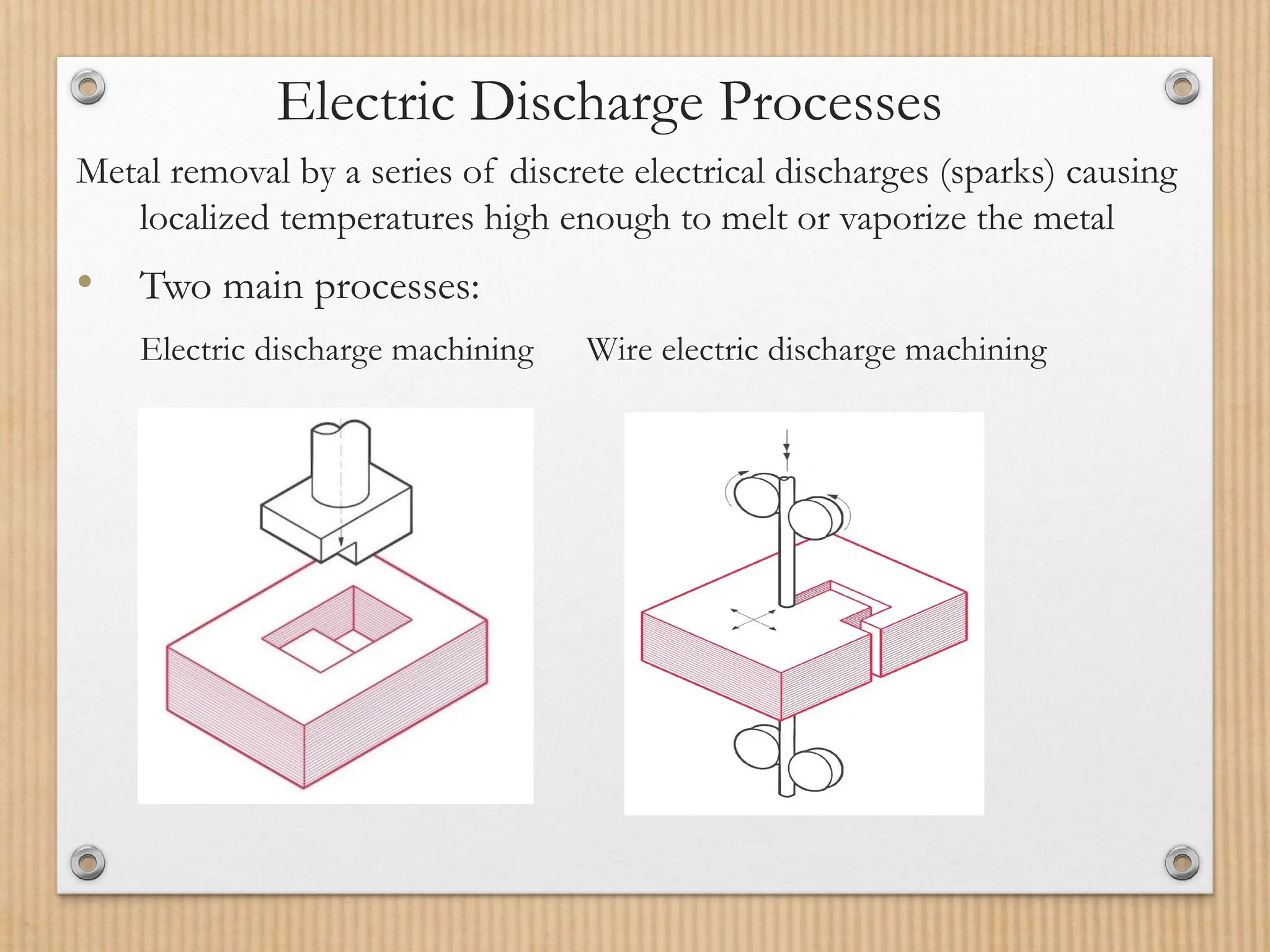
Electric Discharge Processes
Metalremoval by a series of discrete electrical discharges (sparks) causing
localized temperatures high enough to melt or vaporize the metal
• Two main processes:
Electric discharge machining Wire electric discharge machining
5.
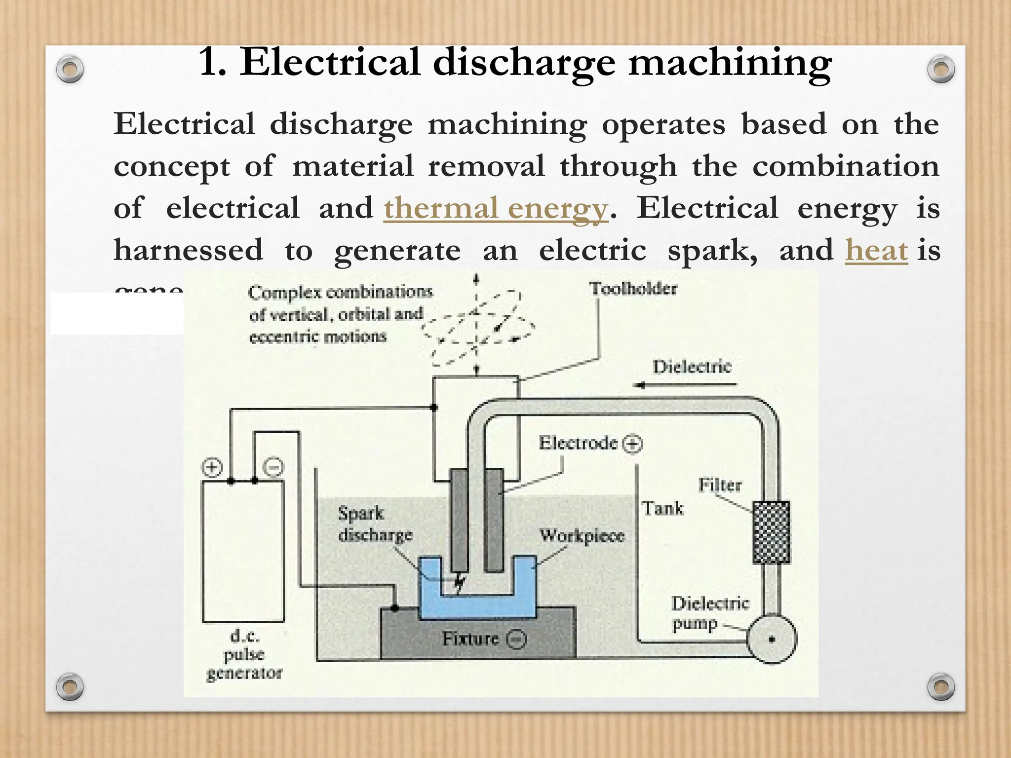
Electrical discharge machiningoperates based on the
concept of material removal through the combination
of electrical and thermal energy. Electrical energy is
harnessed to generate an electric spark, and heat is
generated as a result of metal erosion
1. Electrical discharge machining
6.
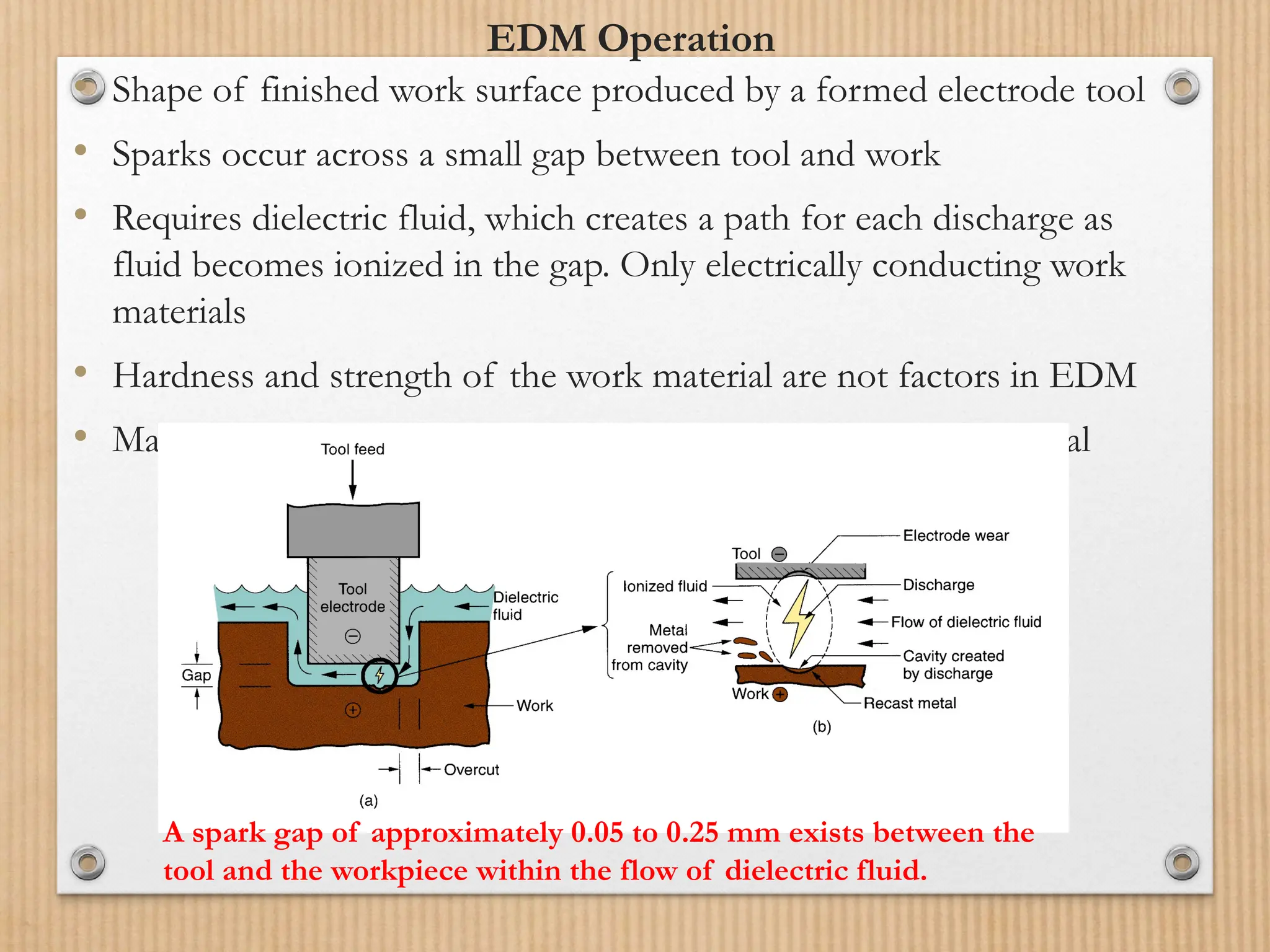
EDM Operation
• Shapeof finished work surface produced by a formed electrode tool
• Sparks occur across a small gap between tool and work
• Requires dielectric fluid, which creates a path for each discharge as
fluid becomes ionized in the gap. Only electrically conducting work
materials
• Hardness and strength of the work material are not factors in EDM
• Material removal rate is related to melting point of work material
A spark gap of approximately 0.05 to 0.25 mm exists between the
tool and the workpiece within the flow of dielectric fluid.
7.
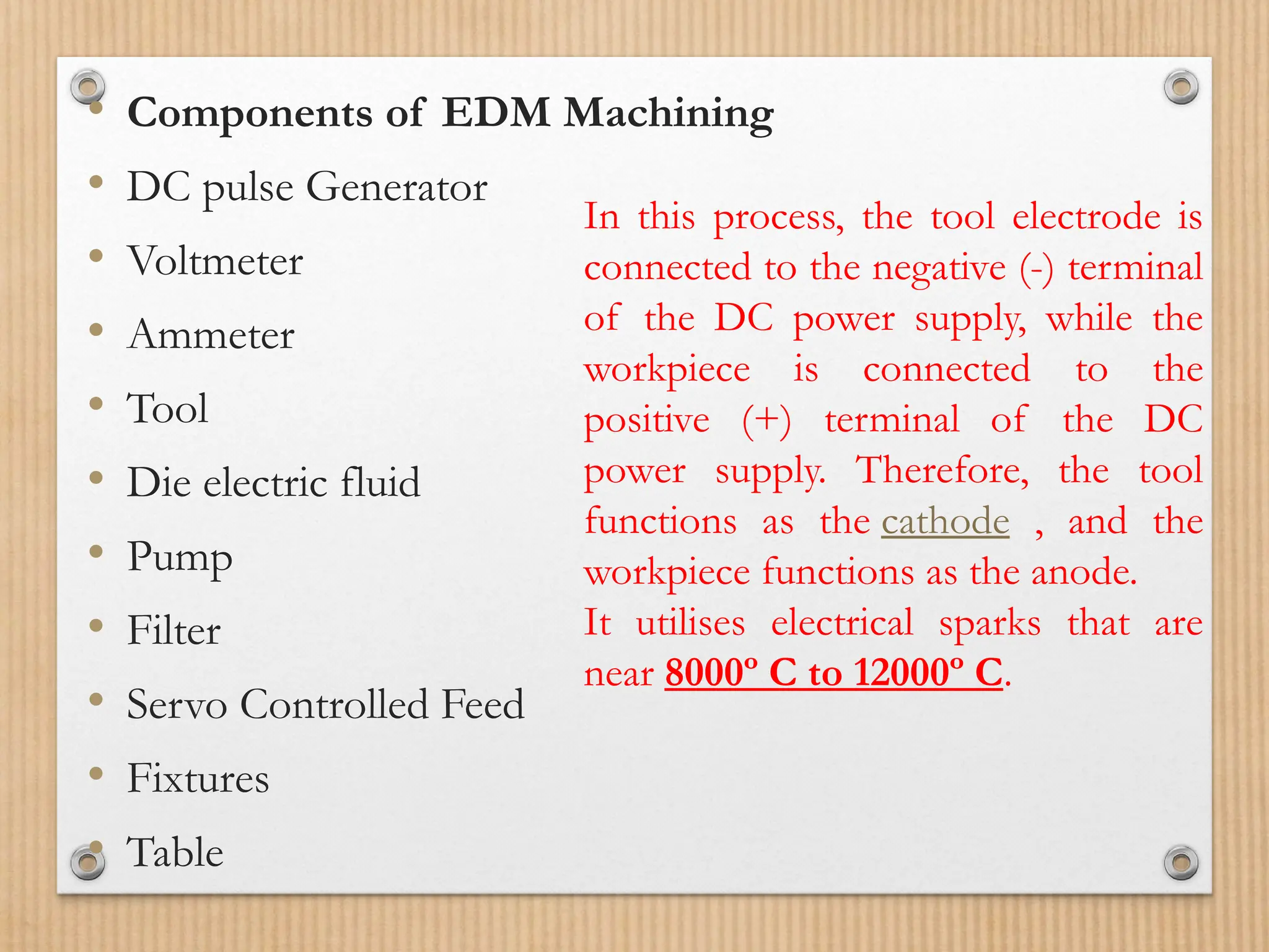
• Components ofEDM Machining
• DC pulse Generator
• Voltmeter
• Ammeter
• Tool
• Die electric fluid
• Pump
• Filter
• Servo Controlled Feed
• Fixtures
• Table
In this process, the tool electrode is
connected to the negative (-) terminal
of the DC power supply, while the
workpiece is connected to the
positive (+) terminal of the DC
power supply. Therefore, the tool
functions as the cathode , and the
workpiece functions as the anode.
It utilises electrical sparks that are
near 8000º C to 12000º C.
8.
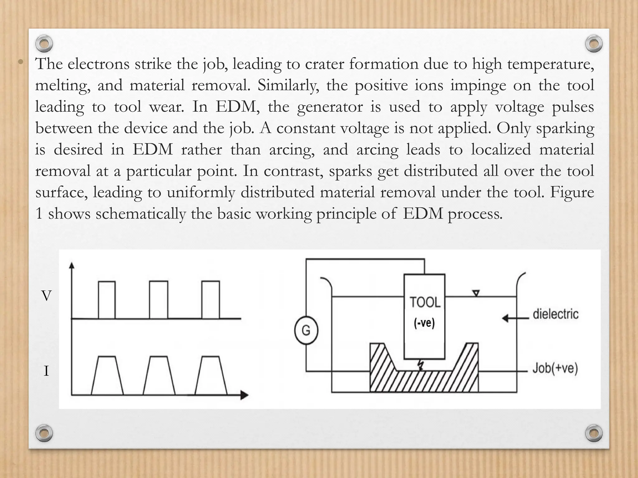
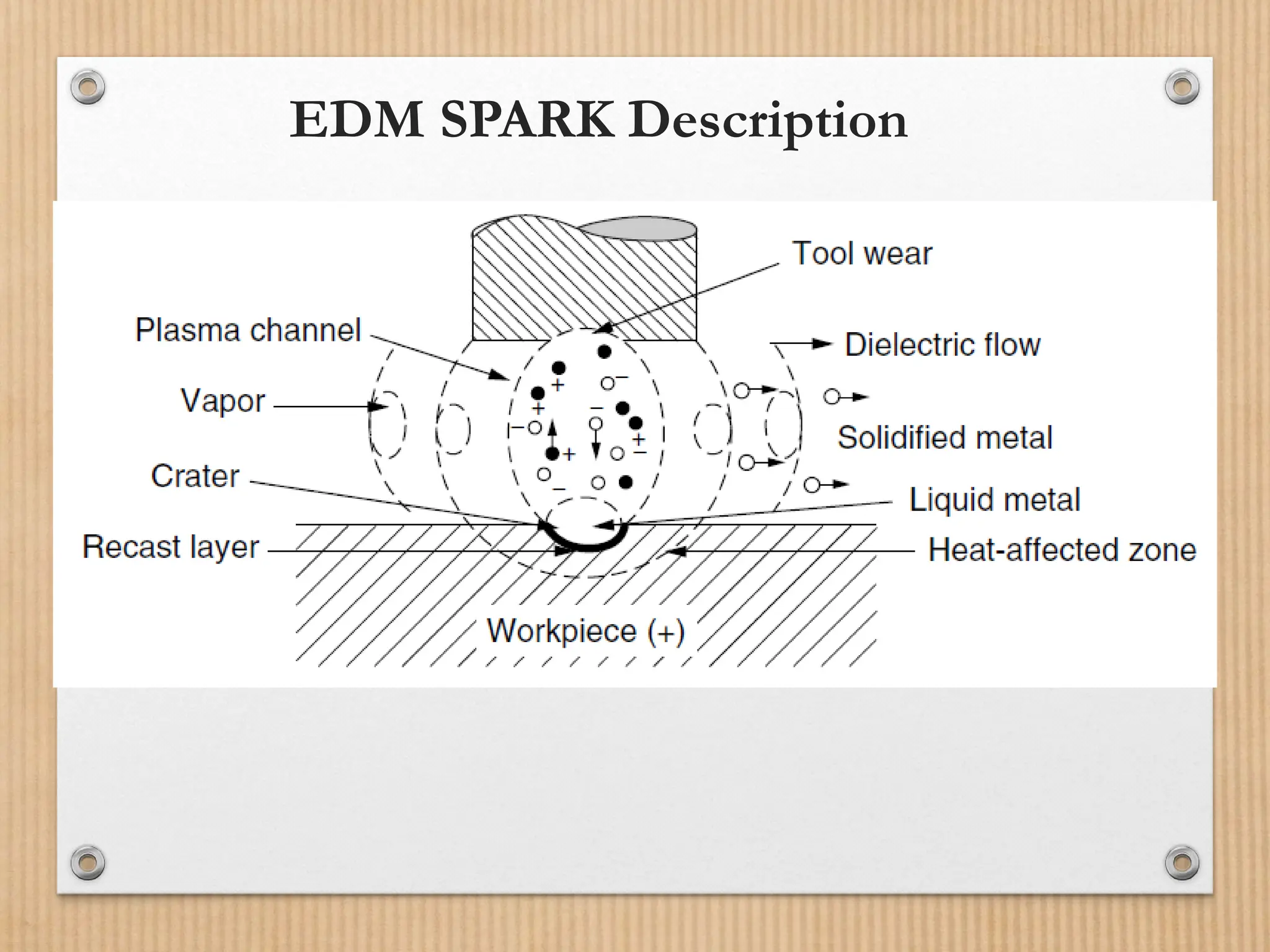
• The electronsstrike the job, leading to crater formation due to high temperature,
melting, and material removal. Similarly, the positive ions impinge on the tool
leading to tool wear. In EDM, the generator is used to apply voltage pulses
between the device and the job. A constant voltage is not applied. Only sparking
is desired in EDM rather than arcing, and arcing leads to localized material
removal at a particular point. In contrast, sparks get distributed all over the tool
surface, leading to uniformly distributed material removal under the tool. Figure
1 shows schematically the basic working principle of EDM process.
V
I
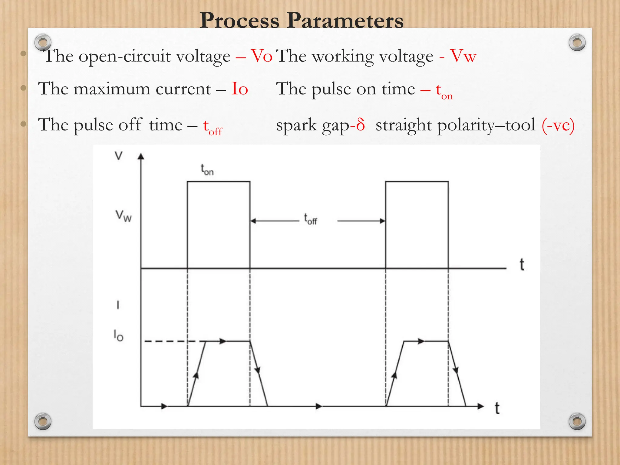
Process Parameters
• Theopen-circuit voltage – Vo The working voltage - Vw
• The maximum current – Io The pulse on time – ton
• The pulse off time – toff spark gap-δ straight polarity–tool (-ve)
11.
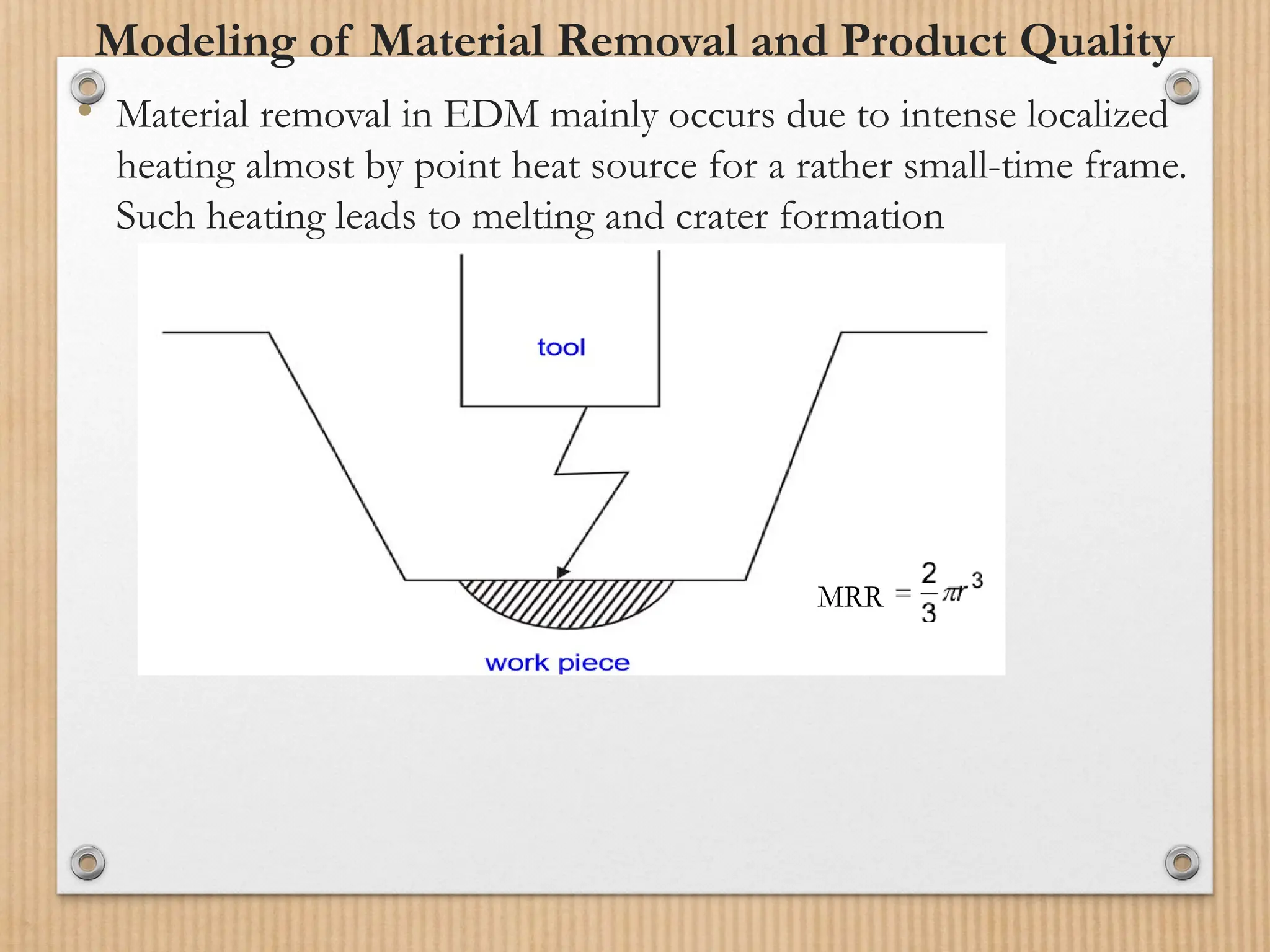
Modeling of MaterialRemoval and Product Quality
• Material removal in EDM mainly occurs due to intense localized
heating almost by point heat source for a rather small-time frame.
Such heating leads to melting and crater formation
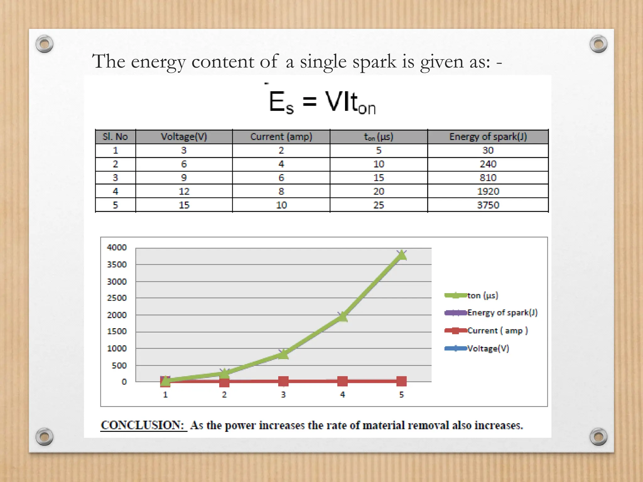
MRR
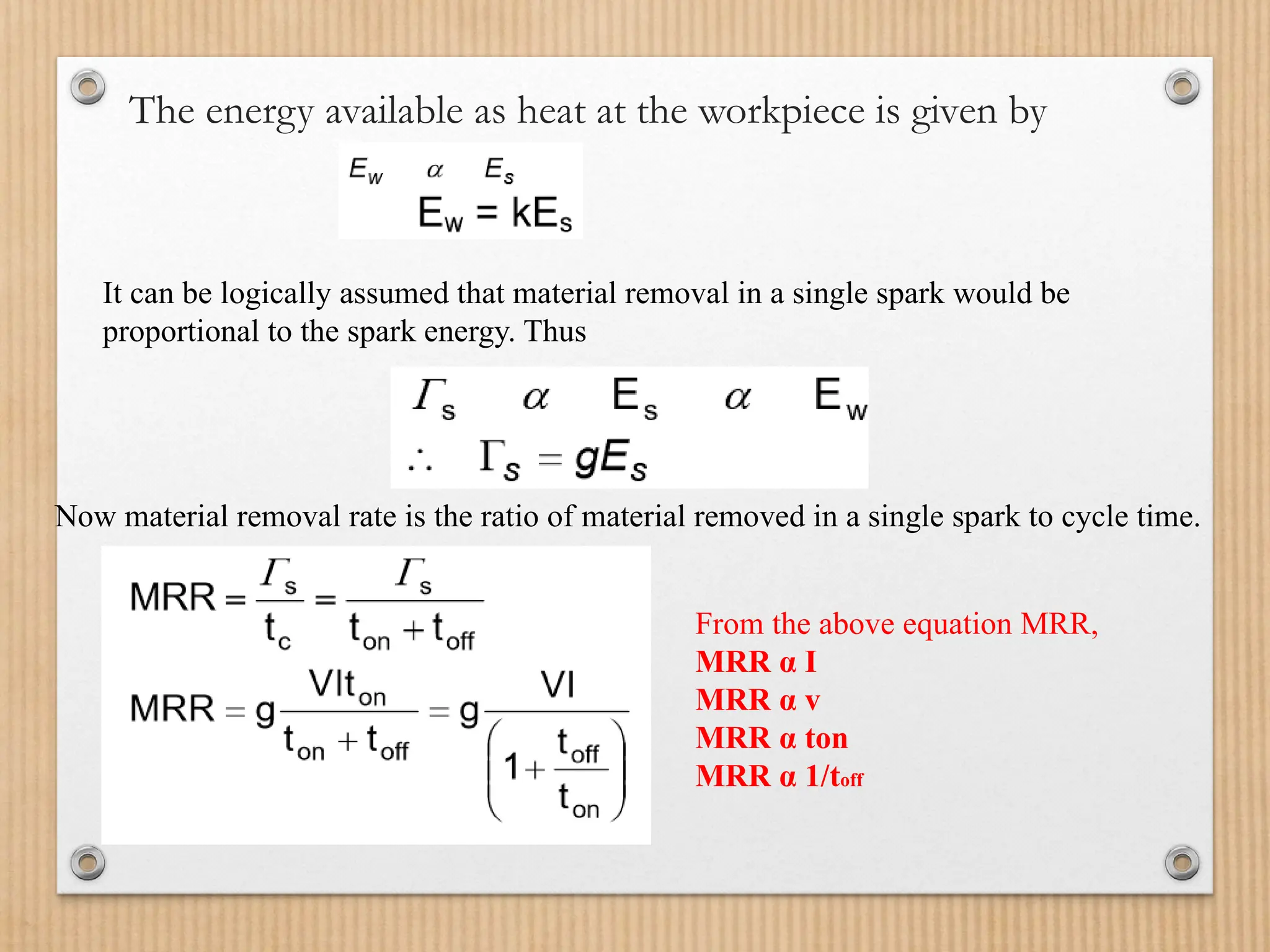
The energy availableas heat at the workpiece is given by
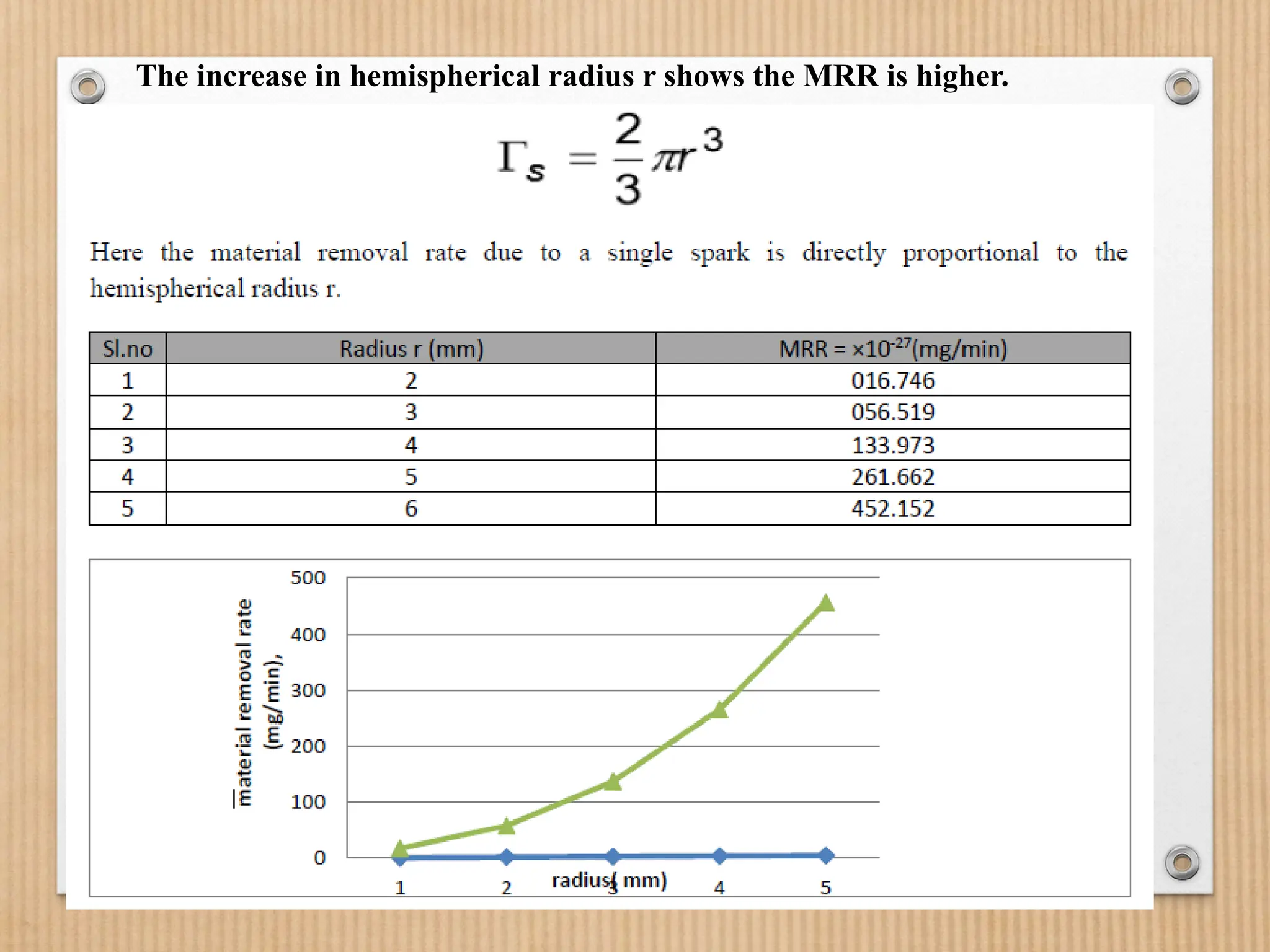
It can be logically assumed that material removal in a single spark would be
proportional to the spark energy. Thus
Now material removal rate is the ratio of material removed in a single spark to cycle time.
From the above equation MRR,
MRR α I
MRR α v
MRR α ton
MRR α 1/toff
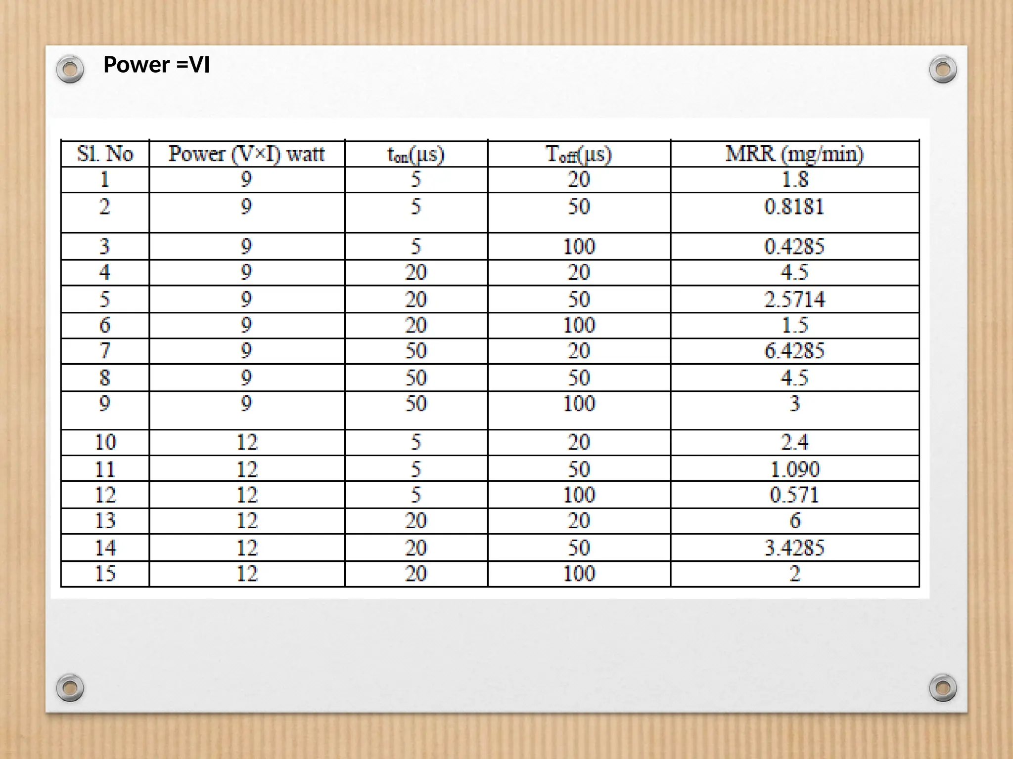
The model presentedin the table is a very simplified one, and a linear
relationship is not observed in practice. But even then, such a simplified
model captures the complexity of EDM in a very efficient manner.
MRR in practice increases with an increase in working voltage, current,
pulse on time, and decreases in pulse off time. Product quality is an
essential characteristic of a manufacturing process along with MRR.
The followings are the product quality issues in EDM: -
• Surface finish
• Overcut
• Taper cut
No two sparks take place side by side. They occur randomly so that over
time one gets uniform average material removal over the whole tool
cross-section.
17.
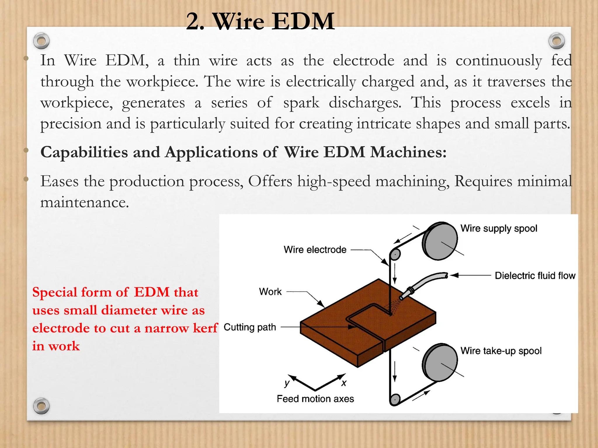
• In WireEDM, a thin wire acts as the electrode and is continuously fed
through the workpiece. The wire is electrically charged and, as it traverses the
workpiece, generates a series of spark discharges. This process excels in
precision and is particularly suited for creating intricate shapes and small parts.
• Capabilities and Applications of Wire EDM Machines:
• Eases the production process, Offers high-speed machining, Requires minimal
maintenance.
Special form of EDM that
uses small diameter wire as
electrode to cut a narrow kerf
in work
2. Wire EDM
19.
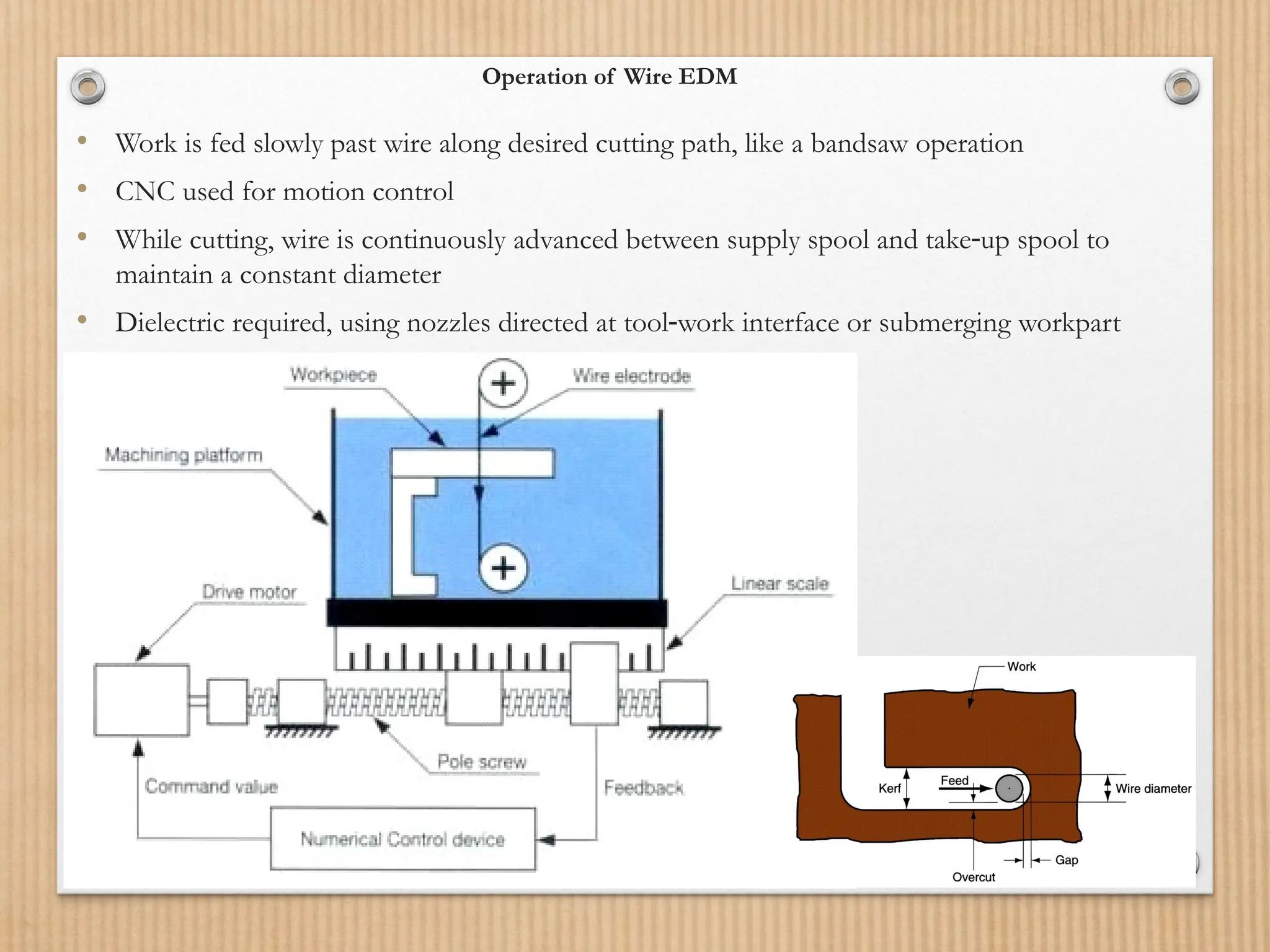
Operation of WireEDM
• Work is fed slowly past wire along desired cutting path, like a bandsaw operation
• CNC used for motion control
• While cutting, wire is continuously advanced between supply spool and take up spool to
‑
maintain a constant diameter
• Dielectric required, using nozzles directed at tool work interface or submerging workpart
‑
21.
Parameters are usedfor programming
• Wire speed: Wire speed (mm/s) = Cutting rate (mm/min) / (60 x
Thickness of the material being cut (mm))
• Current: Current (Amps) = ((Wire diameter (mm) x Material density
(g/cm3) x Cutting rate (mm/min)) / (1.85 x Pulse duration (µs))) ^0.5
• Pulse duration: Pulse duration (µs) = 0.2 x (Wire diameter (mm) /
Material resistivity (µΩ.cm))
• Spark gap: Spark gap (µm) = ((Wire diameter (mm) x Material density
(g/cm3) x Current (Amps)) / (0.7 x Cutting rate (mm/min))) ^0.5
for cutting a particular material to achieve the desired precision,
accuracy, and surface finish.
22.
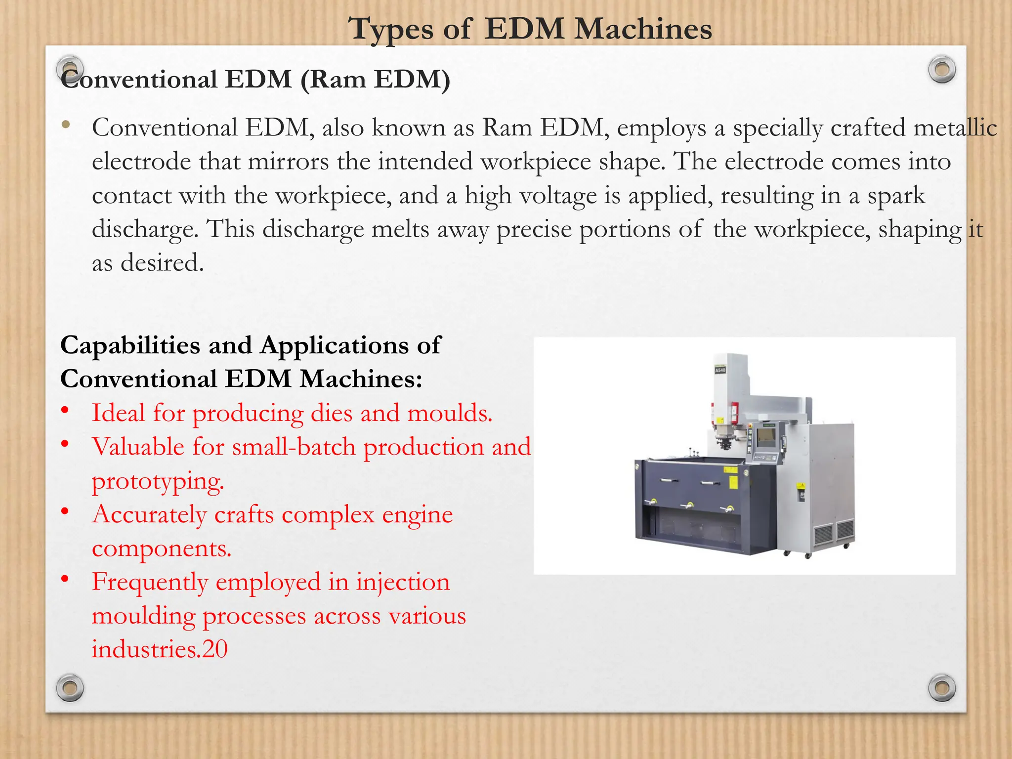
Types of EDMMachines
Conventional EDM (Ram EDM)
• Conventional EDM, also known as Ram EDM, employs a specially crafted metallic
electrode that mirrors the intended workpiece shape. The electrode comes into
contact with the workpiece, and a high voltage is applied, resulting in a spark
discharge. This discharge melts away precise portions of the workpiece, shaping it
as desired.
Capabilities and Applications of
Conventional EDM Machines:
• Ideal for producing dies and moulds.
• Valuable for small-batch production and
prototyping.
• Accurately crafts complex engine
components.
• Frequently employed in injection
moulding processes across various
industries.20
23.
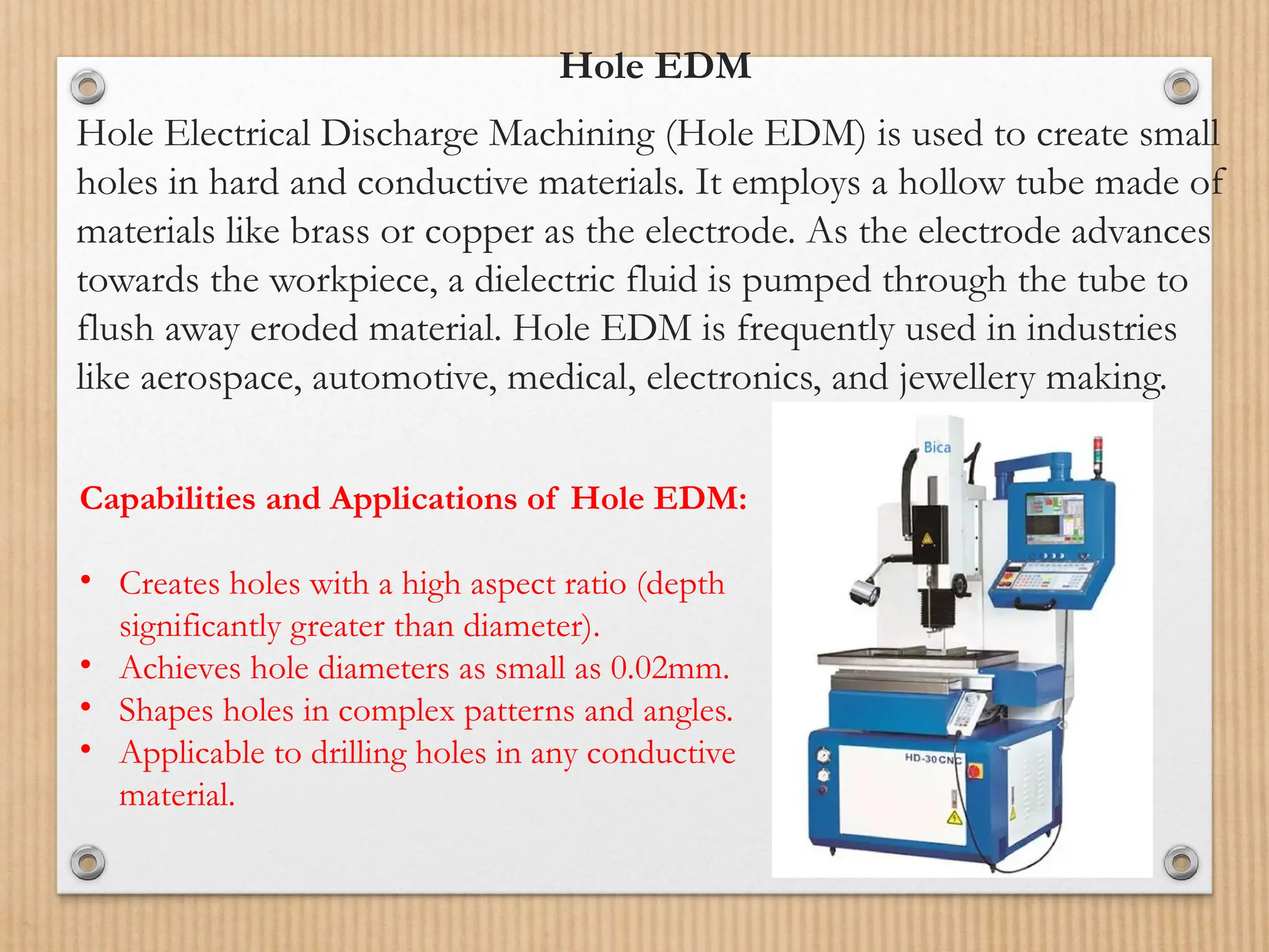
Hole EDM
Hole ElectricalDischarge Machining (Hole EDM) is used to create small
holes in hard and conductive materials. It employs a hollow tube made of
materials like brass or copper as the electrode. As the electrode advances
towards the workpiece, a dielectric fluid is pumped through the tube to
flush away eroded material. Hole EDM is frequently used in industries
like aerospace, automotive, medical, electronics, and jewellery making.
Capabilities and Applications of Hole EDM:
• Creates holes with a high aspect ratio (depth
significantly greater than diameter).
• Achieves hole diameters as small as 0.02mm.
• Shapes holes in complex patterns and angles.
• Applicable to drilling holes in any conductive
material.
24.
• Advantages ofElectrical Discharge Machining
• High Precision
• Material Versatility
• Burr-Free Finishes
• Complex Geometries
• Hardened Materials
• No Tool Wear
• Heat-Affected Zone Control
• Thin Workpieces
• Low Impact on Workpiece
25.
Disadvantages of ElectricalDischarge Machining
• Excessive tool wear.
• High power consumption.
• The sharp corner cannot be reproduced.
• High heat development causes a change in the metallurgical
properties of materials.
• The workpiece must be an electrical conductor.
• Surface cracking may take place in some materials.
• Redressing of a tool is required for deep holes.
• Over-cut is formed.
• Difficult finding expert machinists.
26.
• Applications ofElectrical Discharge Machining
• The various applications encompass the following:
• Helical profile milling.
• Curved hole drilling.
• Engraving operation on harder materials.
• Drilling for micro holes in the nozzle.
• Used in thread cutting.
• Used in wire cutting.
• Rotary form cutting.
• Cutting off operation.
27.
Types of CommonlyUsed Dielectric Fluids
• Dielectric fluids play a crucial role in the process of electrical
discharge machining (EDM) by acting as a medium for the sparks
to travel between the electrode and the workpiece. There are
several types of dielectric fluids commonly used in EDM, each
with its own set of properties and advantages. In this section, we
will explore some of the most commonly used dielectric fluids in
EDM and discuss their characteristics and applications.
• Dielectric fluid should provide an oxygen free machining environment.
• It should have enough strong dielectric resistance so that it does not
break down electrically too easily but at the same time ionize when
electrons collide with its molecule.
• During sparking it should be thermally resistant as well.
28.
Types of CommonlyUsed Dielectric Fluids
• Hydrocarbon Oil
• A synthetic solution designed to have high thermal conductivity, excellent dielectric
properties, and compatibility with different materials in electronic systems.
• Transformer Oil
Dielectric transformer oil functions as an insulator and cooler to a
transformer’s metal components. It also prevents oxidation and corrosion around
the core and windings of a transformer.
• Paraffin Oil: Paraffin is a type of hydrocarbon oil commonly used as a fuel for jet
engines and rockets, as well as a fuel or fuel component for diesel and tractor
engines. Paraffin oil has a high viscosity index which is good for engine oil but bad
for transformers.
• Kerosene: Kerosene is a specific type of paraffin oil also used as a dielectric fluid.
It is a great insulator that is used as a cheaper alternative to clear out the debris
during the erosion process in EDM.
29.
• Dielectric Gas(Sulphur Hexafluoride): Also known as an
insulating gas or sulphur hexafluoride, dielectric gas is a material
in a gaseous state that prevents electrical discharge. Although
this is not a liquid, it is another popular dielectric material often
used in power equipment and gas-insulated transmission lines.
• Lubricating Oil: This broad term is used for dielectric oils
designed to insulate, repel moisture, and prevent corrosion.
30.
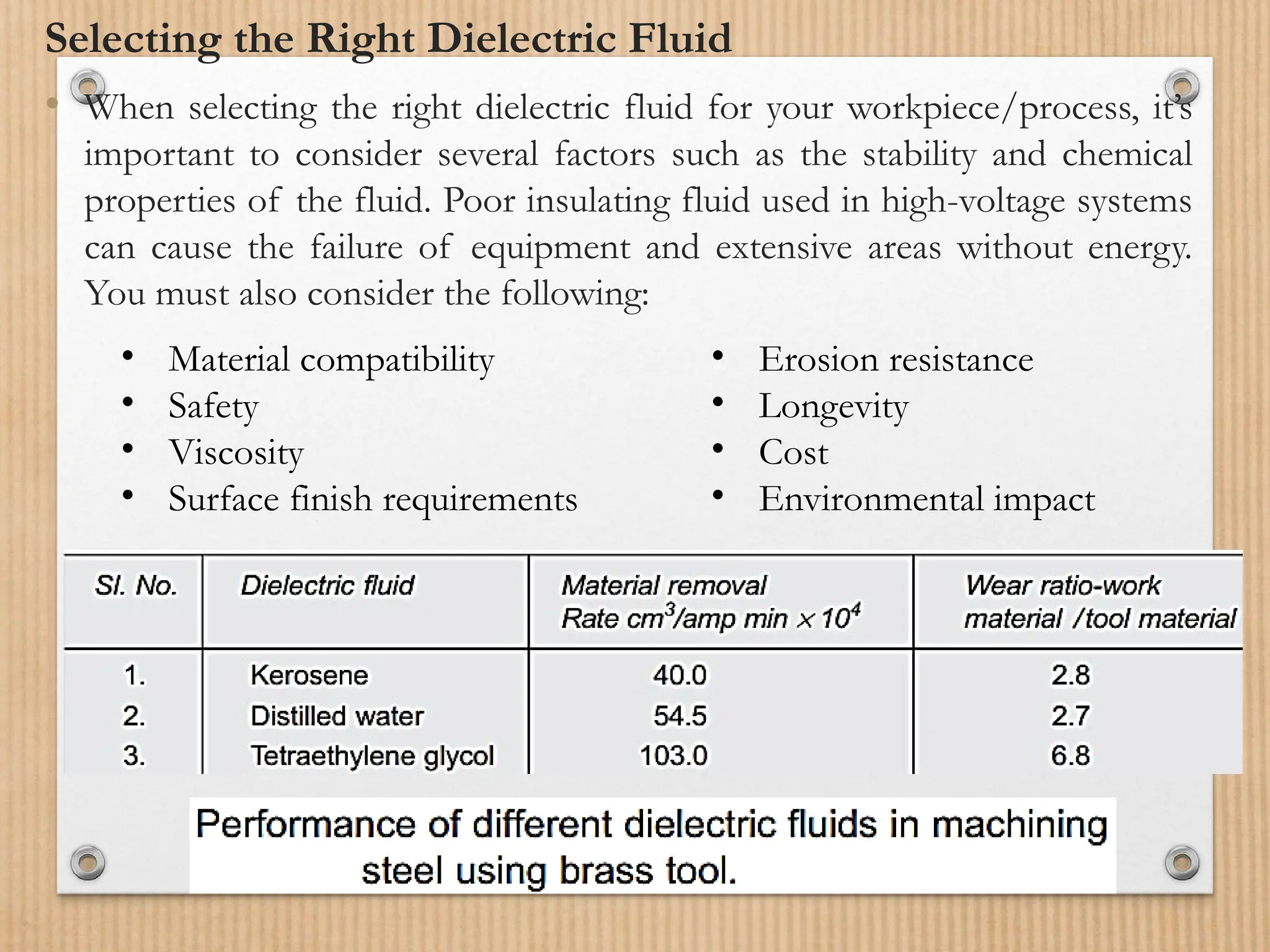
Selecting the RightDielectric Fluid
• When selecting the right dielectric fluid for your workpiece/process, it’s
important to consider several factors such as the stability and chemical
properties of the fluid. Poor insulating fluid used in high-voltage systems
can cause the failure of equipment and extensive areas without energy.
You must also consider the following:
• Material compatibility
• Safety
• Viscosity
• Surface finish requirements
• Erosion resistance
• Longevity
• Cost
• Environmental impact
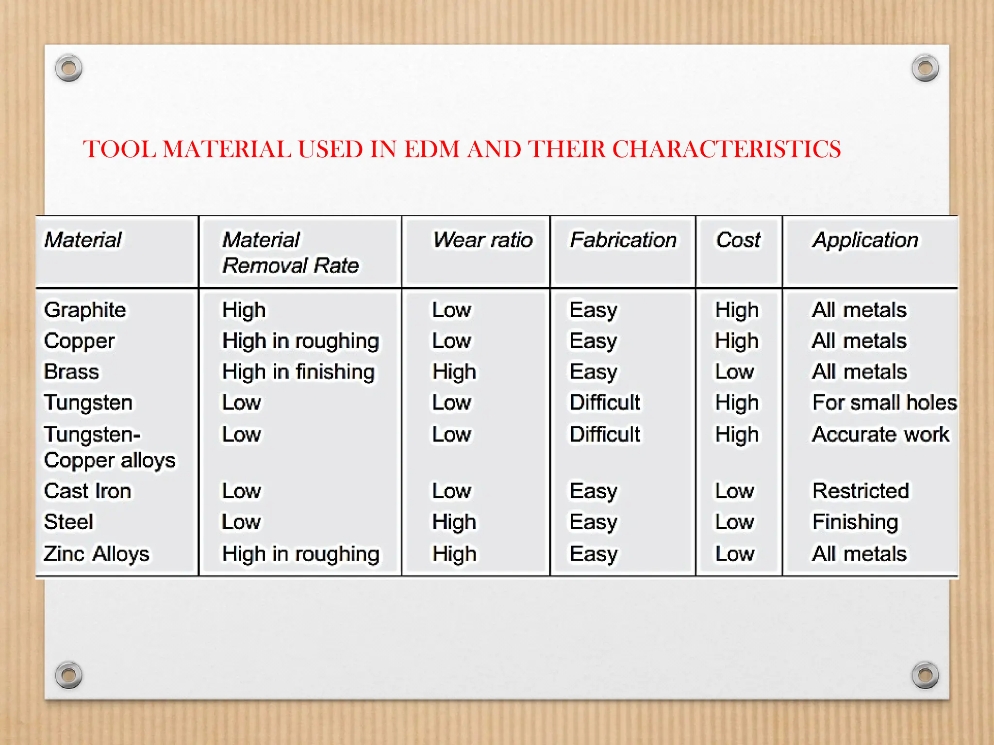
Electrode Material
The essentialcharacteristics of electrode materials are:
• High electrical conductivity
• High thermal conductivity
• Higher density
• High melting point
• Easy manufacturability
• Cost – cheap
The followings are the different electrode materials that are used
commonly in the industry:
• Graphite
• Electrolytic oxygen-free copper
• Tellurium copper – 99% Cu + 0.5% tellurium
• Brass