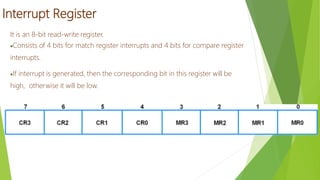
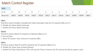
RMK COLLEGE OF ENGINEERING AND
TECHNOLOGY
DEPARTMENT OF ELECTRONICS AND
COMMUNICATION ENGINEERING
EC8791
EMBEDDED AND REAL TIME SYSTEMS
S. Rajalakshmi
AP/ECE
LPC2148 Timer Unit
Two 32 bit Timers
Designed to count cycles of the Peripheral Clock (PCLK) or an external clock
1. Prescaler Register
 32-bit register which hold the maximum value of prescale counter.
2. Prescale Counter (PC)
 32-bit, is incremented to the value stored in PR
 Increments on each tick of the PCLK. When it reaches the value in the prescaler register, the timer
count is incremented.
 Prescaler Counter (PC) is reset, on the next PCLK.
 Timer Counters increments on every PCLK when PR=0, every 2 PCLKs when PR=1, etc.
3. Timer Counter
32-bit Timer Counter which gets incremented whenever PC Prescale Counter value
reaches to its maximum value as specified in PR
4. Timer Control Register
Used to control the timer control functions
Timer Counter (TC) can be enable, disable and reset through this register
5. Count Control Register
Selects Timer Counter Mode.
6. Interrupt Register
To identify which of 6(4-match, 2-Capture) possible interrupt sources are pending.
7. Match Registers
 Match register values are continuously compared to the Timer Counter
value. When the two values are equal, actions can be triggered
automatically.
 The action possibilities are to generate an interrupt, reset the Timer
Counter, or stop the timer.
 Actions are controlled by the settings in the MCR register.
8. Match Control Register
Used to control the resetting of TC and generating of interrupt whenever a
Match occurs.
Interrupt Register
It is an 8-bit read-write register.
Consists of 4 bits for match register interrupts and 4 bits for compare register
interrupts.
If interrupt is generated, then the corresponding bit in this register will be
high, otherwise it will be low.
Timer Control Register
Match Control Register
Ec8791 lpc2148 timer unit

Ec8791 lpc2148 timer unit

  • 1.
    RMK COLLEGE OFENGINEERING AND TECHNOLOGY DEPARTMENT OF ELECTRONICS AND COMMUNICATION ENGINEERING EC8791 EMBEDDED AND REAL TIME SYSTEMS S. Rajalakshmi AP/ECE
  • 2.
    LPC2148 Timer Unit Two32 bit Timers Designed to count cycles of the Peripheral Clock (PCLK) or an external clock 1. Prescaler Register  32-bit register which hold the maximum value of prescale counter. 2. Prescale Counter (PC)  32-bit, is incremented to the value stored in PR  Increments on each tick of the PCLK. When it reaches the value in the prescaler register, the timer count is incremented.  Prescaler Counter (PC) is reset, on the next PCLK.  Timer Counters increments on every PCLK when PR=0, every 2 PCLKs when PR=1, etc.
  • 3.
    3. Timer Counter 32-bitTimer Counter which gets incremented whenever PC Prescale Counter value reaches to its maximum value as specified in PR 4. Timer Control Register Used to control the timer control functions Timer Counter (TC) can be enable, disable and reset through this register 5. Count Control Register Selects Timer Counter Mode. 6. Interrupt Register To identify which of 6(4-match, 2-Capture) possible interrupt sources are pending.
  • 4.
    7. Match Registers Match register values are continuously compared to the Timer Counter value. When the two values are equal, actions can be triggered automatically.  The action possibilities are to generate an interrupt, reset the Timer Counter, or stop the timer.  Actions are controlled by the settings in the MCR register. 8. Match Control Register Used to control the resetting of TC and generating of interrupt whenever a Match occurs.
  • 5.
    Interrupt Register It isan 8-bit read-write register. Consists of 4 bits for match register interrupts and 4 bits for compare register interrupts. If interrupt is generated, then the corresponding bit in this register will be high, otherwise it will be low.
  • 6.
  • 7.