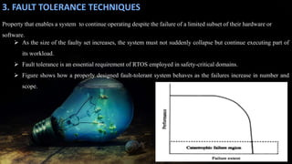
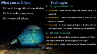
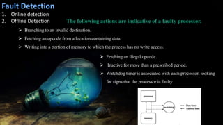
RMK COLLEGE OF ENGINEERING AND
TECHNOLOGY
DEPARTMENT OF ELECTRONICS AND COMMUNICATION ENGINEERING
Ms. S. Rajalakshmi
EMBEDDED AND REAL TIME
SYSTEM
Unit- 4
REAL TIME SYSTEMS
Structure of a Real Time
System
01
Estimating Program Run
Time
02
Task Assignment and
Scheduling
03
Fault Tolerance
Techniques
04
Reliability , Evaluation05
Clock Synchronization06
• Infographic StylePrescribed Text Books & Reference Books
TEXT BOOK
Jane W.S.Liu,‖ Real Time Systems‖, Pearson
Education, Third Indian Reprint, 2003.(UNIT IV)
REFERENCE
C.M. Krishna, Kang G. Shin, ―Real-Time Systems‖,
International Editions, Mc Graw Hill 1997
S.No Topic Online
Source
Duration
1 Mastering RTOS: Hands on Free RTOS and STM32Fx
with Debugging
Udemy 15 hours
2 Embedded Hardware and Operating Systems Coursera 4 weeks
3. FAULT TOLERANCE TECHNIQUES
 As the size of the faulty set increases, the system must not suddenly collapse but continue executing part of
its workload.
 Fault tolerance is an essential requirement of RTOS employed in safety-critical domains.
 Figure shows how a properly designed fault-tolerant system behaves as the failures increase in number and
scope.
Property that enables a system to continue operating despite the failure of a limited subset of their hardware or
software.
Types of Faults
Hardware fault Physical defect that can cause a component to malfunction. A broken wire or
the output of a logic gate that is perpetually stuck at some logic value (0 or 1) are hardware
faults.
Software fault Bug" that can cause the program to fail for a given set of inputs.
Error Recovery
Process by which the system attempts to recover from
the effects of an error
Forward error recovery Errors are masked without
any computation having to be redone
Backward error recovery system is rolled to a
moment in time before the error is believed to have
occurred.
What causes failure
Errors in the specification or design,
Defects in the components,
Environmental effects.
Fault types
1. Temporal Behavior
 Permanent - does not die away but remains until it is
repaired.
 Intermittent – due to the malfunction of a device that
occurs at intervals
 Transient – no longer present if power is disconnected
for a short time. (env effect- electromagnetic radiation
2. Output Behavior
Fail stop unit –Responds to maximum number of failures
and stops rather than producing incorrect output
Fail Safe unit – baised to single output instead of multiple
output
Fault Detection
1. Online detection
2. Offline Detection The following actions are indicative of a faulty processor.
 Branching to an invalid destination.
 Fetching an opcode from a location containing data.
 Writing into a portion of memory to which the process has no write access.
 Fetching an illegal opcode.
 Inactive for more than a prescribed period.
 Watchdog timer is associated with each processor, looking
for signs that the processor is faulty
Fault and Error Containment
1.Hardware redundancy: presence of extra hardware or
data components
2.Software redundancy: when one version of a task fails
under certain inputs, another version can be used.
3.Time redundancy: additional time that is used to deliver
the service of the system (e.g., multiple execution of the
operation)
4. Information Redundancy-Coding to detect or correct
errors. complementary information added to the original one
(e.g., checksum, parity bits, error detection, and correction
codes)
1. Containment
Fault containment zone
Error containment zone
2. Multiple Processor
Redundancy
THANK YOU

Fault tolerance techniques

  • 1.
    RMK COLLEGE OFENGINEERING AND TECHNOLOGY DEPARTMENT OF ELECTRONICS AND COMMUNICATION ENGINEERING Ms. S. Rajalakshmi EMBEDDED AND REAL TIME SYSTEM
  • 2.
    Unit- 4 REAL TIMESYSTEMS Structure of a Real Time System 01 Estimating Program Run Time 02 Task Assignment and Scheduling 03 Fault Tolerance Techniques 04 Reliability , Evaluation05 Clock Synchronization06
  • 3.
    • Infographic StylePrescribedText Books & Reference Books TEXT BOOK Jane W.S.Liu,‖ Real Time Systems‖, Pearson Education, Third Indian Reprint, 2003.(UNIT IV) REFERENCE C.M. Krishna, Kang G. Shin, ―Real-Time Systems‖, International Editions, Mc Graw Hill 1997
  • 4.
    S.No Topic Online Source Duration 1Mastering RTOS: Hands on Free RTOS and STM32Fx with Debugging Udemy 15 hours 2 Embedded Hardware and Operating Systems Coursera 4 weeks
  • 5.
    3. FAULT TOLERANCETECHNIQUES  As the size of the faulty set increases, the system must not suddenly collapse but continue executing part of its workload.  Fault tolerance is an essential requirement of RTOS employed in safety-critical domains.  Figure shows how a properly designed fault-tolerant system behaves as the failures increase in number and scope. Property that enables a system to continue operating despite the failure of a limited subset of their hardware or software.
  • 6.
    Types of Faults Hardwarefault Physical defect that can cause a component to malfunction. A broken wire or the output of a logic gate that is perpetually stuck at some logic value (0 or 1) are hardware faults. Software fault Bug" that can cause the program to fail for a given set of inputs. Error Recovery Process by which the system attempts to recover from the effects of an error Forward error recovery Errors are masked without any computation having to be redone Backward error recovery system is rolled to a moment in time before the error is believed to have occurred.
  • 7.
    What causes failure Errorsin the specification or design, Defects in the components, Environmental effects. Fault types 1. Temporal Behavior  Permanent - does not die away but remains until it is repaired.  Intermittent – due to the malfunction of a device that occurs at intervals  Transient – no longer present if power is disconnected for a short time. (env effect- electromagnetic radiation 2. Output Behavior Fail stop unit –Responds to maximum number of failures and stops rather than producing incorrect output Fail Safe unit – baised to single output instead of multiple output
  • 8.
    Fault Detection 1. Onlinedetection 2. Offline Detection The following actions are indicative of a faulty processor.  Branching to an invalid destination.  Fetching an opcode from a location containing data.  Writing into a portion of memory to which the process has no write access.  Fetching an illegal opcode.  Inactive for more than a prescribed period.  Watchdog timer is associated with each processor, looking for signs that the processor is faulty
  • 9.
    Fault and ErrorContainment 1.Hardware redundancy: presence of extra hardware or data components 2.Software redundancy: when one version of a task fails under certain inputs, another version can be used. 3.Time redundancy: additional time that is used to deliver the service of the system (e.g., multiple execution of the operation) 4. Information Redundancy-Coding to detect or correct errors. complementary information added to the original one (e.g., checksum, parity bits, error detection, and correction codes) 1. Containment Fault containment zone Error containment zone 2. Multiple Processor Redundancy
  • 10.