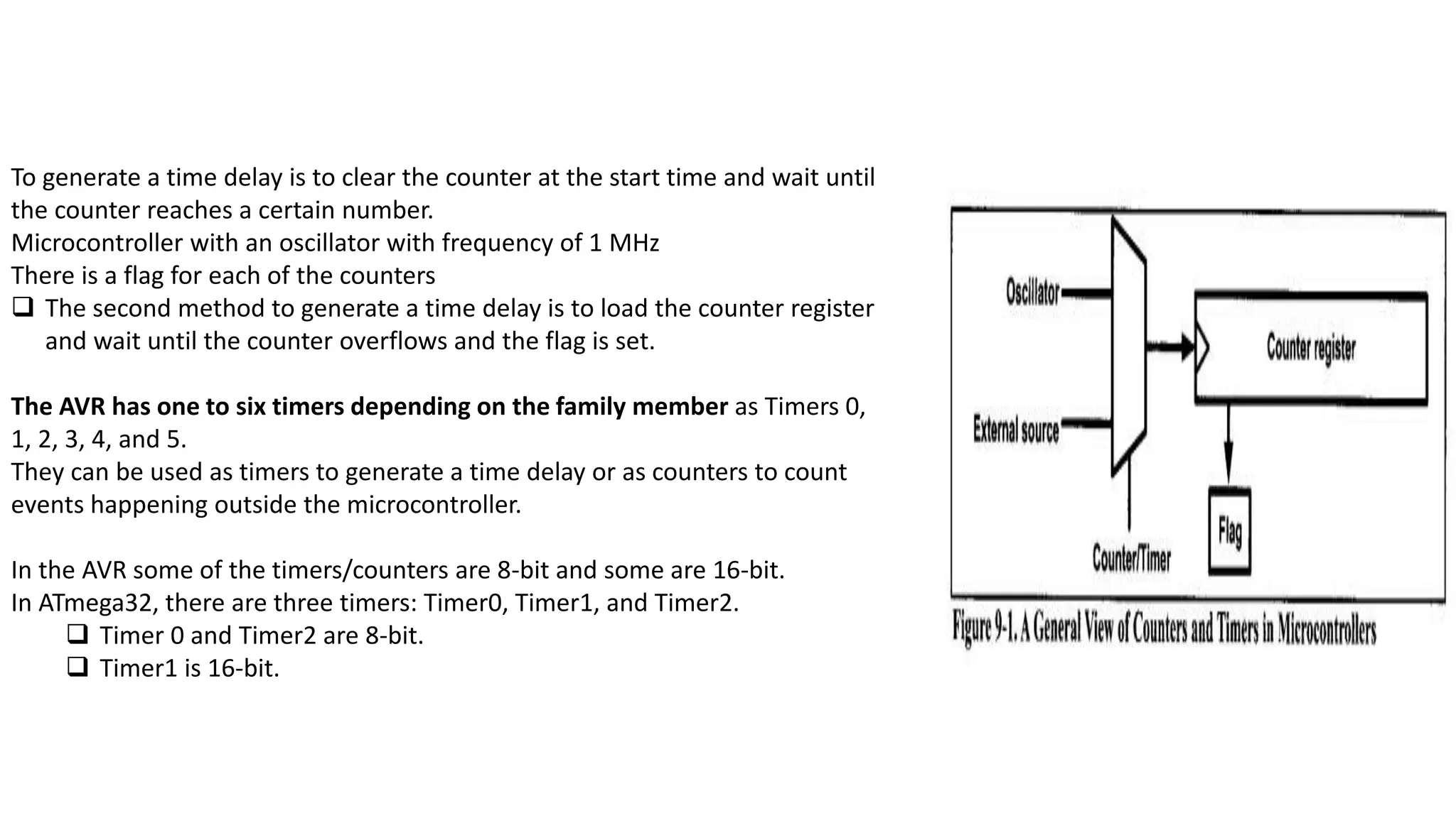
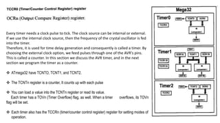
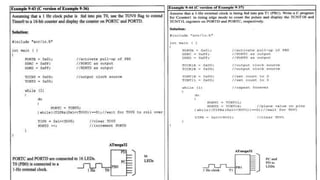
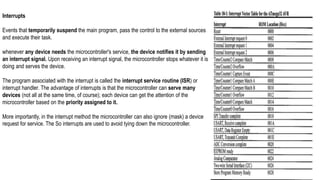
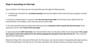
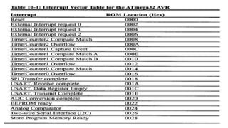
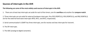
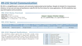
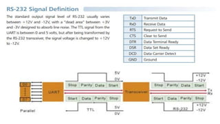
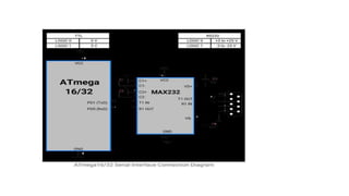
To generate a time delay is to clear the counter at the start time and wait until
the counter reaches a certain number.
Microcontroller with an oscillator with frequency of 1 MHz
There is a flag for each of the counters
 The second method to generate a time delay is to load the counter register
and wait until the counter overflows and the flag is set.
The AVR has one to six timers depending on the family member as Timers 0,
1, 2, 3, 4, and 5.
They can be used as timers to generate a time delay or as counters to count
events happening outside the microcontroller.
In the AVR some of the timers/counters are 8-bit and some are 16-bit.
In ATmega32, there are three timers: Timer0, Timer1, and Timer2.
 Timer 0 and Timer2 are 8-bit.
 Timer1 is 16-bit.
Every timer needs a clock pulse to tick. The clock source can be internal or external.
If we use the internal clock source, then the frequency of the crystal oscillator is fed
into the timer.
Therefore, it is used for time delay generation and consequently is called a timer. By
choosing the external clock option, we feed pulses through one of the AVR's pins.
This is called a counter. In this section we discuss the AVR timer, and in the next
section we program the timer as a counter.
 ATmega32 have TCNTO, TCNT1, and TCNT2.
 The TCNTn register is a counter, It counts up with each pulse
 You can load a value into the TCNTn register or read its value.
Each timer has a TOVn (Timer Overflow) flag, as well. When a timer overflows, its TOVn
flag will be set.
 Each timer also has the TCCRn (timer/counter control register) register for setting modes of
operation.
C Programming For Timers.
Interrupts
Events that temporarily suspend the main program, pass the control to the external sources
and execute their task.
whenever any device needs the microcontroller's service, the device notifies it by sending
an interrupt signal. Upon receiving an interrupt signal, the microcontroller stops whatever it is
doing and serves the device.
The program associated with the interrupt is called the interrupt service routine (ISR) or
interrupt handler. The advantage of interrupts is that the microcontroller can serve many
devices (not all at the same time, of course); each device can get the attention of the
microcontroller based on the priority assigned to it.
More importantly, in the interrupt method the microcontroller can also ignore (mask) a device
request for service. The So interrupts are used to avoid tying down the microcontroller.
Steps in executing an interrupt
Upon activation of an interrupt, the microcontroller goes through the following steps:
1. It finishes the instruction it is currently executing and saves the address of the next instruction (program counter)
on the stack.
2. It jumps to a fixed location in memory called the interrupt vector table. The interrupt vector table directs the
microcontroller to the address of the interrupt service routine (ISR).
3. The microcontroller starts to execute the interrupt service subroutine until it reaches the last instruction of the
subroutine, which is RETI (return from interrupt).
4. Upon executing the RETI instruction, the microcontroller returns to the place where it was interrupted. First, it gets
the program counter (PC) address from the stack by popping the top bytes of the stack into the PC. Then it starts to
execute from that address.
Notice from Step 4 the critical role of the stack. For this reason, we must be careful in manipulating the stack contents
in the ISR. Specifically, in the ISR, just as in any CALL subroutine, the number of pushes and pops must be equal.
Sources of interrupts in the AVR
The following are some of the most widely used sources of interrupts in the AVR:
1. There are at least two interrupts set aside for each of the timers, one for overflow and another for compare match.
2. Three interrupts are set aside for external hardware interrupts. Pins PD2 (PORTD.2), PD3 (PORTD.3), and PB2 (PORTB.2)
are for the external hard ware interrupts INTO, INT1, and INT2, respectively.
3. Serial communication's USART has three interrupts, one for receive and two interrupts for transmit.
4. The SPI interrupts.
5. The ADC (analog-to-digital converter).
RS-232 is a straightforward, universal, and commonly implemented serial interface. Despite its limited 15 m transmission
distance, its low cost and easy wiring features make RS-232 the first choice for many applications. RS-232 establishes two-
way (full-duplex) communications.
Unit 3 timer and counter and there application .pptx

Unit 3 timer and counter and there application .pptx

  • 1.
    To generate atime delay is to clear the counter at the start time and wait until the counter reaches a certain number. Microcontroller with an oscillator with frequency of 1 MHz There is a flag for each of the counters  The second method to generate a time delay is to load the counter register and wait until the counter overflows and the flag is set. The AVR has one to six timers depending on the family member as Timers 0, 1, 2, 3, 4, and 5. They can be used as timers to generate a time delay or as counters to count events happening outside the microcontroller. In the AVR some of the timers/counters are 8-bit and some are 16-bit. In ATmega32, there are three timers: Timer0, Timer1, and Timer2.  Timer 0 and Timer2 are 8-bit.  Timer1 is 16-bit.
  • 2.
    Every timer needsa clock pulse to tick. The clock source can be internal or external. If we use the internal clock source, then the frequency of the crystal oscillator is fed into the timer. Therefore, it is used for time delay generation and consequently is called a timer. By choosing the external clock option, we feed pulses through one of the AVR's pins. This is called a counter. In this section we discuss the AVR timer, and in the next section we program the timer as a counter.  ATmega32 have TCNTO, TCNT1, and TCNT2.  The TCNTn register is a counter, It counts up with each pulse  You can load a value into the TCNTn register or read its value. Each timer has a TOVn (Timer Overflow) flag, as well. When a timer overflows, its TOVn flag will be set.  Each timer also has the TCCRn (timer/counter control register) register for setting modes of operation.
  • 3.
  • 6.
    Interrupts Events that temporarilysuspend the main program, pass the control to the external sources and execute their task. whenever any device needs the microcontroller's service, the device notifies it by sending an interrupt signal. Upon receiving an interrupt signal, the microcontroller stops whatever it is doing and serves the device. The program associated with the interrupt is called the interrupt service routine (ISR) or interrupt handler. The advantage of interrupts is that the microcontroller can serve many devices (not all at the same time, of course); each device can get the attention of the microcontroller based on the priority assigned to it. More importantly, in the interrupt method the microcontroller can also ignore (mask) a device request for service. The So interrupts are used to avoid tying down the microcontroller.
  • 7.
    Steps in executingan interrupt Upon activation of an interrupt, the microcontroller goes through the following steps: 1. It finishes the instruction it is currently executing and saves the address of the next instruction (program counter) on the stack. 2. It jumps to a fixed location in memory called the interrupt vector table. The interrupt vector table directs the microcontroller to the address of the interrupt service routine (ISR). 3. The microcontroller starts to execute the interrupt service subroutine until it reaches the last instruction of the subroutine, which is RETI (return from interrupt). 4. Upon executing the RETI instruction, the microcontroller returns to the place where it was interrupted. First, it gets the program counter (PC) address from the stack by popping the top bytes of the stack into the PC. Then it starts to execute from that address. Notice from Step 4 the critical role of the stack. For this reason, we must be careful in manipulating the stack contents in the ISR. Specifically, in the ISR, just as in any CALL subroutine, the number of pushes and pops must be equal.
  • 9.
    Sources of interruptsin the AVR The following are some of the most widely used sources of interrupts in the AVR: 1. There are at least two interrupts set aside for each of the timers, one for overflow and another for compare match. 2. Three interrupts are set aside for external hardware interrupts. Pins PD2 (PORTD.2), PD3 (PORTD.3), and PB2 (PORTB.2) are for the external hard ware interrupts INTO, INT1, and INT2, respectively. 3. Serial communication's USART has three interrupts, one for receive and two interrupts for transmit. 4. The SPI interrupts. 5. The ADC (analog-to-digital converter).
  • 10.
    RS-232 is astraightforward, universal, and commonly implemented serial interface. Despite its limited 15 m transmission distance, its low cost and easy wiring features make RS-232 the first choice for many applications. RS-232 establishes two- way (full-duplex) communications.