Download as PDF, PPTX

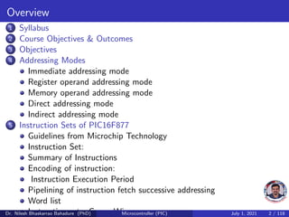

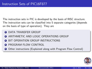
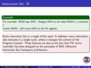
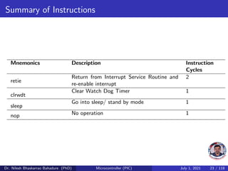
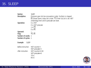
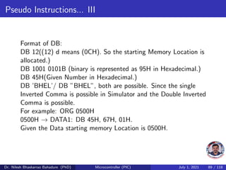
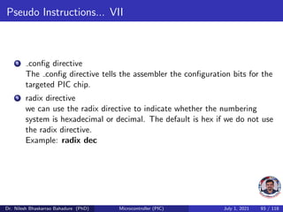
![Word list
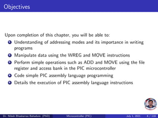
f any memory location in a microcontroller
(0x00 to 0x7F)
W work register
b bit position in ’f’ register
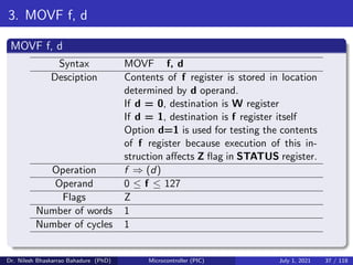
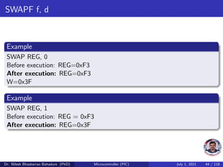
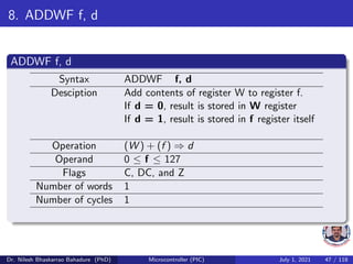
d destination bit (d=0:store result in W,
d=1:store result in file register f. Default
is d=1)
label group of eight characters which marks the
beginning of a part of the program
TOS top of stack
[] option
<> bit position inside register
Dr. Nilesh Bhaskarrao Bahadure (PhD) Microcontroller (PIC) July 1, 2021 30 / 118](https://image.slidesharecdn.com/microcontrollerpic16f877addressingmodesinstructionsandprogramming-210701072034/85/Microcontroller-pic-16f877-addressing-modes-instructions-and-programming-30-320.jpg)


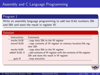


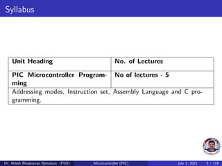
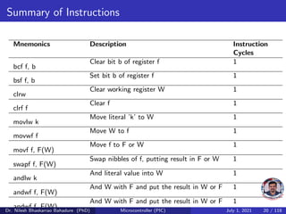
![References
[1, 2, 3, 4]
Muhammad Ali Mazidi, Rolin D. McKinlay, and Danny Causey.
PIC Microcontroller and Embedded Systems - Using Assembly and C
for PIC18.
Pearson International Edition, Upper Saddle River, NJ, 2008.
Martin P. Bates.
Programming 8 - bit PIC Microcontrollers in C with Interactive
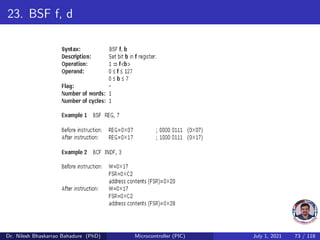
Hardware Simulation.
Newnes Press Private Limited, United Kingdom, 2008.
Ajay V. Deshmukh.
Microcontrollers Theory and Applications.
Tata McGraw Hill, New Delhi, India, 2008.
John B. Peatman.
Design with PIC Microcontroller.
Prentice Hall, New Delhi, India, 1997.
Dr. Nilesh Bhaskarrao Bahadure (PhD) Microcontroller (PIC) July 1, 2021 117 / 118](https://image.slidesharecdn.com/microcontrollerpic16f877addressingmodesinstructionsandprogramming-210701072034/85/Microcontroller-pic-16f877-addressing-modes-instructions-and-programming-117-320.jpg)
![Thank you
Please send your feedback at nbahadure@gmail.com
For download [Click Here]
Dr. Nilesh Bhaskarrao Bahadure (PhD) Microcontroller (PIC) July 1, 2021 118 / 118](https://image.slidesharecdn.com/microcontrollerpic16f877addressingmodesinstructionsandprogramming-210701072034/85/Microcontroller-pic-16f877-addressing-modes-instructions-and-programming-118-320.jpg)

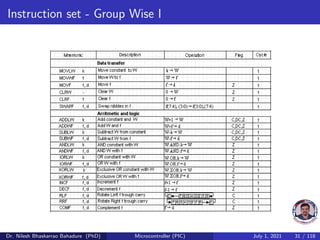
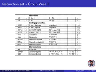
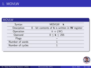
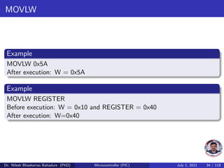
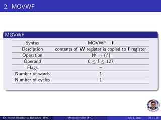
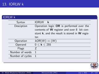
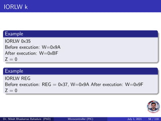
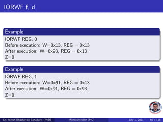
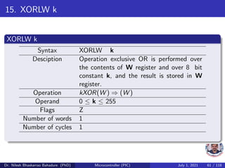
This document provides an overview and syllabus for a course on PIC microcontroller programming. It discusses the objectives of the course, which are to expose students to PIC architecture and peripherals, advanced PIC features, and assembly and C programming. The syllabus covers addressing modes, instruction sets, assembly, and C programming over 5 lectures. It also provides details on the PIC16F877 instruction set, which includes 35 instructions grouped into data transfer, arithmetic/logic, bit operations, program flow control, and other categories. Addressing modes for the PIC include immediate, register, memory, direct, and indirect.