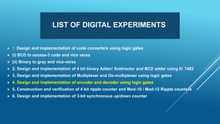
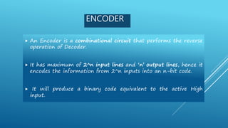
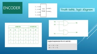
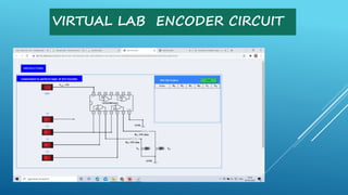
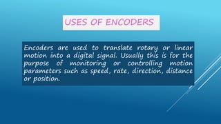
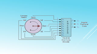
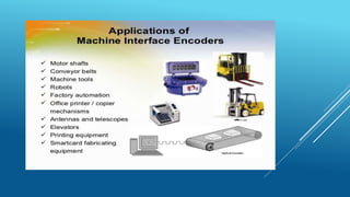
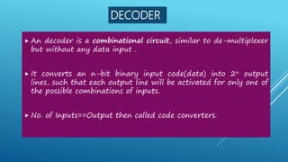
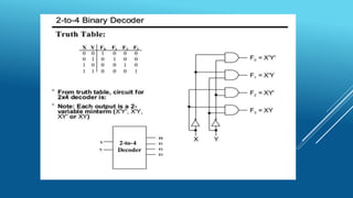
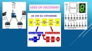
EC8361-ANALOG AND DIGITAL
CIRCUITS LABORATORY
SESSION -3
Presented by
Ms.M.Manju AP/ECE
Ms.P.Sivalakshmi AP/ECE
R.M.K COLLEGE OF ENGINEERING AND TECHNOLOGY
LIST OF DIGITAL EXPERIMENTS
 1. Design and implementation of code converters using logic gates
 (i) BCD to excess-3 code and vice versa
 (ii) Binary to gray and vice-versa
 2. Design and implementation of 4 bit binary Adder/ Subtractor and BCD adder using IC 7483
 3. Design and implementation of Multiplexer and De-multiplexer using logic gates
 4. Design and implementation of encoder and decoder using logic gates
 5. Construction and verification of 4 bit ripple counter and Mod-10 / Mod-12 Ripple counters
 6. Design and implementation of 3-bit synchronous up/down counter
ENCODER
 An Encoder is a combinational circuit that performs the reverse
operation of Decoder.
 It has maximum of 2^n input lines and ‘n’ output lines, hence it
encodes the information from 2^n inputs into an n-bit code.
 It will produce a binary code equivalent to the active High
input.
ENCODER Truth table, logic diagram
VIRTUAL LAB ENCODER CIRCUIT
USES OF ENCODERS
Encoders are used to translate rotary or linear
motion into a digital signal. Usually this is for the
purpose of monitoring or controlling motion
parameters such as speed, rate, direction, distance
or position.
DECODER
 An decoder is a combinational circuit, similar to de-multiplexer
but without any data input .
 It converts an n-bit binary input code(data) into 2n output
lines, such that each output line will be activated for only one of
the possible combinations of inputs.
 No. of Inputs==Output then called code converters.
USES OF DECODERS
DIGITAL TRAINER KIT
4-BIT RIPPLE COUNTER
4-BIT SYNCHRONOUS COUNTER
THANK YOU

Ec8361 ANALOG AND DIGITAL LABORATORY

  • 1.
    EC8361-ANALOG AND DIGITAL CIRCUITSLABORATORY SESSION -3 Presented by Ms.M.Manju AP/ECE Ms.P.Sivalakshmi AP/ECE R.M.K COLLEGE OF ENGINEERING AND TECHNOLOGY
  • 2.
    LIST OF DIGITALEXPERIMENTS  1. Design and implementation of code converters using logic gates  (i) BCD to excess-3 code and vice versa  (ii) Binary to gray and vice-versa  2. Design and implementation of 4 bit binary Adder/ Subtractor and BCD adder using IC 7483  3. Design and implementation of Multiplexer and De-multiplexer using logic gates  4. Design and implementation of encoder and decoder using logic gates  5. Construction and verification of 4 bit ripple counter and Mod-10 / Mod-12 Ripple counters  6. Design and implementation of 3-bit synchronous up/down counter
  • 3.
    ENCODER  An Encoderis a combinational circuit that performs the reverse operation of Decoder.  It has maximum of 2^n input lines and ‘n’ output lines, hence it encodes the information from 2^n inputs into an n-bit code.  It will produce a binary code equivalent to the active High input.
  • 4.
    ENCODER Truth table,logic diagram
  • 5.
  • 6.
    USES OF ENCODERS Encodersare used to translate rotary or linear motion into a digital signal. Usually this is for the purpose of monitoring or controlling motion parameters such as speed, rate, direction, distance or position.
  • 9.
    DECODER  An decoderis a combinational circuit, similar to de-multiplexer but without any data input .  It converts an n-bit binary input code(data) into 2n output lines, such that each output line will be activated for only one of the possible combinations of inputs.  No. of Inputs==Output then called code converters.
  • 11.
  • 12.
  • 13.
  • 14.
  • 15.
  • 16.
  • 18.
  • 19.