Downloaded 12 times

![SIMULINK Based Model for Determination of Different Design Parameters of a Three Phase delta
www.iosrjournals.org 32 | Page
40. Rotor slot pitch= 11.26 mm
41. Rotor tooth width= 4.467 mm
42. Rotor copper loss= 124.12 W
43. End ring current=474.8 A
44. Area of end ring= 79.13 mm²
45. Resistance of each ring = 6.322 ×10⁻⁵
ohm
46. Copper loss in end ring= 28.5 W
47. Depth of rotor core= 18 mm
48. Diameter of rotor laminations = 42.8 mm
49. Width of rotor teeth = 5.342 mm
50. Slip of the motor= 0.05753 ( ≅ 5.8 %)
XIV. CONCLUSION
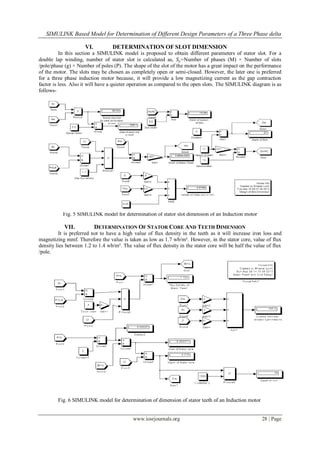
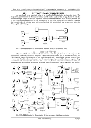
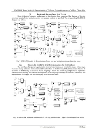
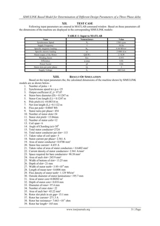
Different dimensions of the three phase induction motor are obtained from the SIMULINK diagrams.
The “slip” of the motor came out as 5.8% which is an acceptable value. In this paper, an attempt has been made
to develop a model for analysis of three phase induction motor. The developed models has been tested with the
above mentioned test specifications. Here, all possible testing were carried out on and errors are minimized for
successful operation of the software. Different examples are considered to study the performance of the
developed SIMULINK model. Test results are obtained and compared with actual result.
References
[1] I.J. Nagrath, D.P. Kothari, Electrical Machines (New Delhi, Tata McGraw-Hill Publishing company Limited, 2003)
[2] The MathWorks, Inc , Simulink- Dynamic System Simulation for Matlab (Natick, M A, USA, The MathWorks, Inc, 2000)
[3] A.K. Sawhney, A Course in Electrical Machine Design (Delhi, Dhanpat Rai & Co,2003)
[4] K.M. Vishnu Murthy, Computer-Aided Design of Electrical machines (Hyderabad, B.S. Publications, 2008)
[5] A.K. Tyagi, MATLAB and Simulink for Engineers (New Delhi, Oxford University Press, 2012)](https://image.slidesharecdn.com/e0742532-140508013341-phpapp02/85/SIMULINK-Based-Model-for-Determination-of-Different-Design-Parameters-of-a-Three-Phase-Delta-Connected-Squirrel-Cage-Induction-Motor-8-320.jpg)

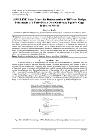
1) A SIMULINK model is presented to determine the design parameters of a 3-phase squirrel cage induction motor through computer simulation. The model calculates dimensions such as stator and rotor diameters, core lengths, slot sizes, conductor areas, and other parameters based on input specifications. 2) The document outlines the SIMULINK models used to calculate key motor components like the main frame, stator, conductor size, slots, core, air gap, rotor, end rings, and performance parameters. Test inputs are provided and the model outputs various motor dimensions that meet the specified ratings and design constraints. 3) The simulation results match expected values and indicate the motor slip will be around 5.8%, which is