Design of inductionmotor :-
The design of induction motor involves the calculation of overall
dimensions, namely the outer diameter and the axial length. This is done
with the use of the output equation. The design of the stator involves
design of winding, number of turns per phase, estimation of number of
slots, teeth, size of slots and estimation of the length of the air gap. The
design of the squirrel cage rotor involves determination of number of
rotor slots, size of rotor conductor, calculation of bar current and end
ring current. The design of slip- ring rotor includes design of rotor slots,
rotor winding design, size and shape of slots, etc. Calculation of no load
current and leakage reactance are required for determination of
efficiency.
2.
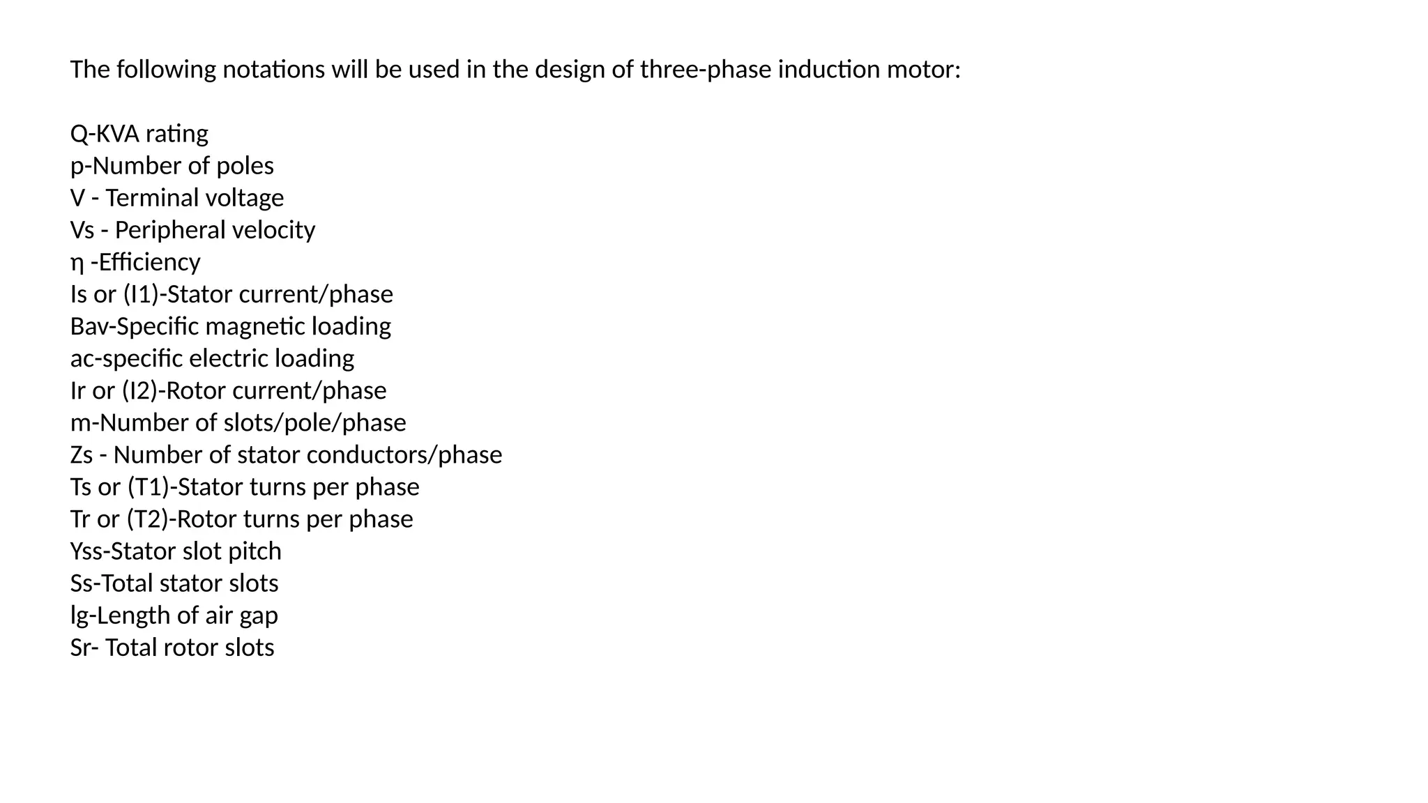
The following notationswill be used in the design of three-phase induction motor:
Q-KVA rating
p-Number of poles
V - Terminal voltage
Vs - Peripheral velocity
η -Efficiency
Is or (I1)-Stator current/phase
Bav-Specific magnetic loading
ac-specific electric loading
Ir or (I2)-Rotor current/phase
m-Number of slots/pole/phase
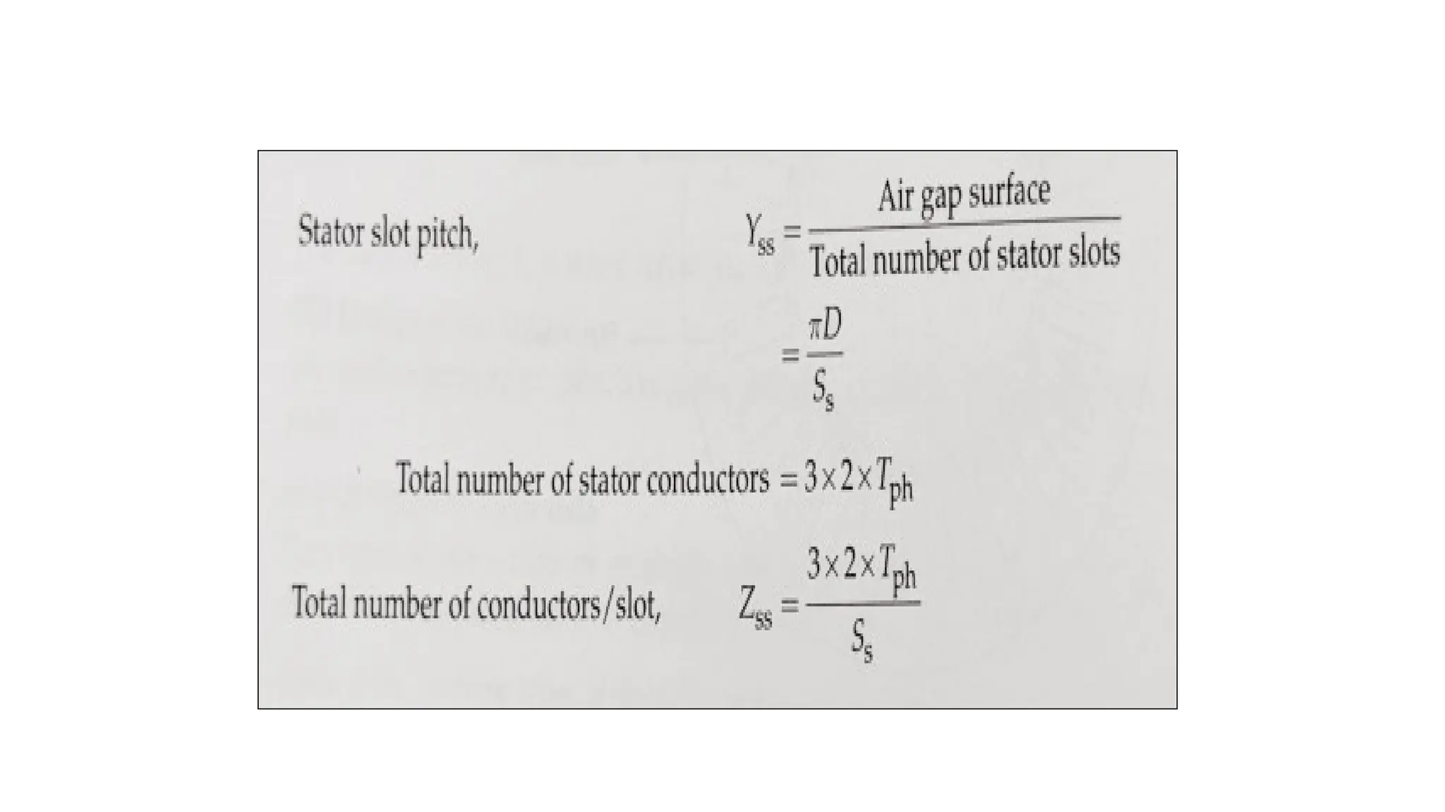
Zs - Number of stator conductors/phase
Ts or (T1)-Stator turns per phase
Tr or (T2)-Rotor turns per phase
Yss-Stator slot pitch
Ss-Total stator slots
lg-Length of air gap
Sr- Total rotor slots
3.
4.4 Output Equationof 3Φ Induction Motor :-
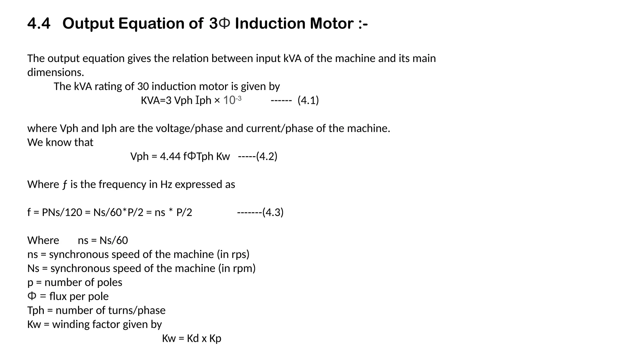
The output equation gives the relation between input kVA of the machine and its main
dimensions.
The kVA rating of 30 induction motor is given by
KVA=3 Vph Ɪph × 10-3
------ (4.1)
where Vph and Iph are the voltage/phase and current/phase of the machine.
We know that
Vph = 4.44 fΦTph Kw -----(4.2)
Where ƒ is the frequency in Hz expressed as
f = PNs/120 = Ns/60*P/2 = ns * P/2 -------(4.3)
Where ns = Ns/60
ns = synchronous speed of the machine (in rps)
Ns = synchronous speed of the machine (in rpm)
p = number of poles
Φ = flux per pole
Tph = number of turns/phase
Kw = winding factor given by
Kw = Kd x Kp
4.
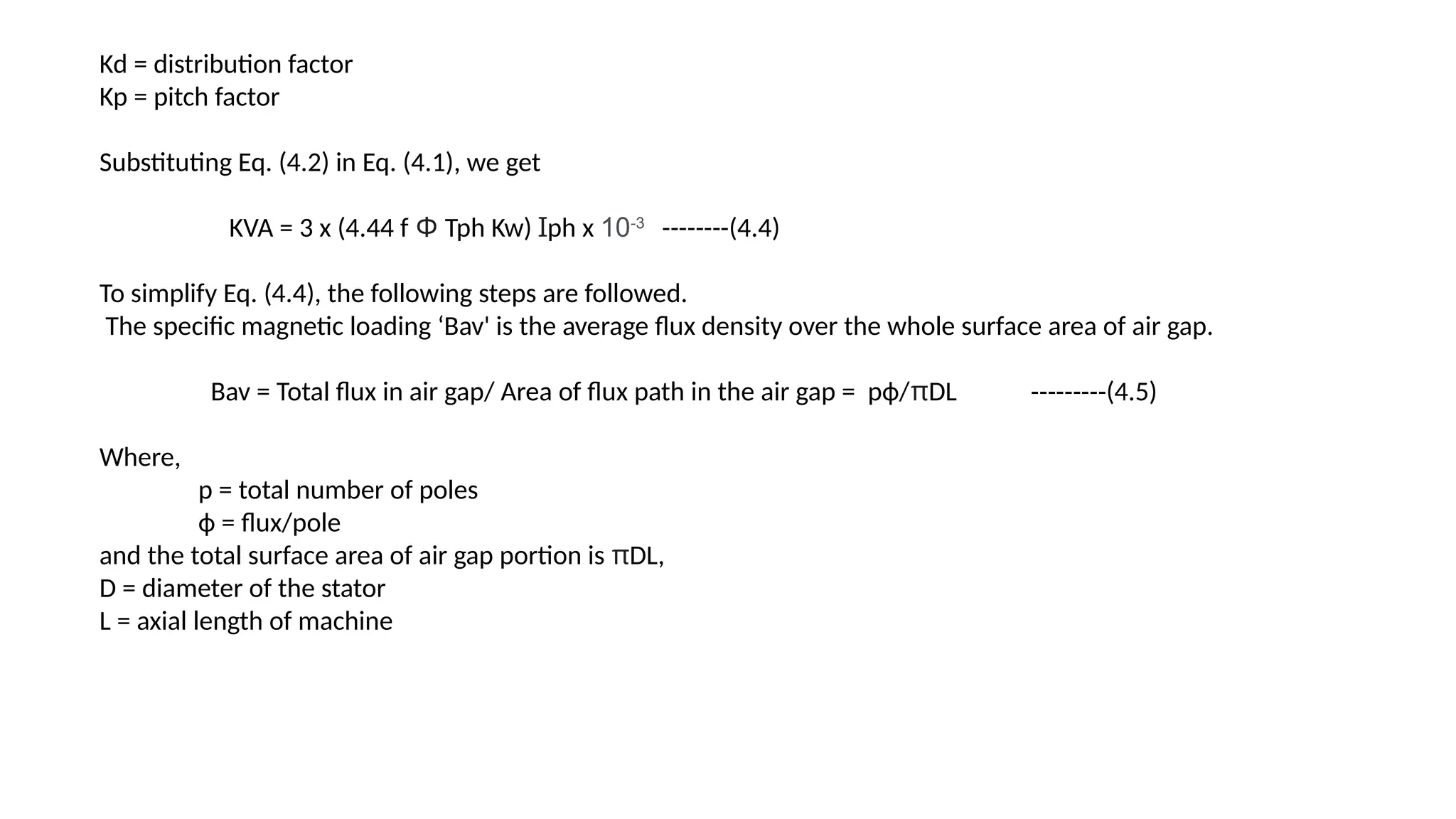
Kd = distributionfactor
Kp = pitch factor
Substituting Eq. (4.2) in Eq. (4.1), we get
KVA = 3 x (4.44 f Φ Tph Kw) Ɪph x 10-3
--------(4.4)
To simplify Eq. (4.4), the following steps are followed.
The specific magnetic loading ‘Bav' is the average flux density over the whole surface area of air gap.
Bav = Total flux in air gap/ Area of flux path in the air gap = рф/πDL ---------(4.5)
Where,
p = total number of poles
ф = flux/pole
and the total surface area of air gap portion is πDL,
D = diameter of the stator
L = axial length of machine
5.
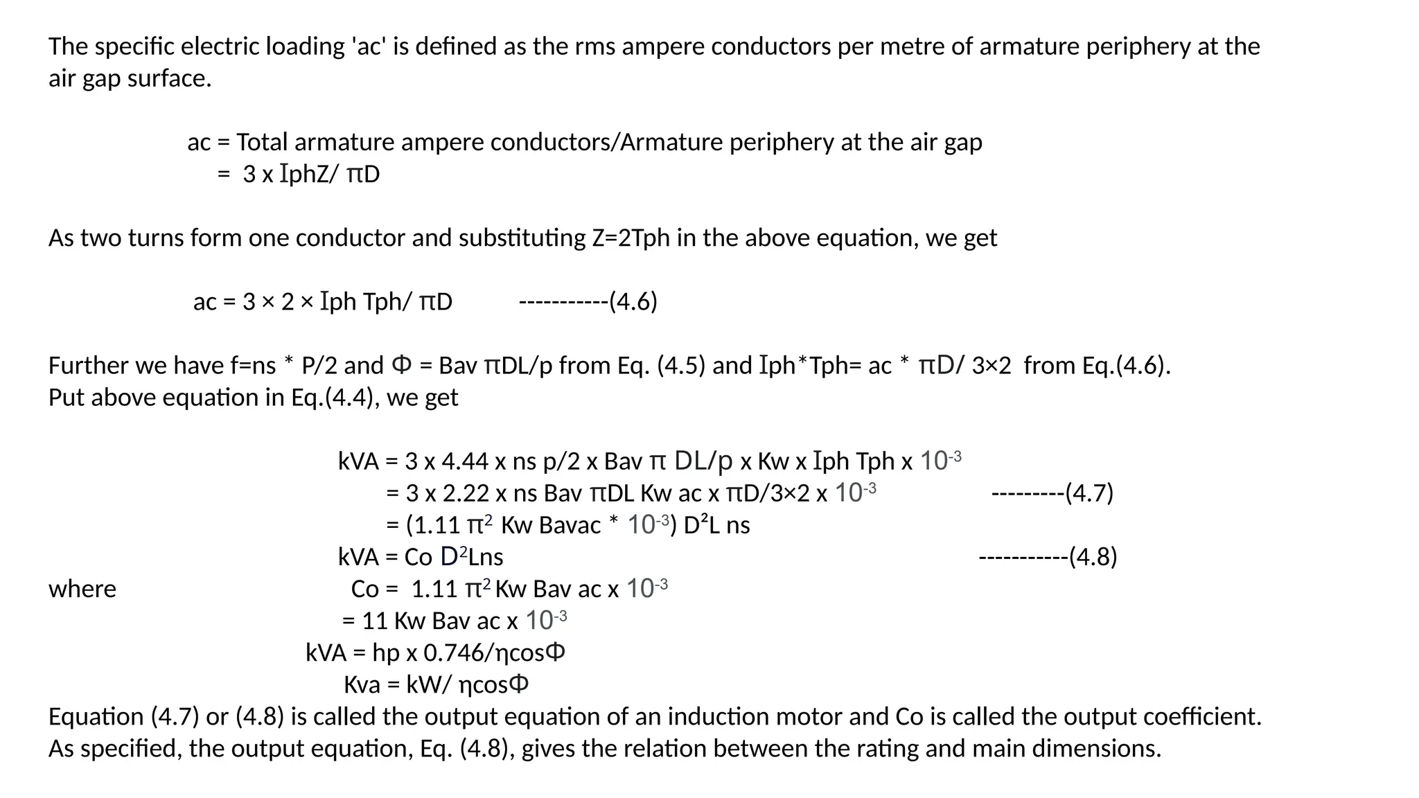
The specific electricloading 'ac' is defined as the rms ampere conductors per metre of armature periphery at the
air gap surface.
ac = Total armature ampere conductors/Armature periphery at the air gap
= 3 x ꞮphZ/ πD
As two turns form one conductor and substituting Z=2Tph in the above equation, we get
ac = 3 × 2 × Ɪph Tph/ πD -----------(4.6)
Further we have f=ns * P/2 and Φ = Bav πDL/p from Eq. (4.5) and Ɪph*Tph= ac * πD/ 3×2 from Eq.(4.6).
Put above equation in Eq.(4.4), we get
kVA = 3 x 4.44 x ns p/2 x Bav π DL/p x Kw x Ɪph Tph x 10-3
= 3 x 2.22 x ns Bav πDL Kw ac x πD/3×2 x 10-3
---------(4.7)
= (1.11 π2
Kw Bavac * 10-3
) D²L ns
kVA = Co D2
Lns -----------(4.8)
where Co = 1.11 π2
Kw Bav ac x 10-3
= 11 Kw Bav ac x 10-3
kVA = hp x 0.746/ηcosΦ
Kva = kW/ ηcosΦ
Equation (4.7) or (4.8) is called the output equation of an induction motor and Co is called the output coefficient.
As specified, the output equation, Eq. (4.8), gives the relation between the rating and main dimensions.
6.
The capacity ofmotor is usually given in HP or kW. This has to be changed into input KVA to use it in output
equation.
4.5 Choice of Specific Loadings :-
Equation (4.8) shows that for a machine of given KVA rating, volume D2
L of the machine depends on two
factors, namely the output coefficient C, and the synchronous speed in rps.
D2
L= kVA/Co*ns
The higher the values of Co and ns, the volume D2
L decreases and hence the size of the machine decreases,
Mostly, the speed ns is given as specification. Therefore, to obtain the smallest dimension of the machine, high
value of Co must be selected. But since Co is proportional to Bav and ac, we can say that the size and cost of
machine decrease if higher values of Bav and ac are used. However, the use of highest possible values of Bav
and ac will affect other important aspects like losses, efficiency, power factor, temperature rise etc.
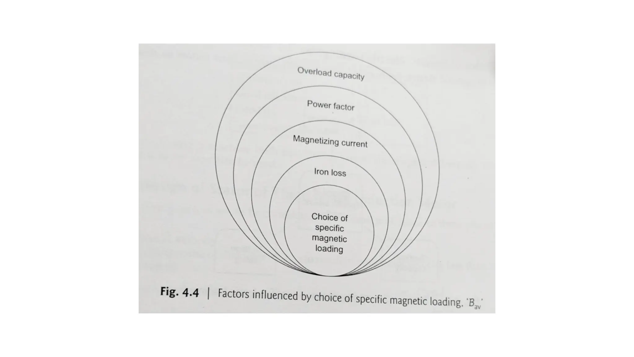
4.5.1 Choice of Specific Magnetic Loading, ‘Bav’ :-
The choice of Bay directly influences various factors as shown in Fig. 4.4.
8.
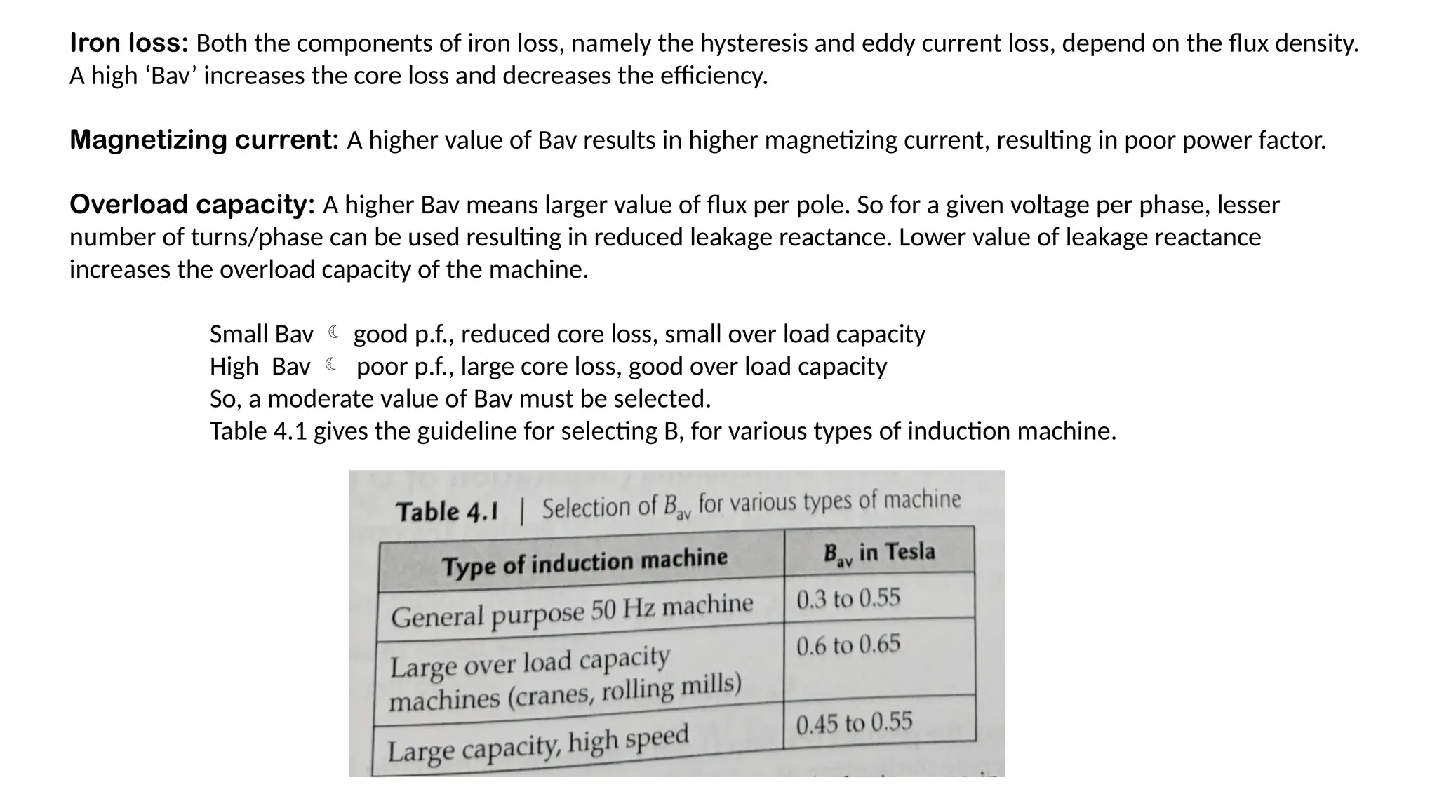
Iron loss: Boththe components of iron loss, namely the hysteresis and eddy current loss, depend on the flux density.
A high ‘Bav’ increases the core loss and decreases the efficiency.
Magnetizing current: A higher value of Bav results in higher magnetizing current, resulting in poor power factor.
Overload capacity: A higher Bav means larger value of flux per pole. So for a given voltage per phase, lesser
number of turns/phase can be used resulting in reduced leakage reactance. Lower value of leakage reactance
increases the overload capacity of the machine.
Small Bav good p.f., reduced core loss, small over load capacity
High Bav poor p.f., large core loss, good over load capacity
So, a moderate value of Bav must be selected.
Table 4.1 gives the guideline for selecting B, for various types of induction machine.
9.
It can benoted from Table 4.1 that Bav increases with the increase in the rating of the machine, just like
transformer.
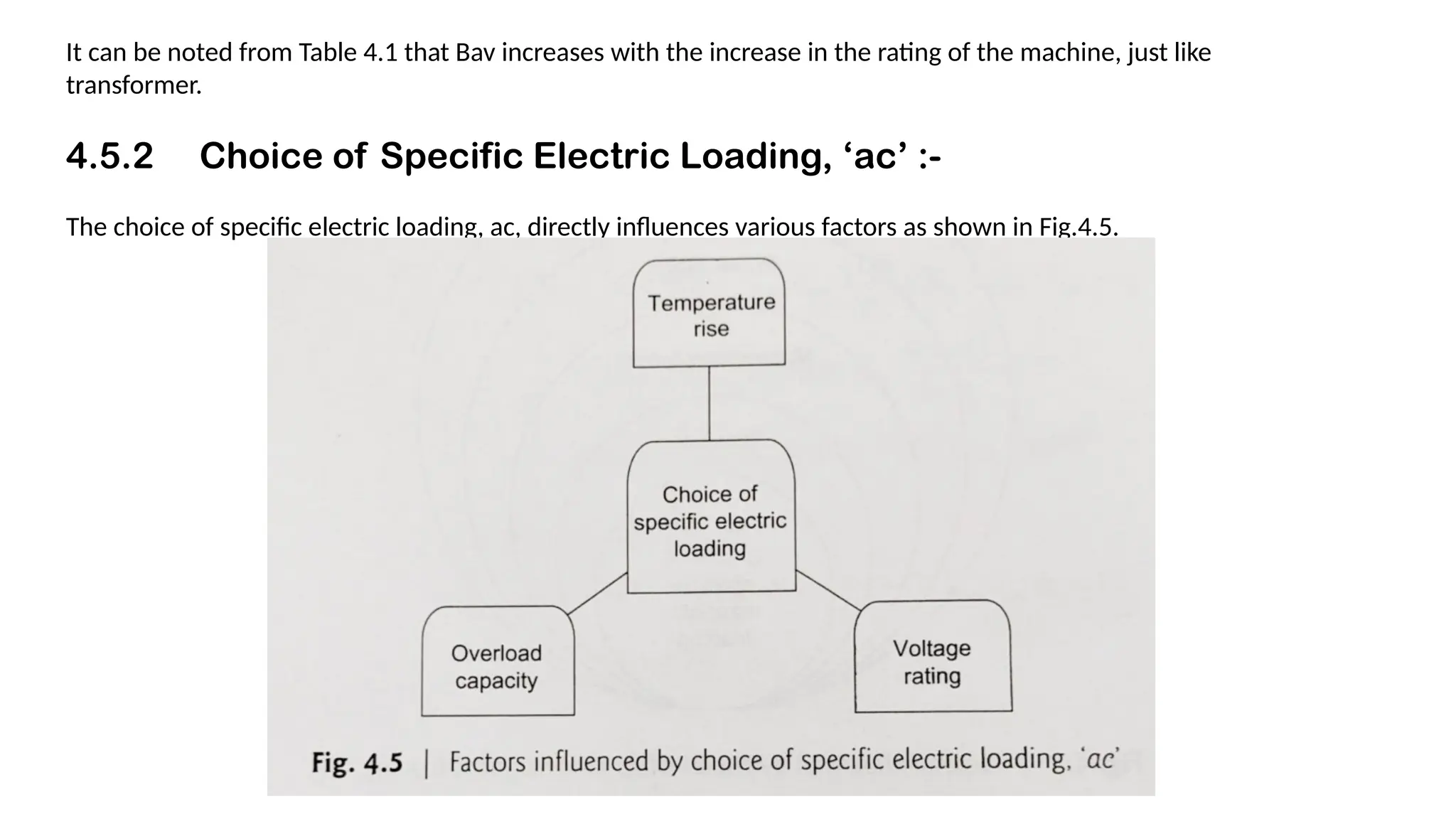
4.5.2 Choice of Specific Electric Loading, ‘ac’ :-
The choice of specific electric loading, ac, directly influences various factors as shown in Fig.4.5.
10.
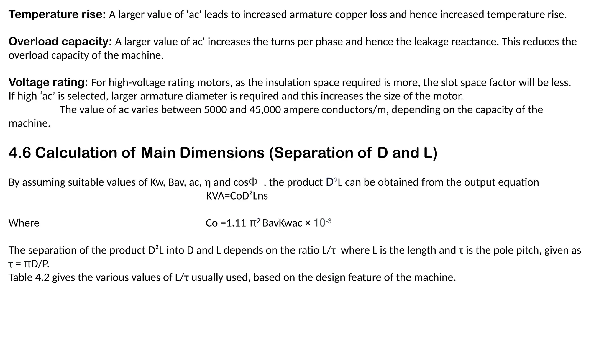
Temperature rise: Alarger value of 'ac' leads to increased armature copper loss and hence increased temperature rise.
Overload capacity: A larger value of ac' increases the turns per phase and hence the leakage reactance. This reduces the
overload capacity of the machine.
Voltage rating: For high-voltage rating motors, as the insulation space required is more, the slot space factor will be less.
If high ‘ac’ is selected, larger armature diameter is required and this increases the size of the motor.
The value of ac varies between 5000 and 45,000 ampere conductors/m, depending on the capacity of the
machine.
4.6 Calculation of Main Dimensions (Separation of D and L)
By assuming suitable values of Kw, Bav, ac, η and cosΦ , the product D2
L can be obtained from the output equation
KVA=CoD²Lns
Where Co =1.11 π2
BavKwac × 10-3
The separation of the product D²L into D and L depends on the ratio L/τ where L is the length and τ is the pole pitch, given as
τ = πD/P.
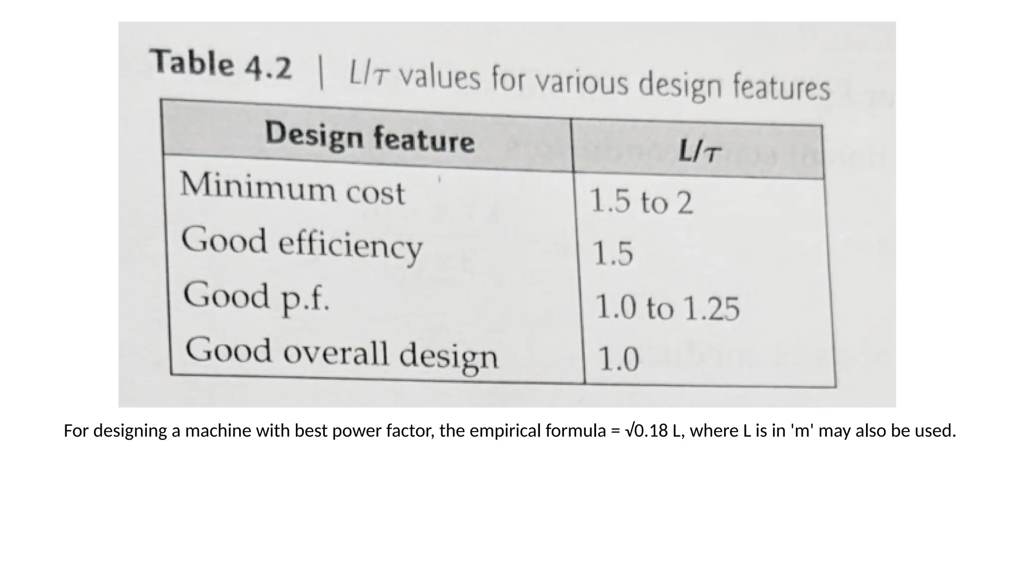
Table 4.2 gives the various values of L/τ usually used, based on the design feature of the machine.
11.
For designing amachine with best power factor, the empirical formula = √0.18 L, where L is in 'm' may also be used.
12.
4.7 Design ofStator of Three-phase Induction Motor :-
The following factors are to be considered in the design of stator of three-phase induction motor.
(a) Peripheral velocity
The calculated value of diameter 'D' has to result in peripheral velocity less than 30 m/s and is calculated as
Peripheral velocity, vs = πDns m/s
'D' has to be recalculated or special rotor construction is to be recommended if the peripheral velocity exceeds 30
m/s.
(b) Ventilating ducts
When the length of the core 'L' exceeds 16 to 18 cm, it is very difficult to cool the machine. Hence, radial ventilating
ducts of 8 to 10 mm are used. In this case, the gross core length is given as follows.
Gross core length, Lg=L-ndwd
where nd is the number of ducts, w, is the width of each duct.
13.
Net iron length,Li = ksLg
where ks - stacking factor
(c) Design of stator winding :-
The stator winding of a squirrel cage induction motor is designed for delta
connection, as this machine is generally started by a star-delta starter.
However, star connection can be adopted if other starting methods are
available.
For wound rotor motor, the stator winding would be either in
star or in delta.
14.
(i) Turns perphase of stator winding :-
The stator voltage per phase
Vph = 4.44 f Φm Tphkw
So, Stator turns per phase,
Tph = Vph/ 4.44 f
Φmkw
The winding factor Kw is 0.955 for full pitched
winding with 60" spread.
15.
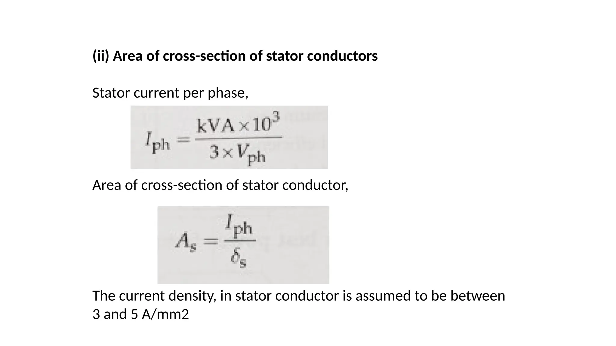
(ii) Area ofcross-section of stator conductors
Stator current per phase,
Area of cross-section of stator conductor,
The current density, in stator conductor is assumed to be between
3 and 5 A/mm2
16.
(ii) Design ofstator slots The performance of an
induction motor depends on the shape, size and
number of stator slots
(iii) (a) Shape of stator slots
Two types of stator slots are generally used in
induction motor stators, namely open slots and
semi-closed slots. Sometimes instead of semi-
closed slots, tapered slots are also used.
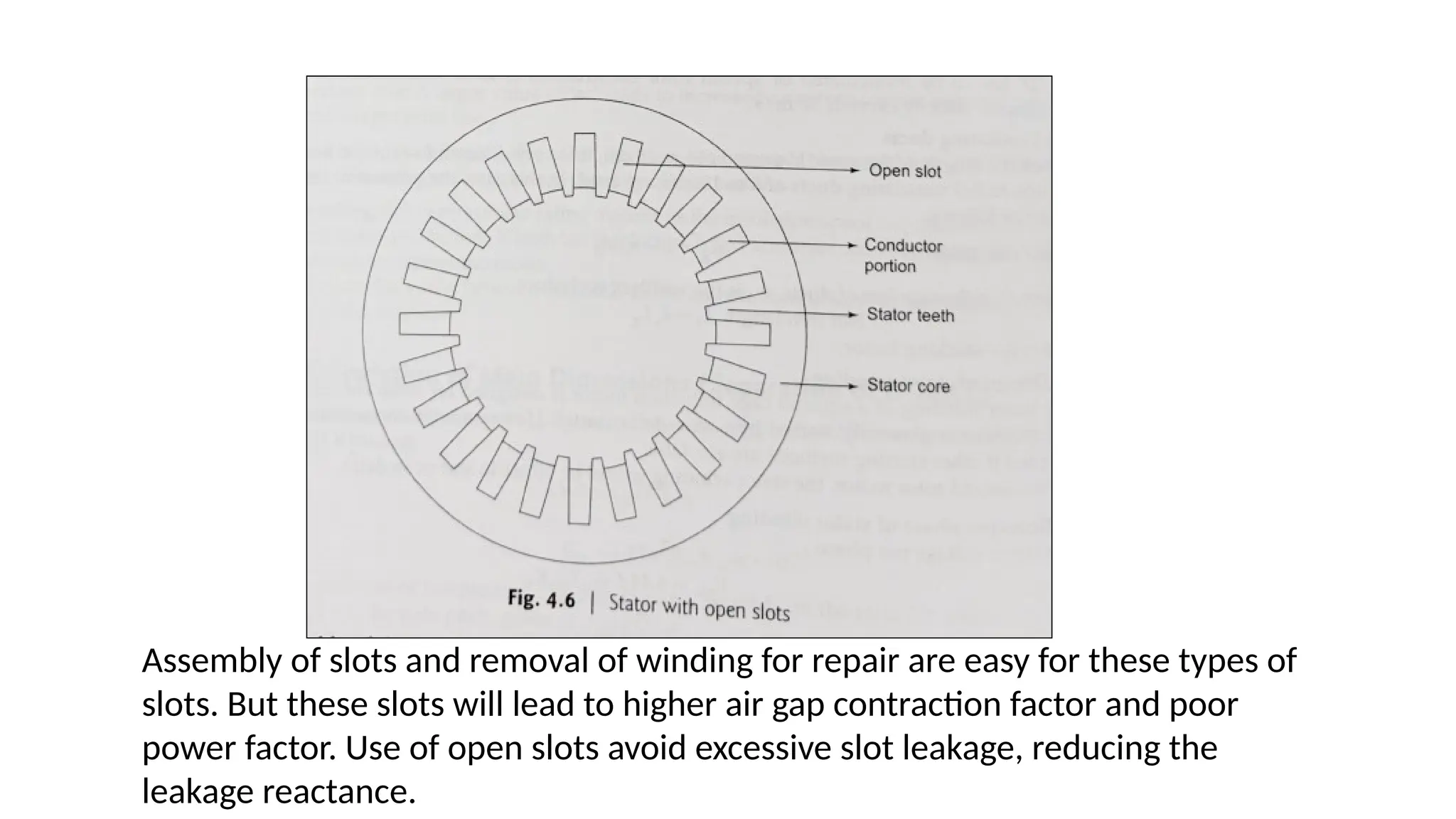
Open slots: In these types of slots, the slot
opening will be same as the width of the slot as
shown in Fig.
17.
Assembly of slotsand removal of winding for repair are easy for these types of
slots. But these slots will lead to higher air gap contraction factor and poor
power factor. Use of open slots avoid excessive slot leakage, reducing the
leakage reactance.
18.
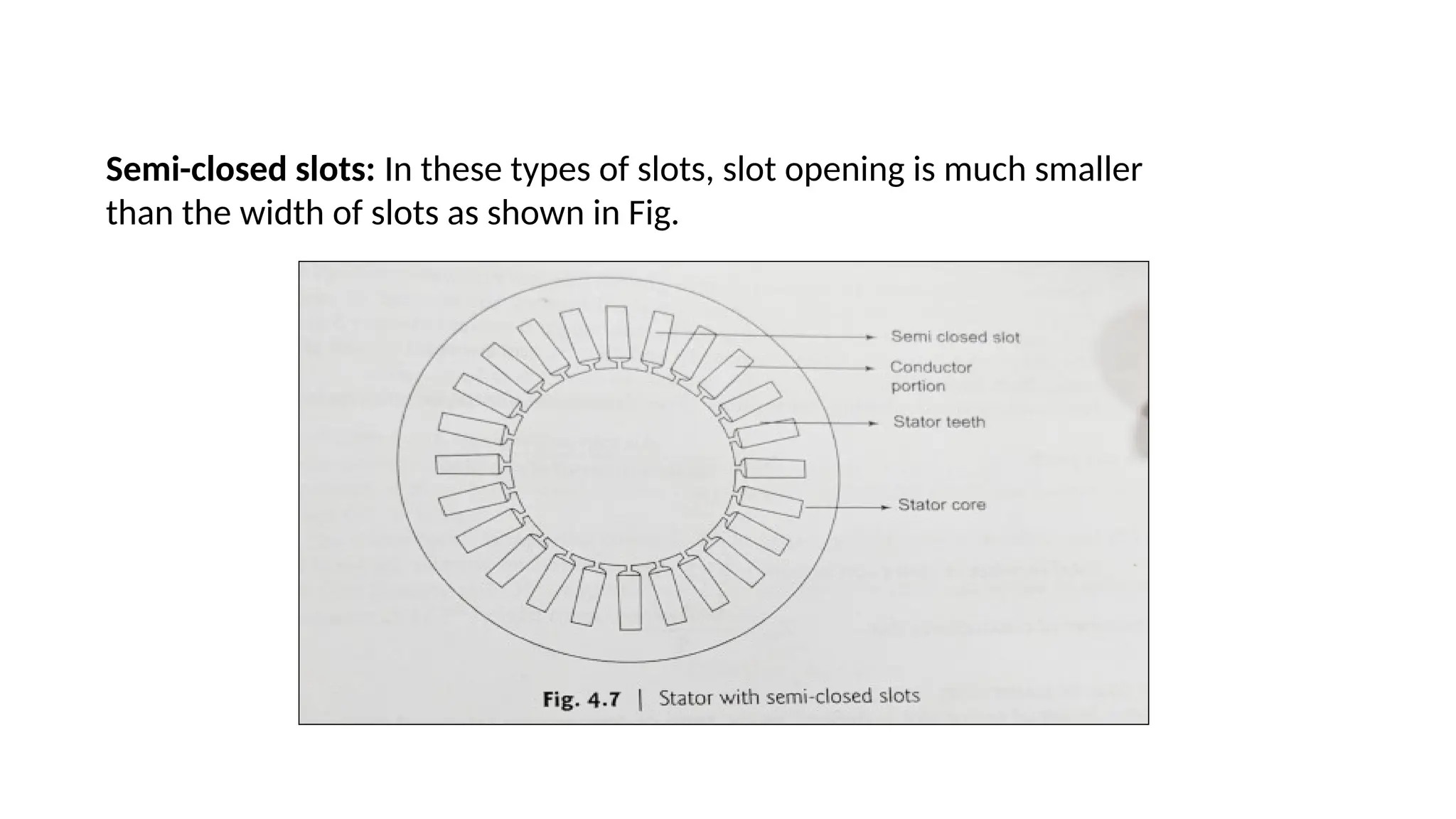
Semi-closed slots: Inthese types of slots, slot opening is much smaller
than the width of slots as shown in Fig.
19.
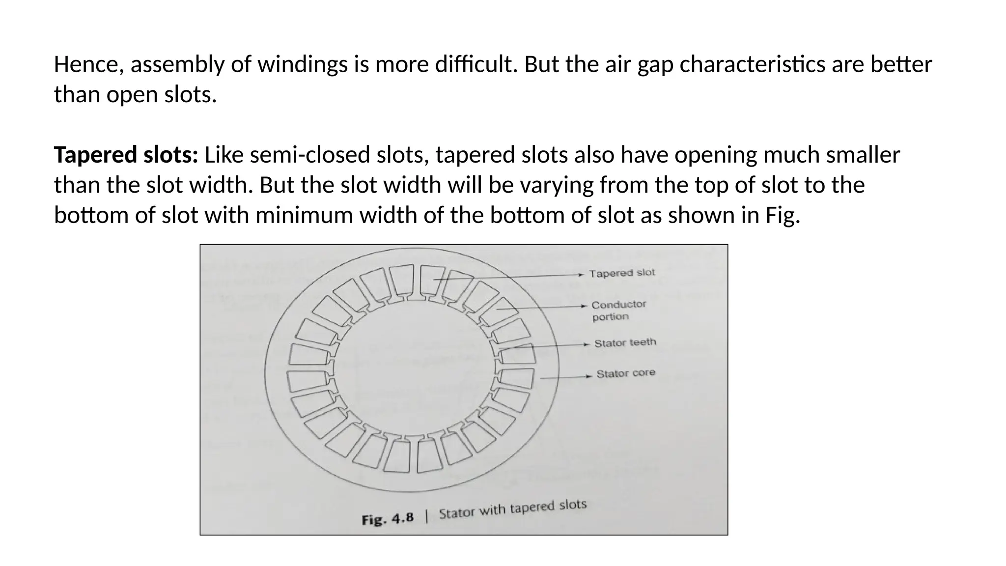
Hence, assembly ofwindings is more difficult. But the air gap characteristics are better
than open slots.
Tapered slots: Like semi-closed slots, tapered slots also have opening much smaller
than the slot width. But the slot width will be varying from the top of slot to the
bottom of slot with minimum width of the bottom of slot as shown in Fig.
20.
(iii) (b) Numberof stator slots
The following guidelines may be used to select suitable number of stator
slots.
(i) Number of slots should be selected so as to give an integral number of
slots per pole
per phase. Generally for small and medium sized motors, the number of
slots per pole phase varies between 3 and 5 and for narrow range it varies
between 3 and 4.
(ii) The slot pitch for open slot lies between 15 and 25 mm, and for semi-
closed slots, it varies from 20 to 25mm
(iii) For double-layered winding, the number of conductors/slot must be an
even integer.
22.
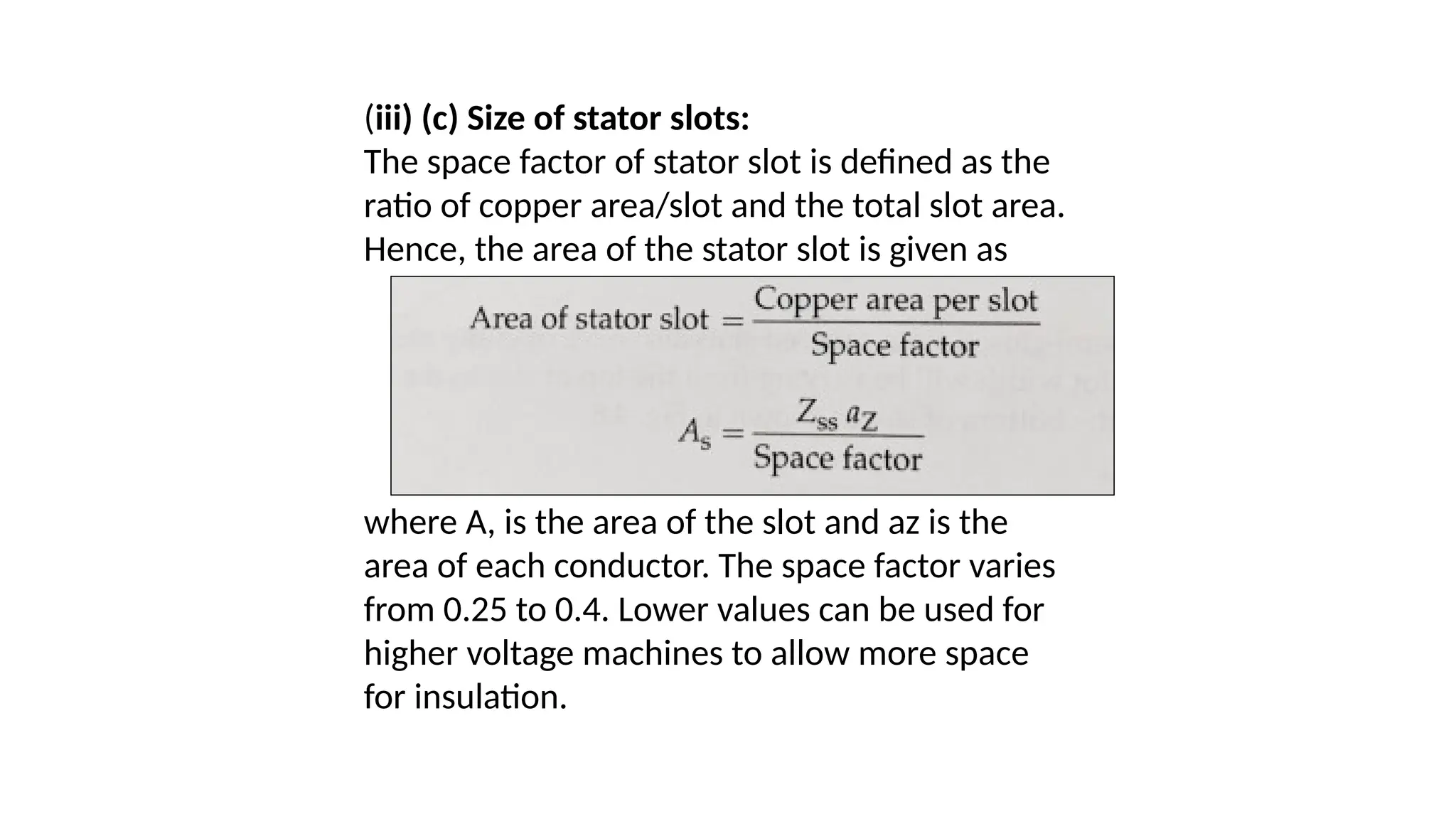
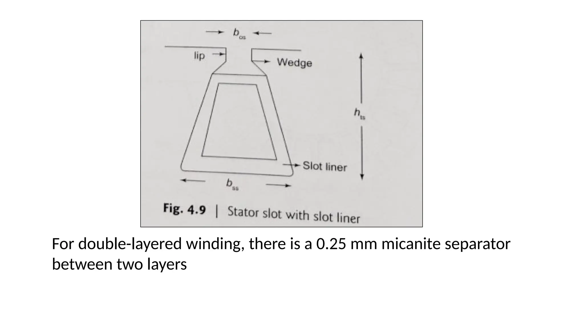
(iii) (c) Sizeof stator slots:
The space factor of stator slot is defined as the
ratio of copper area/slot and the total slot area.
Hence, the area of the stator slot is given as
where A, is the area of the slot and az is the
area of each conductor. The space factor varies
from 0.25 to 0.4. Lower values can be used for
higher voltage machines to allow more space
for insulation.
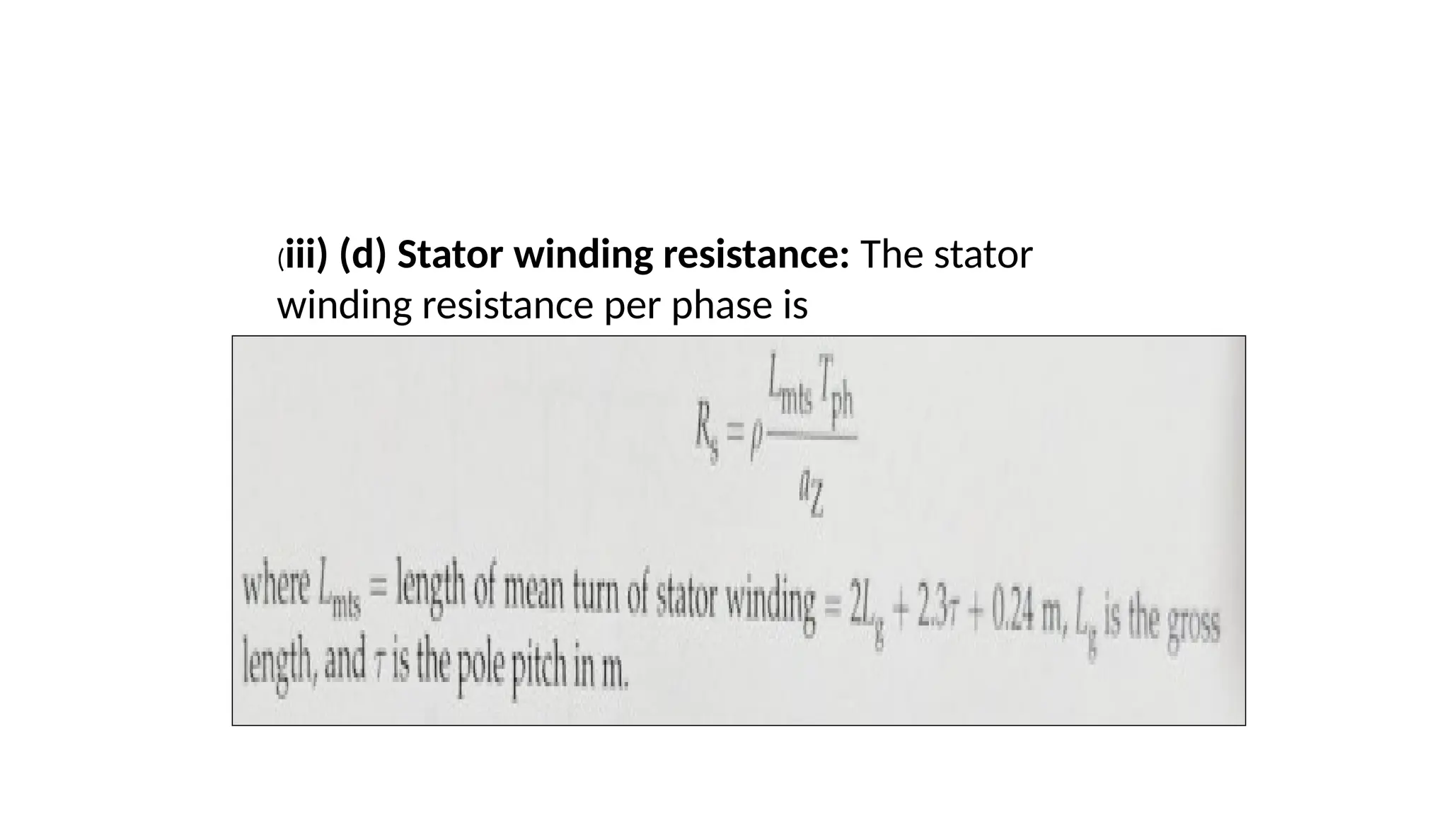
(iii) (d) Statorwinding resistance: The stator
winding resistance per phase is
25.
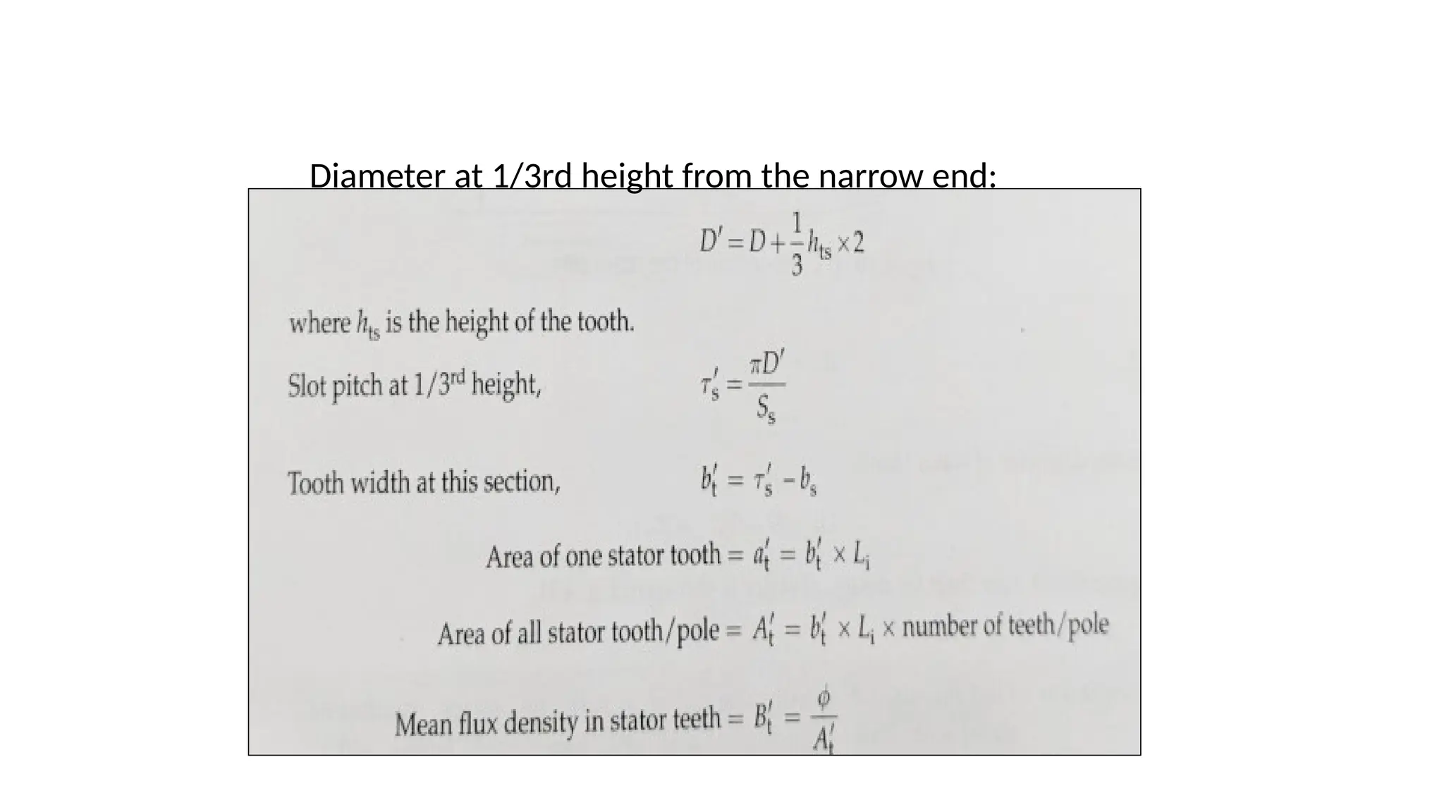
(iii) (e) Statorteeth design:
Once the slot dimension is fixed, the tooth
dimension is also fixed. However, it must be
checked to find out whether the flux density
in the tooth is within the range of 1.8 Tesla.
As the stator tooth is tapering towards the
bottom, the flux density is calculated at
1/3rd
height from the narrow end of the tooth.
The flux density at 1/3rd height from the
narrow end of tooth is calculated as follows.
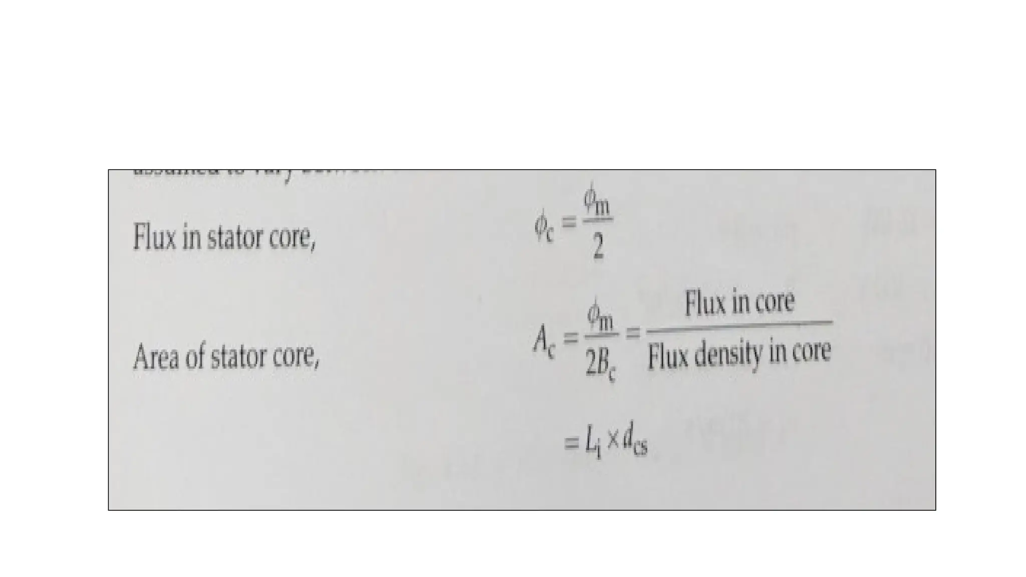
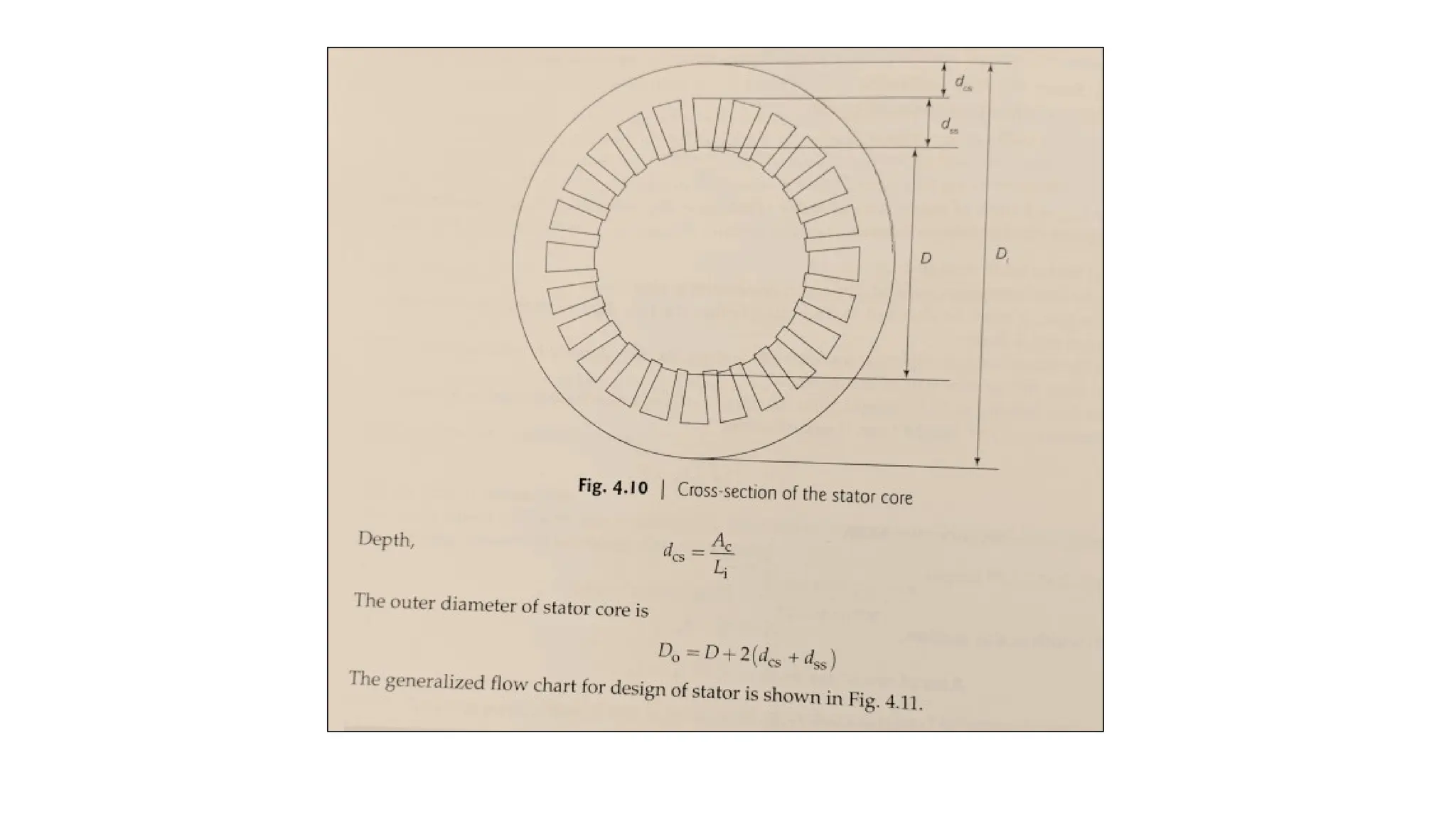
(iii) (f) Depthof stator core :
The cross-section of the stator core is
shown in Fig. 4.10.
There is some solid portion below the
slots in the stator. This depth is called
depth of stator core dcs.
This can be calculated by assuming
suitable value for flux density 'Bc' in
stator core. It is assumed to vary
between 1.2 and 1.4 Tesla.