THREE PHASE INDUCTIONMOTOR
• A 3-phase induction motor is an electromechanical energy
conversion device which converts 3-phase input electrical power into
output mechanical power.
• Three-phase induction motor is the most widely used motor in the
case of three-phase Alternating current operation, as this type of
motor does not require an additional starting device. This is why it is
also called a self-starting induction motor.
• A 3-phase induction motor has two main parts which are a stator and
a rotor.
• 3-phase stator winding is carried by the stator while the rotor carries
a short-circuited winding or rotor winding.
• A 3-phase supply is fed to stator winding. The rotor winding takes its
power and voltage from the stator winding through electromagnetic
induction.
3.
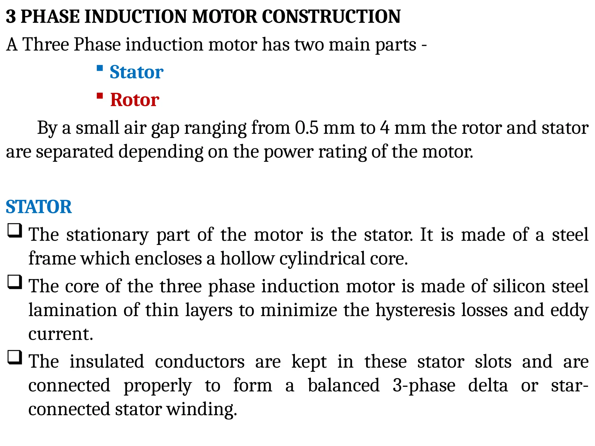
3 PHASE INDUCTIONMOTOR CONSTRUCTION
A Three Phase induction motor has two main parts -
Stator
Rotor
By a small air gap ranging from 0.5 mm to 4 mm the rotor and stator
are separated depending on the power rating of the motor.
STATOR
The stationary part of the motor is the stator. It is made of a steel
frame which encloses a hollow cylindrical core.
The core of the three phase induction motor is made of silicon steel
lamination of thin layers to minimize the hysteresis losses and eddy
current.
The insulated conductors are kept in these stator slots and are
connected properly to form a balanced 3-phase delta or star-
connected stator winding.
4.
• The 3-phasestator windings are configured with a specific number of
poles, depending on the requirement of speed, i.e., the greater the speed
of the motor, the lesser the number of poles and vice-versa.
• The connection between simultaneous speed and number poles is as
displayed in the below equation,
Ns = 120f / P
• When a balanced 3-phase supply is fed to the stator winding a rotating
magnetic flux (RMF) of constant magnitude is produced and this RMF
induces currents in the rotor circuit by electromagnetic induction.
ROTOR
• The rotor of an Induction motor is a laminated core hollow cylindrical,
slots are constructed on its outer periphery. On these rotor slots, the
rotor windings are placed.
• Depending upon the winding placement, the rotor of a 3-phase
induction motor is of two types −
– Squirrel Cage Type Rotor
– Wound Type or Slip-Ring Type Rotor
5.
• The rotoris separated from the stator by a small air-gap which
ranges from 0.4 mm to 4 mm, depending on the power and the size of
the motor
6.
SQUIRREL CAGE TYPEROTOR
• The squirrel cage rotor is made of a cylindrical laminated core,
Skewed slots are kept on its outer periphery which are nearly parallel
to the shaft axis. An insulated aluminum or copper bar (rotor
conductor) is placed in each slot.
• At both ends of the rotor, the rotor bar conductors are connected by
heavy end rings made from the same material creating a short-
circuit.
7.
This whole arrangementresembles a cage which was once normally
used for keeping squirrels hence the name
Currents are induced in the rotor by the electromagnetic induction from
the stator, and hence rotor is not connected electrically to the supply.
Those 3 phase induction motors which are known as squirrel cage
induction motors are those in which squirrel cage rotors are employed.
Squirrel cage rotor conductors are skewed because this offers the
following advantages
– The noise is reduced during operation.
– More uniform torque is produced.
– The magnetic locking tendency or cogging of the rotor is
reduced. Due to magnetic action cogging occurs, in which
the rotor and stator teeth lock with each other.
8.
ADVANTAGES OF SQUIRRELCAGE INDUCTION MOTOR
Simplicity: Squirrel cage motors have a basic and hearty turn of events, making
them smooth and solid.
Low Maintenance: There are fewer parts that are susceptible to wear and
maintenance issues because the rotor is a closed cage with no external connections.
High Starting Torque: In situations where high starting torque is required,
squirrel cage motors frequently exhibit excellent characteristics.
Wide Range Of Application: These motors are affordable for numerous modern
machines, such as pumps, fans, compressors, and others.
DISADVANTAGES OF SQUIRREL CAGE INDUCTION MOTOR
Limited Speed Control: Speed control options for squirrel cage motors are
limited, and their speed is largely determined by the voltage and frequency applied.
Limited Starting Control: While slip-ring motors have greater command over
starting force, squirrel cage motors typically have greater starting torque.
9.
WOUND ROTOR ORSLIP RING ROTOR
• The slip ring rotor is made of a laminated cylindrical armature core.
The slots are constructed on the outer periphery and insulated
conductors are placed in the slots.
• To form a 3-phase double layer distributed winding similar to the
stator winding the rotor conductors are connected. The rotor
windings are connected in star form.
10.
• The starconnection’s open ends are taken outside the rotor and
connected to three insulated slip rings.
• The slip rings are placed on the rotor shaft with brushes resting on
them.
• The brushes are linked to three variable resistors arranged in a star
configuration. Here, Brushes and slip rings are used to give a means
for connecting external resistors in the rotor circuit.
11.
ADVANTAGES OF SLIPRING INDUCTION MOTOR:
Starting current is low:
The rotor winding of a slip ring induction motor is connected to the outer
high variable resistor by slip rings, resulting in a lower beginning current.
Controlling the speed:
Because this motor contains an integrated variable resistor, it may be utilized
as a speed controller without the usage of an external speed controller. As a result, this
motor's speed can be adjusted more simply than other motors.
Acceleration is smooth:
The motor starting moment absorbs the least amount of electricity, resulting
in a low motor starting speed. When the rotor current is increased, the motor
accelerates smoothly under heavy load.
High torque during start-up:
Because the resistance of the rotor winding is raised by adding external
resistance, the slip ring induction motor has a high beginning torque. As the power
factor of the rotor circuit improves during startup, the beginning torque increases.
12.
DISADVANTAGES:
Regulation ofspeed:
This motor speed controller uses a variable resistor approach,
which isn't ideal for industrial use.
Price:
When compared to squirrel cage induction motors, this motor
has a higher startup and maintenance cost. Because a slip ring
induction motor requires more brushing and slip rings than
conventional motors, it is more expensive.
Heat:
In comparison to squirrel cage induction motors, slip ring
induction motors have poor heat regulation.
Large space:
Because the motor and the speed-controlling resistor are both in
the same unit, this motor requires a lot of room.
13.
APPLICATION OF 3PHASE INDUCTION MOTOR
In industrial applications mostly induction motor is used.
In residential as well as industrial applications the
squirrel cage induction motors are used especially when the speed
control of motors is not needed such as:
– Pumps and submersible
– Pressing machine
– Lathe machine
– Grinding machine
– Conveyor
– Flour mills
– Compressor
14.
• The slipring motors are used where heavy load applications
and high initial torque is required such as:
– Steel mills
– Lift
– Crane Machine
– Hoist
– Line shafts
15.
EQUIVALENT CIRCUIT OFINDUCTION MOTOR
With the help of an equivalent circuit, we can evaluate the steady-state
operation of the motor by simple network calculation and it enables us
to find the performance characteristics like rotor torque, losses, and
efficiency of the motor.
An induction motor works on the principle of electromagnetic
induction. The working of an induction motor is similar to the
transformer. Also, an equivalent circuit of an induction motor is similar
to the equivalent circuit of a transformer.
The energy transfers in an induction motor from stator to rotor is a
quite similar operation as energy transfers in the transformer from
primary to secondary.
16.
SLIP:
• The inductionmotor always run below synchronous speed.
The relative speed between the synchronous speed and actual rotor
speed is known as slip. The equation of slip and synchronous speed is
shown in the below equation.
Where,
Ns = Synchronous speed =
N = Speed of rotor (actual speed)
STATOR CIRCUIT MODEL:
17.
• The statorconsists of the stator winding and stator core.
• The loss produced in the stator winding is represented by the stator
resistance R1 and the loss produced in the stator core is represented
by the stator reactance X1. Therefore, the stator circuit model consists
of a stator resistance(R1) and stator reactance(X1) connected in series.
• he no-load current I0 is divided into two parts; magnetizing current
Iμ and core-loss current Iω.
I0 = Iμ + Iω
• A pure inductive reactance X0 carries magnetizing current Iμ and
non-inductive resistance carries core-loss current Iω.
• Due to the higher reluctance caused by the air gap in the case of the
induction motor, the total magnetizing current is larger compared to
the transformer.
18.
• In aninduction motor, the no-load current is 25 to 40% of the rated
current and in a transformer, the no-load current is 2 to 5% of the
rated current..
ROTOR CIRCUIT MODEL
• When a three-phase supply is given to the stator winding, the EMF is
induced in the rotor winding.
• The rotor voltage depends on the relative motion of the rotor and
stator magnetic field. The largest relative motion is achieved at
standstill condition.
• The rotor voltage induced at any slip is given by;
E2s = SE20
• If we ignore the skin effect, the rotor resistance is constant and it is
independent of the slip.
• The rotor reactance depends on the rotor frequency and inductance.
The rotor reactance is given by;
X2 = 2πf2 L2
19.
Where f2 =rotor frequency
L2 = rotor inductance
• The relation between supply frequency f1 and rotor frequency f2 is
given by;
f2 = sf1
X2 = 2 sf
π 1 L2
X2 = sX20
Where; X20 = standstill reactance of rotor
• The circuit diagram of the rotor circuit model is shown in the figure
below.
20.
• From theabove figure, the rotor impedance is given by;
Z2s = R2 + jX2s
Z2s = R2 + jsX20
The rotor current is given by;
• From this equation, it is noted that I2s is a slip-frequency current
produced by slip-frequency voltage sE20 and rotor circuit having an
impedance of R2 + jX2s.
• If we divide the above equation by slip s, we get;
21.
• The representationof this equation is shown in the figure below.
• This equation describes similarity with the secondary winding of
transformer having a constant voltage ratio and same frequency of
both sides. Here, we assume a stationary rotor that carries the same
current as the actual rotating rotor and produces the same MMF.
This imaginary stationary rotor makes it possible to transfer
secondary (rotor) impedance to the primary (stator) side.
• In the case of induction motor, when the rotor current and voltages
are referred to stator side, their frequency is also changed to stator
frequency.
22.
Exact Equivalent Circuitof Induction Motor
• To derive the exact per-phase equivalent circuit of an induction
motor, we need to calculate the rotor part of a model over to the
stator circuit’s frequency and voltage level.
• In the transformer equivalent circuit, the voltage, current, and
impedance on the secondary side are transferred to the primary side
with the help of the turns ratio (a).
• A similar transformation can be done in the case of the induction
motor.
E2‘ = a E2 = E1
R2‘ = a2
R2
X20‘ = a2
X20
23.
• The approximateequivalent circuit of the induction motor is shown
in the figure below.
• As shown in the above figure, one resistance depends on the slip s.
This resister represents the developed mechanical power by the rotor.
• All other components are constant. Reactance shown in the figure
correspond to the fixed stator frequency f1.
24.
SPEED CONTROL OFTHREE PHASE INDUCTION MOTOR
• A three phase induction motor typically operates at a constant speed,
making its speed control challenging. Controlling the induction motor
speed can lead to reduced efficiency and a lower electrical power factor.
• It’s essential to understand the basic formulas for speed and torque of a
three-phase induction motor, as these underpin various speed control
methods.
SYNCHRONOUS SPEED
Ns = 120f / P
Where,
f = frequency and P is the number of poles
• The speed of induction motor is given by,
N=Ns(1-S)
Where,
N is the speed of the rotor of an induction motor,
Ns is the synchronous speed,
S is the slip.
25.
• The torqueproduced by three phase induction motor is given by,
• When the rotor is at standstill slip, s is one.
So the equation of torque is,
• Where,
E2is the rotor emf
Ns is the synchronous speed
R2 is the rotor resistance
X2 is the rotor inductive reactance
26.
• The Speedof Induction Motor is changed from Both Stator and Rotor
Side. The speed control of three phase induction motor from stator
side are further classified as :
V / f control or frequency control.
Changing the number of stator poles.
Controlling supply voltage.
Adding rheostat in the stator circuit.
• The speed controls of three phase induction motor from rotor side
are further classified as:
Adding external resistance on rotor side.
Cascade control method.
Injecting slip frequency emf into rotor side.