This document presents a MATLAB/Simulink modeling technique for analyzing a star-connected 3-phase induction motor (IM) under open-phase fault conditions, utilizing a d-q model for performance assessment. It details the equations governing the faulty IM and illustrates the step-by-step simulation process that demonstrates the motor's dynamic behavior in both no-load and load conditions. The results indicate that the motor exhibits increased oscillations in speed and torque during faults compared to normal operation, confirming the viability of using MATLAB/Simulink for such analyses.
![International Journal of Power Electronics and Drive System (IJPEDS)
Vol. 7, No. 4, December 2016, pp. 1146~1152
ISSN: 2088-8694, DOI: 10.11591/ijpeds.v7i4.pp1146-1152 1146
Journal homepage: http://iaesjournal.com/online/index.php/IJPEDS
Modelling of a 3-Phase Induction Motor under Open-Phase
Fault Using Matlab/Simulink
Mohammad Jannati1
, Tole Sutikno2
1
UTM-PROTON Future Drive Laboratory, Faculty of Electrical Engineering, Universiti Teknologi Malaysia,
Johor Bahru, Malaysia
2
Department of Electrical Engineering, Universitas Ahmad Dahlan, Yogyakarta, Indonesia
Article Info ABSTRACT
Article history:
Received May 28, 2016
Revised Nov 2, 2016
Accepted Nov 14, 2016
The d-q model of Induction Motors (IMs) has been effectively used as an
efficient method to analyze the performance of the induction machines. This
study presents a step by step Matlab/Simulink implementation
of a star-connected 3-phase IM under open-phase fault (faulty 3-phase IM)
using d-q model. The presented technique in this paper can be simply
implemented in one block and can be made available for control purposes.
The simulated results provide to show the behavior of the star-connected
3-phase IM under open-phase fault condition.Keyword:
Control purposes
D-q model
Matlab/Simulink
Open-phase fault
Star-connected 3-phase IM Copyright © 2016 Institute of Advanced Engineering and Science.
All rights reserved.
Corresponding Author:
Mohammad Jannati,
Faculty of Electrical Engineering,
Universiti Teknologi Malaysia,
UTM Skudai, 81310 Johor, Malaysia.
Email: jannatim94@yahoo.com
1. INTRODUCTION
Induction Motors (IMs) are the most robust and the most broadly used machines in industrial
sectors. To show the behavior of IMs, the modeling of these motors is very important. The modeling of these
motors is needed in calculations of fault, voltage drop, control applications, transient analysis and etc [1]-[7].
Due to the complexity of the solving differential equations of a 3-phase IM, a change of variables
can be applied to decrease the complexity of these equations. In this method, 3-phase windings can be
reduced to a set of 2-phase windings (q-d model). In other words, the 3-phase IM stator and rotor variables
are transferred to a reference frame, which can rotate at any angular velocity. This method is a powerful
technique in implementing the IM equations [8].
Due to the asymmetrical structure of a 3-phase IM under open-phase fault (faulty 3-phase IM), the
d-q model of a healthy 3-phase IM is different from a faulty 3-phase IM [9]. In this paper, we present a
contribution to the issue of d-q model of a star-connected 3-phase IM with one phases cut-off based on [9].
The published paper in [9] investigates the d-q model of a star-connected 3-phase IM with one phase cut-off.
The performance of presented model in [9] is simulated using Matlab/M-File. However, it was found that
Matlab/Simulink is more convenient in terms of simplicity in structure and control algorithms.
Matlab/Simulink has benefit over other electric machine simulators in modeling the IM using d-q
axis transformation. In this research, Matlab/Simulink is applied to simulate and analyze the dynamic
performance of a star-connected 3-phase IM under stator winding open-phase fault condition. The provided
faulty 3-phase IM model is simulated in a way that makes it understandable for the reader to follow and
realize the simulation process since it gives full details about Simulink of the model equations. This paper is](https://image.slidesharecdn.com/1228aug1612283-25710-1-rvedita-171220071122/75/Modelling-of-a-3-Phase-Induction-Motor-under-Open-Phase-Fault-Using-Matlab-Simulink-1-2048.jpg)
![ ISSN: 2088-8694
IJPEDS Vol. 7, No. 4, December 2016 : 1146 – 1152
1147
organized as follows: after introduction in section 1, in section 2, the mathematical model of a star-connected
3-phase IM under open-phase fault is presented. In section 3, simulation of a faulty 3-phase IM using
Matlab/Simulink is presented. To check the performance of the presented method, Matlab/Simulink results
are presented in section 4. Conclusions are listed in section 5.
2. FAULTY 3-PHASE IM EQUATIOS
For the purposes of the current research, the faulty 3-phase IM equations are shown by the following
equations (in these equations superscript “s” shows the use of a stationary reference frame) [9]:
Stator voltage equations
s
qr
s
dr
q
d
s
qs
s
ds
qss
dss
s
qs
s
ds
i
i
pM
pM
i
i
pLr
pLr
v
v
0
0
0
0
(1)
Stator flux equations
s
qr
s
dr
q
d
s
qs
s
ds
qs
ds
s
qs
s
ds
i
i
M
M
i
i
L
L
0
0
0
0
(2)
Rotor voltage equations
s
qr
s
dr
rrrr
rrrr
s
qs
s
ds
qdr
qrd
s
qr
s
dr
i
i
pLrL
LpLr
i
i
pMM
MpM
v
v
0
0
(3)
Rotor flux equations
s
qr
s
dr
r
r
s
qs
s
ds
q
d
s
qr
s
dr
i
i
L
L
i
i
M
M
0
0
0
0
(4)
Torque equations
s
qr
s
dsd
s
dr
s
qsqe iiMiiM
pole
T
2
(5)
rrle FJp
pole
TT
2
(6)
In (1)-(6), vs
ds, vs
qs, vs
dr, vs
qr, φs
ds, φs
qs, φs
dr, φs
qr, is
ds, is
qs, is
dr, is
qr are the stator voltages, the rotor
voltages, the stator fluxes, the rotor fluxes, the stator currents and the rotor currents. rs, rr, Lds, Lqs, Lr, Md, Mq
are the stator and rotor resistances, the stator and rotor self and mutual inductances. r is the motor electrical
speed. p=d/dt. Te, Tl, J and F are the electromagnetic torque, the load torque, the moment of inertia and the
viscous friction coefficient respectively. Moreover [9],
mslsqsmslsdsmsqmsd LLLLLLLMLM
2
1
,
2
3
,
2
3
,
2
3
(7)
In other words, based on equation (7), during open-phase fault condition, only the stator q-axis self
and mutual inductances (Lqs and Mq) are changed and the stator d-axis self and mutual inductances
(Lds and Md) remained unchanged.
The stator and rotor voltages, fluxes and currents during open-phase fault condition are transferred
to d-q axis transformation. This can be performed using the following equations [9].](https://image.slidesharecdn.com/1228aug1612283-25710-1-rvedita-171220071122/75/Modelling-of-a-3-Phase-Induction-Motor-under-Open-Phase-Fault-Using-Matlab-Simulink-2-2048.jpg)
![IJPEDS ISSN: 2088-8694
Modelling of a 3-Phase Induction Motor under Open-Phase Fault Using Matlab/Simulink (M. Jannati)
1148
11
11
2
2
sT (8)
2
3
2
3
0
2
1
2
1
1
3
2
rT (9)
In (8) and (9), [Ts] and [Tr] are transformation matrices for the stator and rotor variables
respectively. As can be seen, during open-phase fault condition, the rotor transformation matrix is the same
as conventional one. However, the stator transformation matrix is different. The configuration of the 3-phase
power supply fed 3-phase IM during open-phase fault condition used in this paper is shown in Figure 1.
Figure 1. 3-Phase IM during Open-Phase Fault Condition
In Figure 1, the 3-phase stator voltages of an IM can be expressed as:
tvv ma sin (10)
3
2
sin
tvv mb (11)
3
2
sin
tvv mc (12)
3. SIMULATION OF A FAULTY 3-PHASE IM USING MATLAB/SIMULINK
In this section, a faulty 3-phase IM model is simulated using the Matlab/Simulink. The Model is
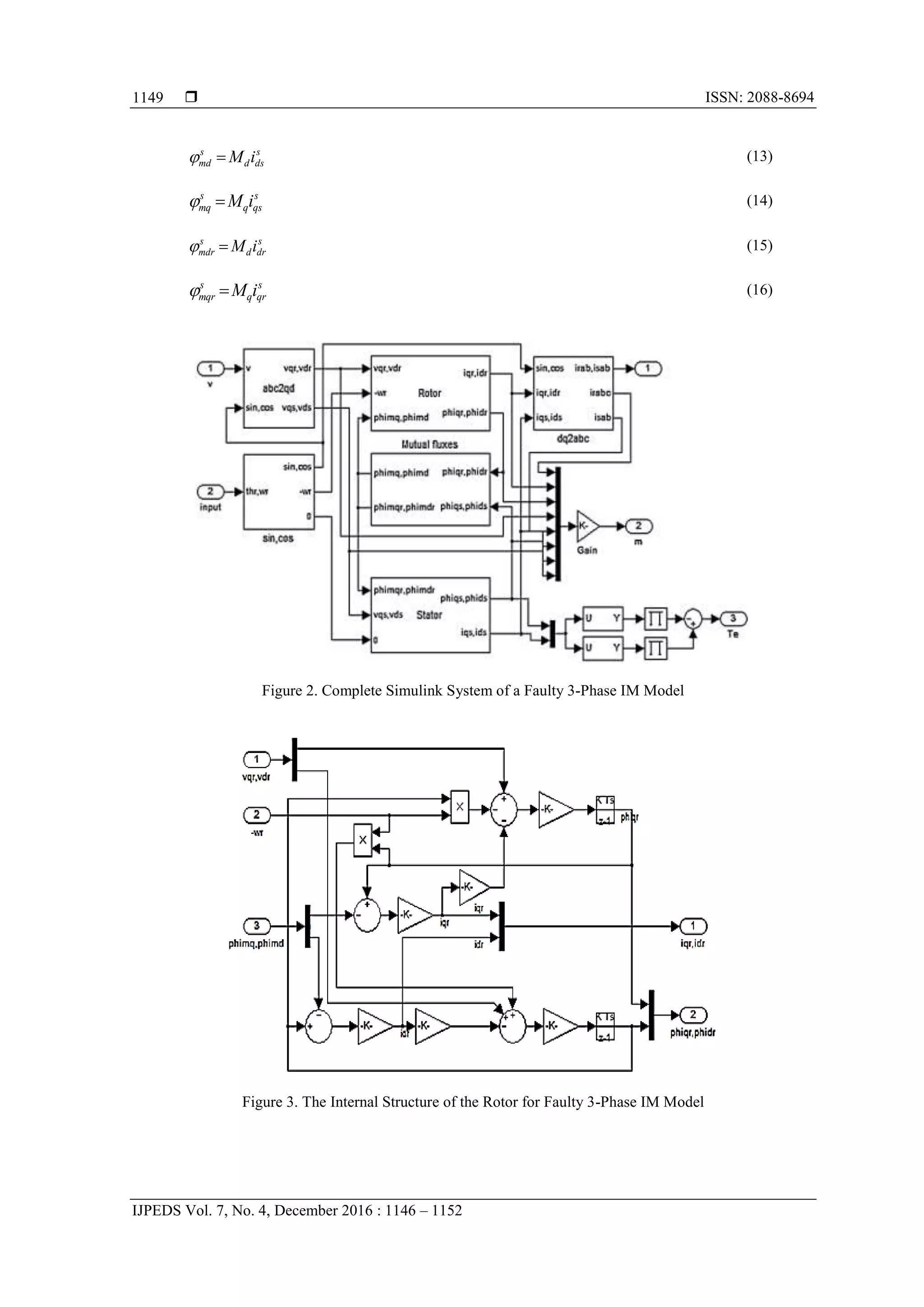
implemented using the equations provided in sections 2 (equations (1)-(7)). Figure 2 shows the complete
Simulink system of the described faulty 3-phase IM model. Generally, this block diagram includes five
sections: rotor, stator, fluxes, transformations and torque blocks.
In this model, the simulation starts with producing stator and rotor voltages giving in equations
(10)-(12), and then transforming these voltages to 2-phase voltages using transformation matrices according
to the equations (8) and (9). After that, the stator, rotor, torque and flux equations in the d-q frame were
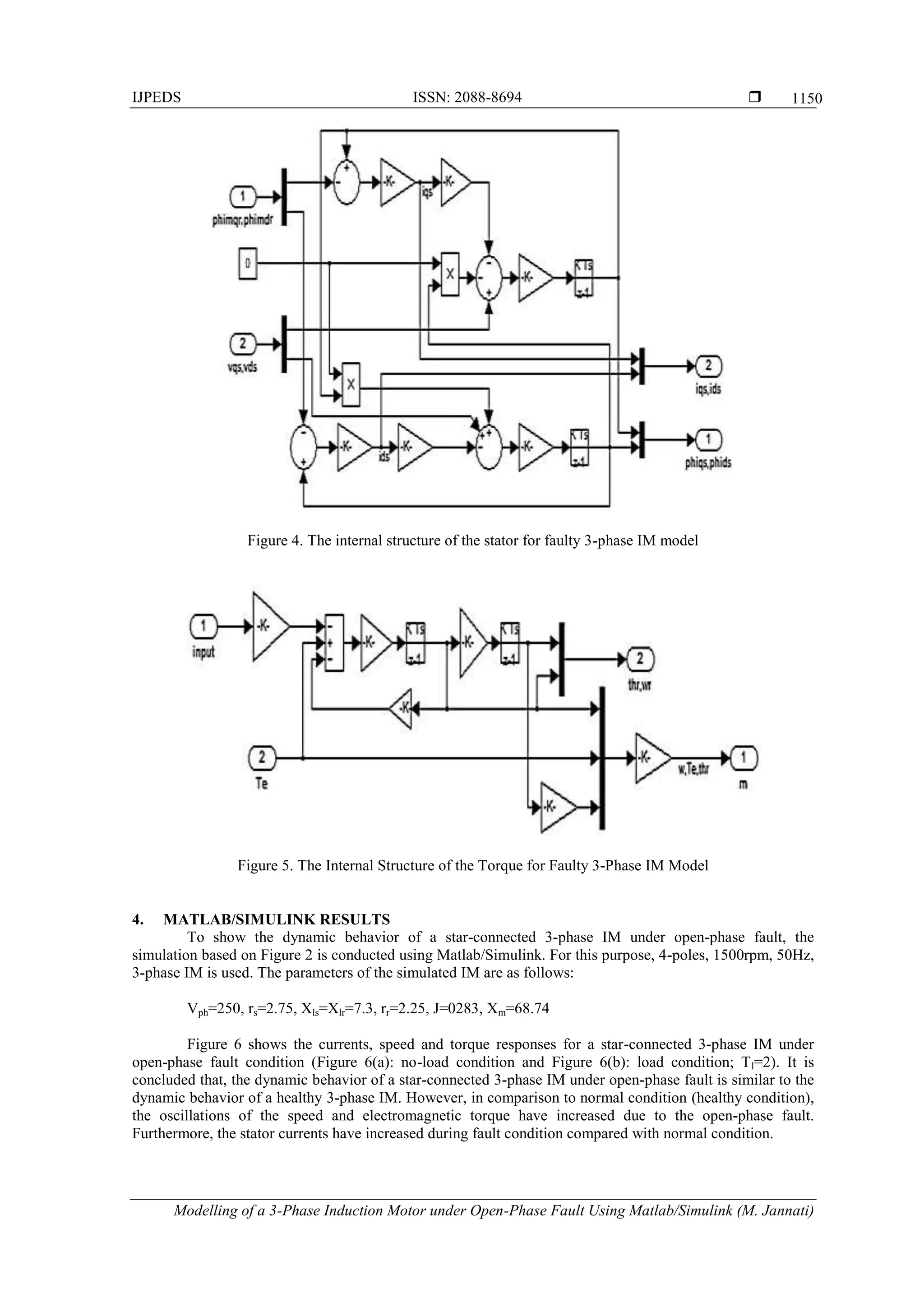
implemented as below. Figure 3 shows the internal structure of the rotor for faulty 3-phase IM model.
Figure 3 shows the Simulink blocks used to calculate the d-q rotor currents and d-q rotor fluxes according to
the equations (3) and (4). Figure 4 shows the internal structure of the stator for faulty 3-phase IM model.
Figure 4 indicates the Simulink blocks used to calculate the d-q stator currents and d-q stator fluxes
according to the equations (1) and (2). Figure 5 displays the internal structure of the torque and motor speed
for faulty 3-phase IM model. Figure 5 shows the Simulink blocks used to calculate the electromagnetic
torque and motor speed according to the equations (5) and (6).
Finally, equations (13)-(16) indicate the internal structure of the fluxes for faulty 3-phase IM model.](https://image.slidesharecdn.com/1228aug1612283-25710-1-rvedita-171220071122/75/Modelling-of-a-3-Phase-Induction-Motor-under-Open-Phase-Fault-Using-Matlab-Simulink-3-2048.jpg)
![IJPEDS ISSN: 2088-8694
Modelling of a 3-Phase Induction Motor under Open-Phase Fault Using Matlab/Simulink (M. Jannati)
1152
The presented model was verified under no-load and load conditions. It is concluded that it is possible to
analyze the behavior of a faulty 3-phase IM using Matlab/Simulink with some changes in the Simulink block
diagram of a healthy 3-phase IM. In the future, a study is to be conducted applying a step by step
Matlab/Simulink implementation of a delta-connected 3-phase IM under open-phase fault condition.
REFERENCES
[1] S. Li, Y. Fan, J. Fang, W. Qin, G. Lv, and J.H. Li, "HTS axial flux induction motor with analytic and FEA
modeling", Physica C: Superconductivity, vol. 494, pp. 230–234, 2013.
[2] S.D. Sudhoff, B.T. Kuhn, K.A. Corzine, and B.T. Branecky, "Magnetic equivalent circuit modeling of induction
motors", IEEE Transactions on Energy Conversion, vol. 22, no. 2, pp. 259–270, 2007.
[3] D.G. Dorrell and F. Jensen, "Modeling split-phase induction motors with center-tapped windings and asynchronous
torque dips", IEEE Transactions on Industry Applications, vol. 45, no. 1, pp. 168–177, 2009.
[4] E. Ramprasath and P. Manojkumar, "Modelling and Analysis of Induction Motor using LabVIEW", International
Journal of Power Electronics and Drive Systems, vol. 5, no. 3, pp. 344–354, 2015.
[5] J. Pedra, I. Candela, and L. Sainz, "Modelling of squirrel-cage induction motors for electromagnetic transient
programs", IET Electric Power Applications, vol. 3, no. 2, pp. 111–122, 2009.
[6] M. Jannati, T. Sutikno, N.R.N. Idris, and M.J.A. Aziz, "Modeling of Balanced and Unbalanced Three-Phase
Induction Motor under Balanced and Unbalanced Supply Based on Winding Function Method", International
Journal of Electrical and Computer Engineering, vol. 5, no. 4, pp. 644–655, 2015.
[7] S.H. Asgari, M. Jannati, and N.R.N. Idris, "Modeling of three-phase induction motor with two stator phases open-
circuit", In 2014 IEEE Conference on Energy Conversion (CENCON), 2014, pp. 231–236.
[8] P.C. Krause, "Analysis of Electric Machinery", McGraw-Hill, 1986.
[9] M. Jannati, N.R.N. Idris, and Z. Salam, "A new method for modeling and vector control of unbalanced induction
motors", In Energy Conversion Congress and Exposition (ECCE), 2012, pp. 3625–3632.](https://image.slidesharecdn.com/1228aug1612283-25710-1-rvedita-171220071122/75/Modelling-of-a-3-Phase-Induction-Motor-under-Open-Phase-Fault-Using-Matlab-Simulink-7-2048.jpg)