Downloaded 55 times
![INTERNATIONAL JOURNAL OF MECHANICAL ENGINEERING
International Journal of Mechanical Engineering and Technology (IJMET), ISSN 0976 – 6340(Print),
ISSN 0976 – 6359(Online), Volume 5, Issue 8, August (2014), pp. 60-72 © IAEME
AND TECHNOLOGY (IJMET)
ISSN 0976 – 6340 (Print)
ISSN 0976 – 6359 (Online)
Volume 5, Issue 8, August (2014), pp. 60-72
© IAEME: www.iaeme.com/IJMET.asp
Journal Impact Factor (2014): 7.5377 (Calculated by GISI)
www.jifactor.com
60
IJMET
© I A E M E
MODELLING AND OPTIMIZATION OF ELECTROMAGNETIC TYPE
ACTIVE CONTROL ENGINE-MOUNT SYSTEM
Prabhat Kumar Sinha, Dan Bahadur Patel*, Mohd Tariq, SaurabhaKumar
Mechanical Engineering Department, Shepherd School of Engineering and Technology,
Sam Higginbottom Institute of Agriculture, Technology and Sciences Allahabad U.P. 211007 India
ABSTRACT
This paper presents a low-cost prototype active control engine mount (ACM) designed for
commercial passenger vehicles, requiring a good engine vibration isolation performance. To
construct such an ACM system, all feedback sensors normally required for full ACM systems are
replaced by the model based feed forward algorithm, consisting of a vibration estimation algorithm, a
current shaping controller and an enhanced ACM model. The current shaping control compensates
for degradation of control performance due to elimination of feedback control sensors. The proposed
current shaping control improves the actuator control performance, and the vibration estimation
algorithm provides the anti-vibration signals for vibration isolation
The dynamic loads that are generated due to the shaking forces within the engine and the road
loads that are transmitted to the engine through the tire patch are discussed. The geometrical shape of
the engine mount is also considered in this work. All models discussed herein deal with solving the
optimization problem for the engine mount system such that the transmitted forces to and from the
engine are minimized in which the mount parameters are used as design variables. While work has
been done in the past in the area of engine mount design, this dissertation tries to fill in the gap when
it comes to designing a comprehensive mounting system that takes into account modeling of the
mount characteristics, the excitation load present in the system, and a determination of the final
geometrical shape of the engine mount.
Keyword: Vibrations, Sensor, Actuator.
INTRODUCTION
In recent years, various types of ACMs have been developed by many researchers. Y.W. Lee
[2] proposed an ACM that used a pneumatic actuator as an active system. The ACMs activated by
piezo-electric actuators were developed by M. Hideki and T. Mikasa [3]. The electromagnetic type](https://image.slidesharecdn.com/modellingandoptimizationofelectromagnetictypeactivecontrolenginemountsystem-141023073914-conversion-gate01/85/Modelling-and-optimization-of-electromagnetic-type-active-control-engine-mount-system-1-320.jpg)
![International Journal of Mechanical Engineering and Technology (IJMET), ISSN 0976 – 6340(Print),
ISSN 0976 – 6359(Online), Volume 5, Issue 8, August (2014), pp. 60-72 © IAEME
ACMs were evolved to utilize their high specific force per unit volume. Recently, Japanese
automotive companies such as Toyota, Nissan, and Honda introduced ACMs to the automotive
market. They provided the good vehicle tested mount results and highlighted improvements in
isolation of force induced by engine roll motion over the low frequency region of interest.
61
This research mainly focuses on development of an ACM designed for low-cost and, yet
satisfactory vibration isolation performance. A full loaded ACM system normally requires two
sensors: one for measurement of engine vibration or transmitted force through ACM, and the other
for position feedback of actuator itself. Without such sensors, the performance of ACM will degrade,
compared with the full loaded ACM. In this paper, a model based feed forward algorithm, which
consists of a vibration estimation algorithm, a current shaping controller and an improved ACM
model, is adopted, in order to compensate for the performance degradation due to absence of the
feedback sensors. The engine vibration estimator indirectly monitors the engine vibrations using the
signals taken from the existing sensors such as CAM and CAS [12–14]. The current shaping
controller compensates for the undesired harmonic distortion in the actuator output due to lack of its
position feedback. The improved ACM model is developed to accurately describe the active as well
as passive characteristics of ACM.
2. STRUCTURE OF ACM
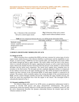
To isolate the engine-induced vibration, many researchers have developed various kinds of
ACMs [6–11], but their basic structures are similar to each other, as illustrated in Fig. 1. These were
achieved by different methods from the full loaded ACM system. Undesired harmonics due to the
free vibration of actuating system was reduced to some extent by the filter orifice, but it increased the
dynamic stiffness of the ACM system in the high frequency region, and then amplified the vibration
transfer via the ACM. The low-cost ACMs provided good vibration isolation performance in vehicle
tests, but there still remain problems in engine vibration estimation technique, controller of the ACM
system and proper mathematical model for design and control.
In this paper, three major contributions are made. First, a refined ACM model, which
accounts for the actuator model and base motion, is proposed to get the required force information
for control and design of ACM actuator. Second, a current shaping algorithm based on the ACM
model is suggested in order to compensate for the performance degradation due to absence of
feedback sensors without any side effects. Third, an engine vibration estimation algorithm, which
uses such existing sensors as CAM and CAS, is extended to construct the gain map easily by
applying an in-situ engine vibration estimation method using back EMF (electromotive force) of the
actuator coil and engine-mounting system model. The prototype low- cost ACM construction is
depicted in Fig. 2, which consists of three components: an ACM device, a current shaping controller
and an engine vibration estimator. As a result, main difference between the low-cost ACM and full
loaded ACM is absence of two feedback sensors, a displacement sensor for actuator control and a
load cell for reference signal. To help understanding, cost comparison between the two is described
in Table 1.](https://image.slidesharecdn.com/modellingandoptimizationofelectromagnetictypeactivecontrolenginemountsystem-141023073914-conversion-gate01/85/Modelling-and-optimization-of-electromagnetic-type-active-control-engine-mount-system-2-320.jpg)
![International Journal of Mechanical Engineering and Technology (IJMET), ISSN 0976 – 6340(Print),
ISSN 0976 – 6359(Online), Volume 5, Issue 8, August (2014), pp. 60-72 © IAEME
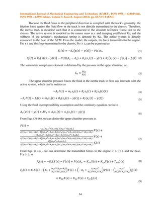
Fig. 3: Conventional hydraulic engine mount Fig. 4: The developed active control engine mount
The conventional HEM model, which has been proposed and optimized in the past by many
researchers [26–33], was incorporated into the ACM model to describe the active as well as passive
characteristics, accounting for dynamics of the active actuator. Lee and Lee [10] suggested a two-input
single-output system as an ACM model, treating the engine vibration and the actuator runner
displacement as the two independent inputs and the resulting transmitted force to the chassis as the
output. The passive and active transfer functions, defined from the two-input single-output
relationship, were extensively used for design and control of the ACM [10]. Sakamoto and Sakai
[15] proposed a modified ACM model that reflects the actuator dynamics to explain the passive
characteristics more precisely
In Fig. 5, Kr and Cb represent the stiffness and volumetric compliance of rubber,
respectively; Ac and At denote the cross-sectional areas of the actuator runner and the inertia track,
respectively; Ae is the equivalent cross-sectional area of the upper fluid chamber. The fluid flow in
the inertia track is modeled as the equivalent mass m t and damping coefficient Rt, and the
volumetric compliance of the lower chamber is designated as Kt.
63
Fig. 6: Conventional dynamic model for
active control engine mount
Fig. 5: New dynamic modelfor
active control engine mount](https://image.slidesharecdn.com/modellingandoptimizationofelectromagnetictypeactivecontrolenginemountsystem-141023073914-conversion-gate01/85/Modelling-and-optimization-of-electromagnetic-type-active-control-engine-mount-system-4-320.jpg)
![International Journal of Mechanical Engineering and Technology (IJMET), ISSN 0976 – 6340(Print),
ISSN 0976 – 6359(Online), Volume 5, Issue 8, August (2014), pp. 60-72 © IAEME
due to the small bulge stiffness of the lower chamber Kt. It implies that the actuator does not bear the
static force from the engine. The zeros of the six transfer functions are determined by the inertia
track and actuator components, while the poles are determined by the inertia track and actuator
components, and, the volumetric compliance of rubber.
66
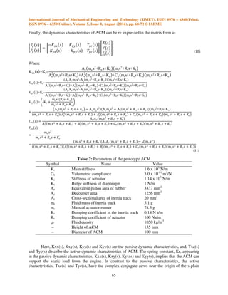
Table 3: Parameters of the electromagnetic actuator
Symbol Name Value
μ0 Absolute permeability 4 x 10⁻⁷Wb/A m
N Number of coil turns 400 turns
Imax Maximum current 4A
Ap Pole face area 268 mm2
g0 Nominal air gap 1.5mm
L Coil inductance 10 mH
R Coil resistance 4
On the other hand, the transmitted force to the chassis is also derived from the conventional
model in Fig. 6 as [10, 15]. Note that the assumption of Tyc(s) =Y(s) = 0 in Eq. (10) reduces to Eq.
(12):
/ - 0
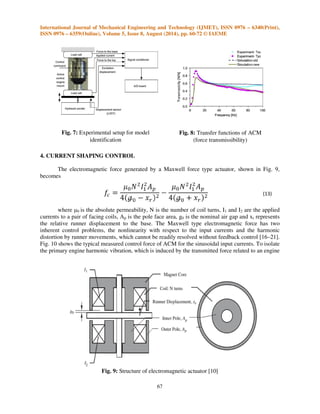
An experimental apparatus for measurement of dynamic characteristic of ACM is shown in
Fig. 7, where the test ACM is installed on a computer controlled servo-hydraulic actuation system
(INSTRON dynamic material testing system, model 8502). The excitation displacement, which
simulates the engine and chassis vibrations, is measured by an LVDT. The two load cells that are
installed at the top and bottom sides of the test ACM measure the transmitted forces to the engine
and chassis. The measured displacement and force signals are fed to signal conditioners and post-processed
to compute the passive transfer functions such as Kxx(s), Kxy(s), Kyx(s) and Kyy(s) in
Eq. (10). The current to the coil of the electromagnetic actuator is also measured to calculate the
actuator control force. Then, the control force and the transmitted forces are processed to find out the
active transfer functions, Txc (s) and Tyc (s). Tables 2 and 3 show the properties of the prototype
ACM and the electromagnetic actuator, respectively. The control target of ACM is to reduce the
transmitted force to the chassis, then transmissibility between the actuator force and transmitted force
to the base, Tyc, should be mainly described by a model. However the old model, proposed by Lee
[10], calculates transmissibility of ACM with several assumptions: (1) fluid in the chamber is
incompressible, (2) transmitted force to the upper side (Fx, engine side) equals to the transmitted
force to the lower side (Fy, chassis side). With these assumptions, transmissibility of the model-old
describes only the Txc as described in Fig. 8 In the enhanced model proposed in this paper, The
assumption (2) is no longer valid for the actuator model is included in the ACM model. By this
modification of ACM model, the model-new can describe the Tyc directly as shown in Fig. 8
Comparing the old and new models, four dynamic stiffnesses of the ACM, are not much different
from each other, but the active transfer functions in Fig. 8 show significant difference, which results
essentially from the inertia effect of actuator runner. It implies that the actuator runner inertia
becomes important in design and control of actuator, particularly in calculation of the required
actuator control force. Note that the new model is adequate to predict both the passive and active
characteristics of the ACM in the design and control stage.](https://image.slidesharecdn.com/modellingandoptimizationofelectromagnetictypeactivecontrolenginemountsystem-141023073914-conversion-gate01/85/Modelling-and-optimization-of-electromagnetic-type-active-control-engine-mount-system-10-320.jpg)
![International Journal of Mechanical Engineering and Technology (IJMET), ISSN 0976 – 6340(Print),
ISSN 0976 – 6359(Online), Volume 5, Issue 8, August (2014), pp. 60-72 © IAEME
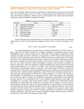
67
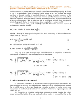
Fig. 7: Experimental setup for model
identification
4. CURRENT SHAPING CONTROL
Fig. 8: Transfer functions of ACM
(force transmissibility)
The electromagnetic force generated by a Maxwell force type actuator, shown in Fig. 9,
becomes
where μ0 is the absolute permeability, N is the number of coil turns, I1 and I2 are the applied
currents to a pair of facing coils, Ap is the pole face area, g0 is the nominal air gap and xr represents
the relative runner displacement to the base. The Maxwell type electromagnetic force has two
inherent control problems, the nonlinearity with respect to the input currents and the harmonic
distortion by runner movements, which cannot be readily resolved without feedback control [16–21].
Fig. 10 shows the typical measured control force of ACM for the sinusoidal input currents. To isolate
the primary engine harmonic vibration, which is induced by the transmitted force related to an engine
Fig. 9: Structure of electromagnetic actuator [10]](https://image.slidesharecdn.com/modellingandoptimizationofelectromagnetictypeactivecontrolenginemountsystem-141023073914-conversion-gate01/85/Modelling-and-optimization-of-electromagnetic-type-active-control-engine-mount-system-11-320.jpg)
![International Journal of Mechanical Engineering and Technology (IJMET), ISSN 0976 – 6340(Print),
ISSN 0976 – 6359(Online), Volume 5, Issue 8, August (2014), pp. 60-72 © IAEME
speed, actuator has to generate the desired harmonic force of the corresponding frequency. As shown
in Fig. 10, the actuator force due to the harmonic current input is not of a pure harmonic type, but its
waveform is distorted, resulting in undesired vibrations of higher harmonics transmitted to the
chassis. Input shaping is a well-known technique in vibration control of structures and robots, which
effectively suppresses the motion-induced vibration of structure, especially the residual vibrations of
structures and manipulators. The technique can also be used for the harmonic force generation of
actuator by properly shaping the input command signal using the known actuator model.
68
For the harmonic force, fc(t)= F* sin(t+=), applied to the actuator runner, the equation of
actuator runner motion is given by
'
,
? @ ABC = 1 %
2
where F , and = are the magnitude, frequency and phase, respectively, of the desired harmonic
control force. Eq. (14) yields
D
'
H
EF*%(G%
I!
'$%J
ABCK L
The electromagnetic force is derived from Eq. (13) as
'R
? @ ABC = MNO'PQ
'R
STN!U' MNO'PQ
STN(U'
Using Eqs. (14)– (16), the shaped input command required to compensate for harmonic
distortion due the nonlinearity and runner movement can be derived as
VW X Y
ZABC =Z
[];^
_T
'
,
`1 %
2
;a
ABC =b c d efg d g
g d efg d eg
VW X Y
ZABC =Z
[];^
_T
'
,
`1 %
2
;a
ABC =b c d efg d g
g d efg d eghi
5. ENGINE VIBRATION ESTIMATION
To generate the control force by the actuator counter-acting to the engine-induced force, the
reference signal, the so-called anti-vibration signal, associated with the engine vibration is essential
for the ACM system. In the recent decade, the estimation techniques of engine torque using
measurement of crankshaft speed variation were introduced for improved engine diagnostics and
control [12–14].
Fig. 12 describes the estimation scheme of the main harmonic engine vibration. The engine
torque generated by ignition drives the crankshaft, whose rotation is measured by CAS at the](https://image.slidesharecdn.com/modellingandoptimizationofelectromagnetictypeactivecontrolenginemountsystem-141023073914-conversion-gate01/85/Modelling-and-optimization-of-electromagnetic-type-active-control-engine-mount-system-12-320.jpg)
![International Journal of Mechanical Engineering and Technology (IJMET), ISSN 0976 – 6340(Print),
ISSN 0976 – 6359(Online), Volume 5, Issue 8, August (2014), pp. 60-72 © IAEME
flywheel location. The dynamic combustion torque also forces the engine-mounting system to
vibrate and transmit force to the chassis. Using the force transmissibility of ACM, the transmitted
force to the chassis and thus the anti-vibration command are determined. The engine motion due to
the combustion torque can be expressed as
Te (s) = {[M]s2 + [C]s + [K]}q(s)
Fig. 12: Engine vibration estimation using CAM and CAS signal
where q ( s ) is the displacement vector of the mass center of engine given as
q(s) = [x(s) y(s) z (s)qjAqkqlAmn](https://image.slidesharecdn.com/modellingandoptimizationofelectromagnetictypeactivecontrolenginemountsystem-141023073914-conversion-gate01/85/Modelling-and-optimization-of-electromagnetic-type-active-control-engine-mount-system-13-320.jpg)

This summary provides the key details about the document in 3 sentences: The document discusses the modeling and optimization of an electromagnetic active control engine-mount system. It presents the development of a low-cost prototype active control engine mount that replaces feedback sensors with a model-based feedforward algorithm. The algorithm consists of a vibration estimation method, current shaping controller, and enhanced engine mount model to compensate for performance degradation from eliminating feedback sensors.


![[000008]](https://cdn.slidesharecdn.com/ss_thumbnails/000008-211028000724-thumbnail.jpg?width=640&height=640&fit=bounds)


![5G Explained! A High Level Overview [Introduction]](https://cdn.slidesharecdn.com/ss_thumbnails/5gexplainedahighleveloverview-260119165306-cc137a3e-thumbnail.jpg?width=640&height=640&fit=bounds)


