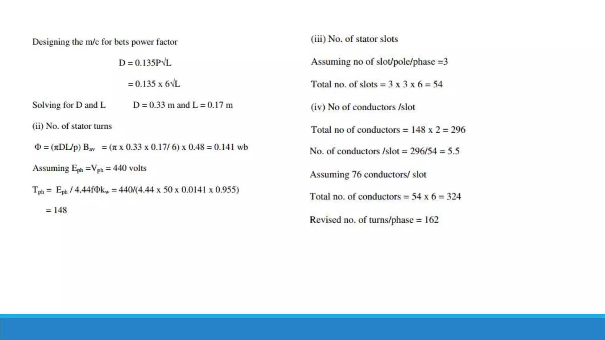
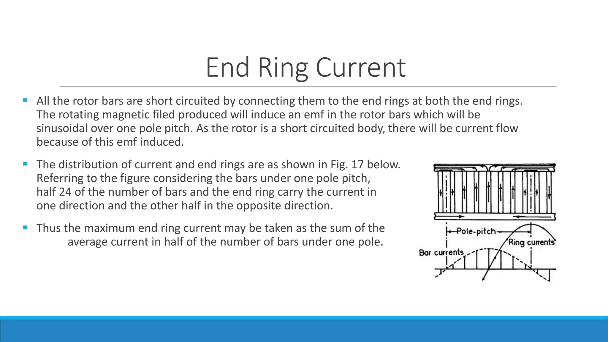
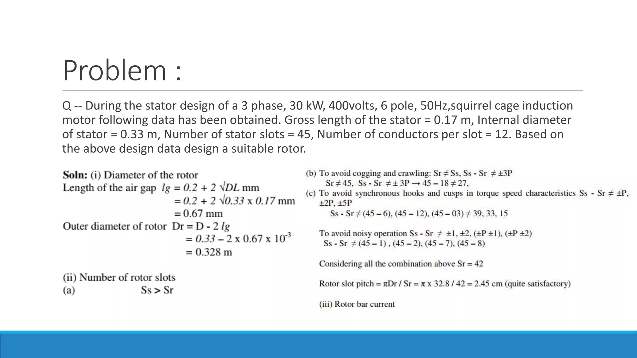
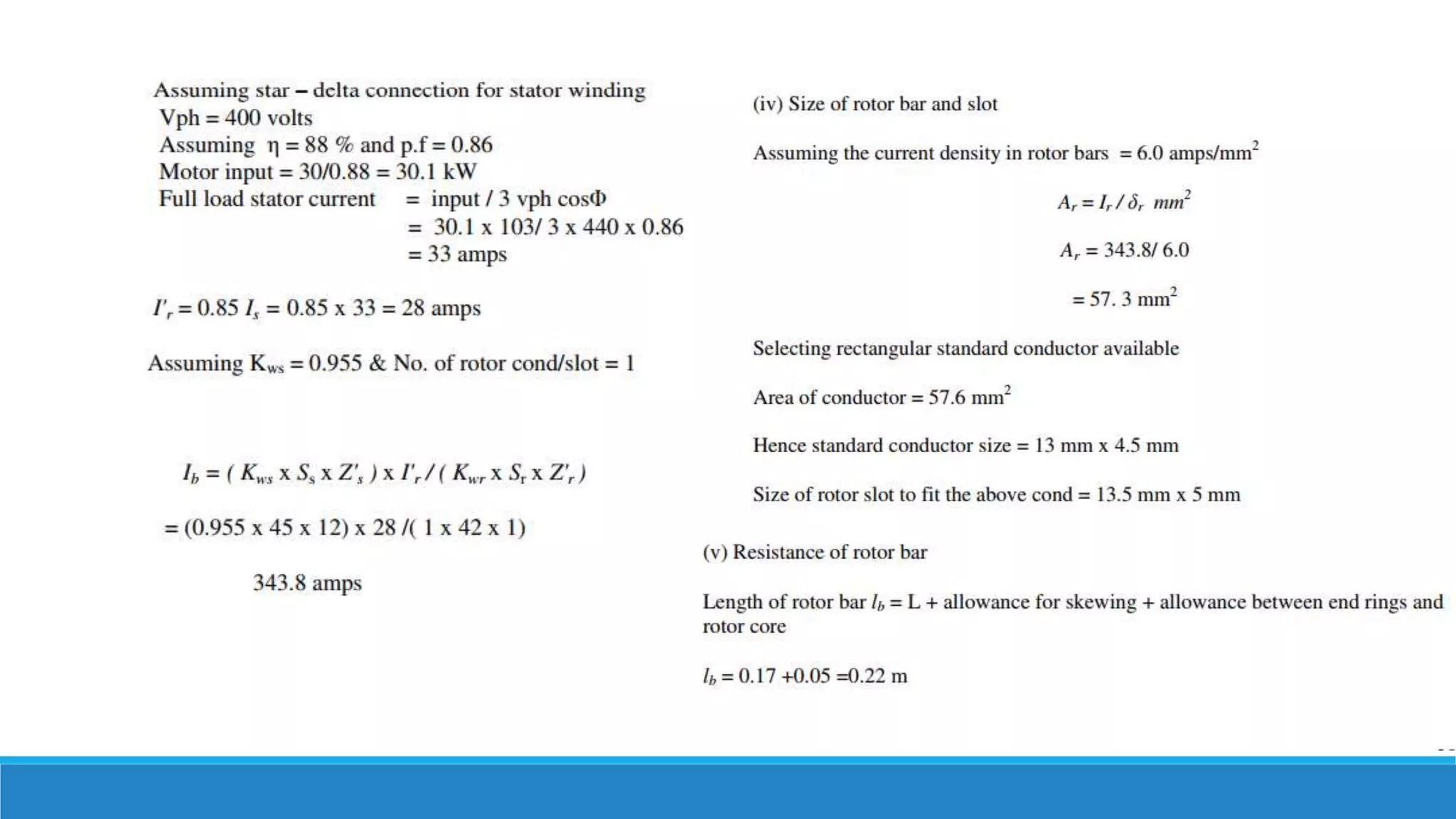
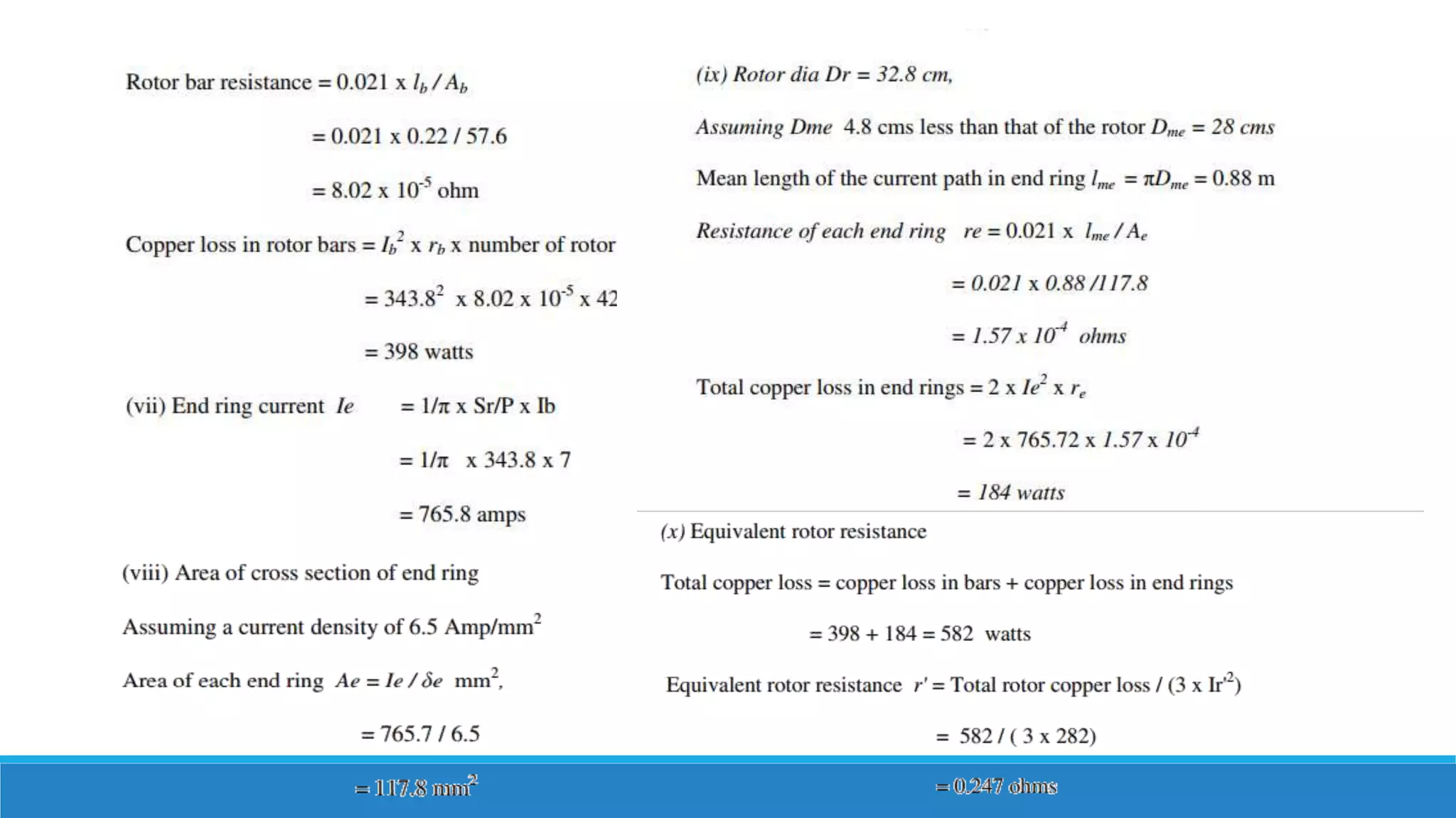
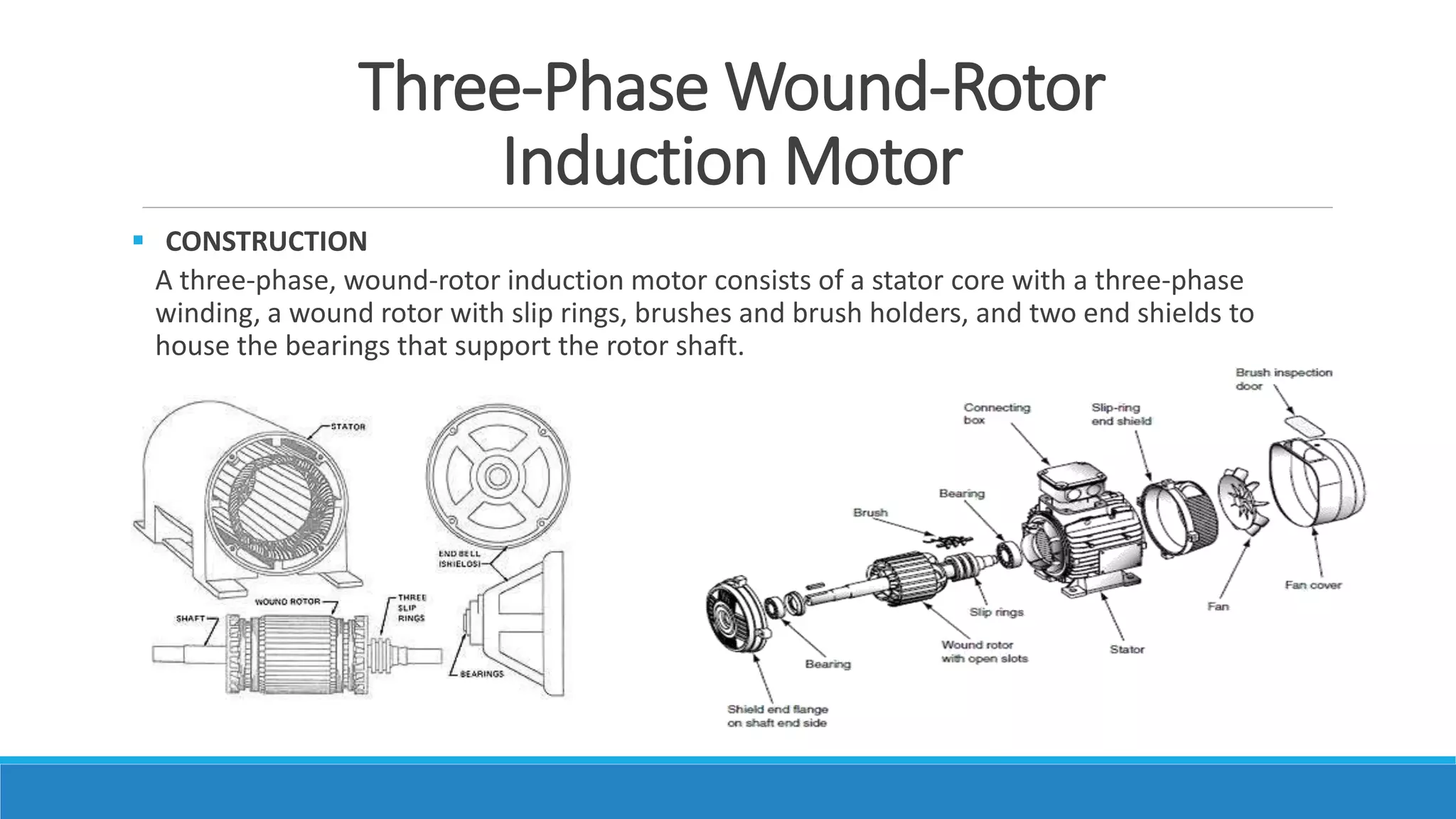
The document provides details on the design of stator and rotor slots for a 3-phase wound-rotor induction motor. It discusses the construction of the motor including the stator core and winding, wound rotor with slip rings, and end shields. For stator design, it describes slot types, selection of number of slots, conductor cross-section, slot area and size, length of mean turn and resistance calculation. For rotor design, it discusses air gap length, number of rotor slots selection to avoid crawling and cogging, end ring current, design of wound rotor including number of turns and rotor current calculation. It provides an example design problem for a 30kW squirrel cage induction motor and asks to design a suitable rotor
Synchronous machines have two sets of windings - a three-phase armature winding on the stationary stator and a DC field winding on the rotating rotor. The rotor can have either a salient pole or cylindrical structure. Large generators use brushless excitation systems to avoid maintenance issues associated with slip rings and brushes. Excitation is provided by a small AC generator (brushless exciter) mounted on the stator whose output is rectified to supply DC current to the main field winding. Proper cooling is required to dissipate heat generated in the windings.
The induction motor operates on the principle of electromagnetic induction. It consists of two main parts - the stator and the rotor. The stator contains windings that generate a rotating magnetic field, acting as the primary. This rotating field induces currents in the rotor windings, which acts as the secondary. The rotor is then pushed to rotate at a slightly lower speed than the rotating field due to "slip."
This document provides information about induction motors. It describes the basic construction of an induction motor, including its stator and squirrel cage or wound rotor. It explains how a rotating magnetic field is produced from the three-phase stator windings and how this induces a voltage and current in the rotor. It defines key terms like synchronous speed and slip. It also presents the equivalent circuit model of an induction motor and discusses speed control methods and power losses in induction machines.
The document discusses various braking methods for induction motors, including regenerative braking, plugging, and different types of dynamic braking. Regenerative braking occurs when the rotor speed exceeds synchronous speed, causing power to flow in the reverse direction. Plugging involves reversing the phase sequence of the supply to change operation from motoring to braking. Dynamic braking disconnects one phase of the supply or connects the motor to a DC supply, causing the motor to act as a generator and dissipate energy as heat.
This document discusses different types of single-phase induction motors and how they are made self-starting. It describes the construction and working of a basic single-phase induction motor. Such a motor is not self-starting because it produces an alternating flux that cannot cause rotation on its own. The document then explains various methods used to make single-phase motors self-starting, including split-phase, capacitor-start, and shaded-pole designs. It provides details on how split-phase and capacitor-start motors introduce a phase difference between windings using a starting winding and capacitor, producing a revolving magnetic field that can start the motor.
This presentation provides an overview of induction motors. It begins by defining an electric motor as a device that converts electrical energy to mechanical energy. It then classifies motors as either alternating current (AC) or direct current (DC). The presentation focuses on AC induction motors, which are the most common type used in industry due to their simple design, low cost, and ease of maintenance. It describes the basic components and operation of an induction motor, including its stator, rotor, and how rotational motion is produced through electromagnetic induction. It also discusses two common rotor types - squirrel cage and wound rotor - and defines the concept of slip in induction motors.
1) Single phase induction motors use a split phase winding or capacitor start method to generate a rotating magnetic field for starting.
2) Synchronous motors operate at a constant synchronous speed and use a damper winding, pony motor, or DC motor method to reach synchronous speed before loading.
3) V curves show the relationship between armature current, field current, and excitation voltage in synchronous motors.
This document discusses traction motors and their control. It describes the desirable characteristics of traction motors, including high starting torque, simple speed control, and self-relieving properties. It evaluates the suitability of DC series motors, AC series motors, and linear induction motors for traction applications. It also examines speed control methods for DC traction motors like series parallel control, transition methods, regenerative braking, and the self-relieving property of DC series motors. Numerical examples are provided on series parallel control and regenerative braking.
speed control of three phase induction motorAshvani Shukla
This document summarizes various methods for controlling the speed of three-phase induction motors. It discusses that induction motors are commonly used in industry due to their low cost and rugged construction but operate at constant speed. Various speed control methods are then outlined, including stator voltage control, stator frequency control, and stator current control. V/F control is also explained in detail along with its advantages for providing efficient motor speed control. The document concludes by discussing applications in industry and topics for further research.
An induction motor is described with the following specifications:
- 480-V, 60 Hz, 50-hp, 3-phase
- Drawing 60A at 0.85 PF lagging
- Stator copper losses of 2 kW
- Rotor copper losses of 700 W
To determine the rotor frequency at full load, the slip is calculated using the given power rating, current, and power factor. The slip is then used to calculate the rotor frequency.
This document discusses special electrical machines, specifically permanent magnet synchronous motors (PMSM). It describes PMSM as a brushless DC motor with permanent magnets on the rotor that create magnetic poles instead of a field winding. The document outlines the basic construction and working principle of PMSM, noting that a rotating magnetic field from the stator interacts with the permanent rotor magnets to produce torque. Applications mentioned include servo drives, robotics, traction systems, and railway transportation.
This document outlines and describes the key components and operating principles of three-phase induction motors, which are widely used in industrial applications due to their continuous operation. It discusses the main types of electrical machines and induction motors, including squirrel cage and slip ring induction motors. The document explains the basic working principle of three-phase induction motors, involving the generation of a rotating magnetic field in the stator that induces current in the rotor. It also describes the main components of three-phase induction motors such as the frame, stator, rotor, and windings.
This document contains 5 numerical problems related to analyzing the operation of three-phase induction machines. Problem 1 involves calculating various speeds, frequencies, and voltages given machine specifications operating at rated slip. Problem 2 involves calculating power values given a 3-phase induction motor's rated power and windage/friction losses. Problem 3 involves calculating starting and full-load operating values like current, slip, and efficiency given motor parameters. Problem 4 involves determining the resistance value needed in the rotor circuit to reduce the motor speed from operating at a given speed and load to a lower speed. Problem 5 involves calculating torque values from the ratio of starting to full-load rotor current.
The document discusses 3-phase induction motors. It describes how a rotating magnetic field is produced in the stator by 3-phase currents, which induces currents in the rotor and causes it to rotate. It discusses the construction of squirrel cage and wound rotors. It also covers key concepts like slip, torque production, equivalent circuits, power flow, and torque-speed characteristics of 3-phase induction motors.
The document discusses induction motors. It explains that an induction motor works by electromagnetic induction, where the alternating current in the stator produces a rotating magnetic field that induces current in the rotor and causes it to turn. It describes the basic components of induction motors including the stator, rotor, and housing. It also discusses how varying the frequency of the alternating current supply can be used to control the motor's speed.
Starting method for 3 phase induction motorAhmed A.Hassan
The document discusses four common methods for starting 3-phase induction motors: rotor resistance starting for slip-ring motors, and direct-on-line starting, star-delta starting, and autotransformer starting for squirrel-cage motors. Rotor resistance starting allows adjusting the starting torque and current by adding external resistance to the rotor circuit. Direct-on-line starting applies full supply voltage but results in high starting current and moderate starting torque. Star-delta starting and autotransformer starting both initially apply reduced voltage to lower starting current and torque before switching to full voltage.
The document discusses the construction and operation of synchronous generators. It describes how a synchronous generator works by applying a DC current to the rotor to create a rotating magnetic field, which induces a 3-phase voltage in the stator windings. It also discusses the rotor, field windings, armature windings, brushless excitation systems, equivalent circuits, phasor diagrams, and the effects of load changes on generators operating alone or connected in parallel.
The document discusses three-phase induction motors. It covers the motor's construction, basic concepts, equivalent circuit model, power and torque characteristics, and speed control. The key learning objectives are understanding the motor's construction, slip concept, equivalent circuit model, torque-speed curve variations, and speed control techniques. The motor has a stationary stator and a rotating squirrel cage or wound rotor. Voltage induced in the rotor from the rotating stator magnetic field causes current flow and torque production. The motor runs at sub-synchronous speed due to slip between the rotor and field speeds.
A reluctance motor is a type of electric motor that induces non-permanent magnetic poles on the ferromagnetic rotor. The rotor does not have any windings. It generates torque through magnetic reluctance.
Reluctance motor sub types include synchronous, variable, switched and variable stepping.
Reluctance motors can deliver high power density at low cost, making them attractive for many applications. Disadvantages include high torque ripple (the difference between maximum and minimum torque during one revolution) when operated at low speed, and noise due to torque ripple.
Physical Description
Mathematical Model
Park's "dqo" transportation
Steady-state Analysis
phasor representation in d-q coordinates
link with network equations
Definition of "rotor angle"
Representation of Synchronous Machines in Stability Studies
neglect of stator transients
magnetic saturation
Simplified Models
Synchronous Machine Parameters
Reactive Capability Limits
Consists of two sets of windings:
3 phase armature winding on the stator distributed with centres 120° apart in space
field winding on the rotor supplied by DC
Two basic rotor structures used:
salient or projecting pole structure for hydraulic units (low speed)
round rotor structure for thermal units (high speed)
Salient poles have concentrated field windings; usually also carry damper windings on the pole face.Round rotors have solid steel rotors with distributed windings
Nearly sinusoidal space distribution of flux wave shape obtained by:
distributing stator windings and field windings in many slots (round rotor);
shaping pole faces (salient pole)
The document discusses power system transients. It defines transients as pulses of very short duration but high intensity. Transients can be classified as ultra-fast, medium-fast, or slow depending on their speed. Causes of transients include lightning, switching operations, faults, and resonance. When a transmission line is energized, voltages build up gradually along it via traveling waves. The velocity and behavior of these waves are determined by the line's inductance and capacitance per unit length.
This document discusses generator protection techniques. It begins by explaining why protective systems are needed to protect expensive power system elements like generators. It then describes different types of generator faults and various protection schemes. These include stator protection using differential protection and its modifications. Rotor faults and their protections like rotor earth fault protection are also explained. The document provides details on other protections like overcurrent, overvoltage, vibration and overheating protections. It concludes by stating that protective devices help detect faults, notify maintenance, and disconnect faulty elements to ensure continuous and safe operation of power systems.
A synchronous motor operates at a constant synchronous speed determined by the supply frequency. It consists of a stator with 3-phase windings and a rotor with direct current excited poles. Synchronous motors can operate at different power factors by adjusting the rotor excitation. They are not self-starting and require an auxiliary starting method like an induction motor start or separate starting motor.
The document discusses induction motors, which are asynchronous AC motors that operate below synchronous speed. It describes the two main types - single phase and three phase induction motors. Three phase induction motors are commonly used in industry due to their ability to provide bulk power conversion from electrical to mechanical power. The document then discusses the construction and working principles of three phase induction motors in detail, including their stator, rotor, and how rotational motion is induced in the rotor via electromagnetic induction from the rotating stator magnetic field.
1. Three phase induction motors have a rotating magnetic field produced by a three phase stator winding that causes the rotor to turn.
2. The rotor can be either a squirrel cage (copper or aluminum bars short circuited by end rings) or wound construction.
3. Starters are used to reduce the starting current by lowering the supply voltage and improve starting torque by increasing rotor resistance during start up. Common starting methods include direct-on-line, star-delta, and auto transformer starters.
This document provides an overview of DC machines and motors. It discusses:
1) The fundamentals of DC generators and motors, including how voltage is induced in a conductor moving through a magnetic field and how a force is induced on a current-carrying conductor in a magnetic field.
2) The construction of DC machines, including the stationary stator with field poles and rotating armature/rotor with windings.
3) Different types of DC motors like shunt, series, and compound motors and how their field and armature windings are connected. Speed control methods for DC motors are also discussed.
4) Workings of DC motors are explained through equivalent circuits and equations for induced voltage
The document provides information on the construction and operation of a three phase induction motor. It discusses the main components of the stator and rotor. The stator contains windings and is made of laminated steel, while the rotor can be either a squirrel cage or wound type. When the stator is energized with AC voltage, it produces a rotating magnetic field that induces currents in the rotor. The interaction between these currents and the stator field produces torque that causes the rotor to rotate. The document also examines various design considerations for the motor such as the choice of specific magnetic and electric loadings, dimensions, winding configuration and core construction.
Single phase induction motor Design.pptxFaisalSheraz4
This document provides information on the construction and design of a three phase induction motor. It discusses the main components of the stator and rotor, including the laminated steel cores, windings, and squirrel cage construction. Design considerations covered include the selection of specific magnetic and electric loadings to determine dimensions, number of slots, tooth width, and air gap length. Equations are provided for calculating motor ratings and dimensions based on power, voltage, and other specifications.
The document discusses three phase induction motors. It describes the basic construction of three phase induction motors including the stator and rotor. The rotor can be either a squirrel cage type or wound type. The squirrel cage rotor is the most common due to its simple and rugged construction. The document also covers the rotating magnetic field produced by three phase currents on the stator, torque-slip characteristics, and various speed control techniques such as changing the supply voltage or frequency.
Output equation of Induction motor; Main dimensions; Separation of D and L; Choice of Average flux density; length of air gap; Design of Stator core; Rules for selecting rotor slots of squirrel cage machines; Design of rotor bars and slots; Design of end rings; Design of wound rotor; Magnetic leakage calculations; Leakage reactance of polyphase machines; Magnetizing current; Short circuit current; Operating characteristics; Losses and Efficiency.
This document provides details on the design of a turbo alternator. It includes:
1) Key parameters that must be considered in turbo alternator design such as diameter, speed, air gap length, and output equation modifications for low speed.
2) Construction details of the stator including smaller diameter, larger axial length, ventilating holes, and conductor design.
3) Methods for estimating the air gap length and length of the armature.
4) The rotor uses a smooth cylindrical non-salient pole design to prevent exceeding the safe peripheral speed limit due to high rotation.
The document provides details about the syllabus for the course 19E404 - Induction and Synchronous Machine. It discusses the key topics that will be covered including three phase induction motors, their construction, working principle, performance and control. It also discusses single phase induction motors and synchronous generators and motors, their construction and operating principles.
1. The document discusses the principle of operation of 3-phase induction motors and their applications. It explains how a rotating magnetic field is generated using a 3-phase supply, which causes the rotor to turn.
2. Key aspects covered include induction motor construction, torque-speed characteristics, multi-pole motors, and applications of variable frequency drives.
3. The document compares DC and AC machines, and explains why AC induction motors are more commonly used due to the availability of single or multi-phase AC power.
The document discusses the principles of operation of 3-phase induction motors. It explains that a 3-phase induction motor operates using a rotating magnetic field produced by a 3-phase AC current in the stator windings which causes the rotor to turn. As the rotor turns slightly slower than the rotating field, a slip is produced which generates an induced current in the rotor and produces torque. The torque causes the rotor to accelerate until the motor reaches its operating speed where the torque equals the load.
This document discusses the principle of operation of 3-phase induction motors. It explains that a 3-phase induction motor operates using a rotating magnetic field produced by a 3-phase AC current in the stator windings which causes the rotor to turn. As the rotor turns slightly slower than the rotating magnetic field, a slip is produced which induces currents in the rotor windings to generate torque. The torque causes the rotor to accelerate until the motor reaches its operating speed where the torque exactly balances the mechanical load on the shaft.
The document discusses the principles of operation of 3-phase induction motors. It explains that a 3-phase induction motor operates using a rotating magnetic field produced by a 3-phase AC current in the stator windings which causes the rotor to turn. The speed of the rotor is slightly less than the synchronous speed of the rotating magnetic field due to slip. The difference between the rotor speed and synchronous speed is used to produce torque. Torque-speed characteristics and power output equations for 3-phase induction motors are also presented.
The document discusses various methods for starting 3-phase induction motors. It describes five main methods: 1) direct-on-line starting, 2) stator resistance starting, 3) autotransformer starting, 4) star-delta starting, and 5) rotor resistance starting. Direct-on-line starting applies full voltage at start and is suitable for small motors. Stator resistance and autotransformer starting reduce starting voltage to limit current. Star-delta switching changes the winding configuration. Rotor resistance starting adds external resistors in the rotor circuit for slip ring motors.
Synchonous machine design selection of no of slotsAjay Balar
The document discusses factors to consider when selecting the number of slots in an electric machine, including:
1. The number of slots affects cost and performance, with more slots providing advantages like reduced leakage reactance and better cooling but also disadvantages like increased cost and weaker teeth.
2. Key considerations for slot selection include slot loading being less than 1500A/slot, slot pitch limitations based on voltage, and selecting 3-4 or 7-9 slots per pole per phase for salient pole and turbo alternator machines.
3. Other factors discussed are tooth width, slot width, depth, and insulation to ensure proper space for conductors and prevent excessive flux density in teeth.
The document summarizes key aspects of alternator construction and operation. It describes:
1) The main components of an alternator including the stationary stator with 3-phase winding and rotating rotor with DC field winding. Two common rotor types are salient pole and smooth cylindrical.
2) Armature and field windings, including single vs. double layer windings and full vs. short pitch windings.
3) Synchronizing and parallel operation which allows multiple alternators to run in unison by matching voltage, frequency, and phase sequence.
4) Synchronizing current, power, and torque which occur during the matching process prior to paralleling alternators.
1. The document discusses synchronous machines, including their construction, types of prime movers, and excitation systems. It describes salient pole and cylindrical rotors, as well as different winding configurations like distributed, integral slot, and fractional windings.
2. Hydro turbines and diesel engines typically drive synchronous machines with salient pole rotors, while steam turbines drive higher speed machines with cylindrical rotors. Excitation systems can be DC, static using thyristors, or brushless.
3. The document provides an overview of synchronous machines and their components.
The document discusses induction motors and their operation. It begins by explaining that induction motors operate using induction rather than direct conduction of power to the rotor like in DC motors. The rotor receives power through induction in the same way as a transformer secondary from the primary. Induction motors can thus be viewed as rotary transformers. The rotor is then induced to spin by the revolving magnetic field produced by the three-phase stator winding when powered. Two main types of rotors are described: squirrel cage, which is the simplest design; and wound rotor, which allows adding external resistance to control torque.
The document discusses three-phase induction motors, including their construction, operation, and characteristics. It describes:
1) The main components of three-phase induction motors are the stator, which contains three-phase windings, and the rotor, which is either a squirrel cage or wound type. The rotating magnetic field in the stator induces currents in the rotor that generate torque.
2) Induction motors operate at a speed slightly below synchronous speed, with the difference called slip. Torque output is proportional to slip at low slip values and decreases with increasing slip above a maximum point.
3) Key motor characteristics like starting torque, maximum torque, equivalent circuits, and torque-slip curves are explained
Similar to Design of stator & rotor for Wound Induction Motor (20)
Power Quality Measurement Devices & MonotoringParth Patel
Power quality measurement devices are used to monitor voltage, current, harmonics, and disturbances on electrical systems. Common devices include harmonic analyzers to measure harmonic distortion, transient analyzers to capture short-duration events, oscilloscopes for high-frequency waveforms, and data loggers for long-term steady-state monitoring. Proper instrument selection depends on factors like the number of measurement channels, voltage and current measurement capabilities, and analysis software.
Impacts of Distributed Generation on Power QualityParth Patel
This paper studies the impacts of distributed generation, specifically solar and wind power, on power quality when interconnected to a distribution utility feeder. Multiple scenarios were modeled and simulated using the RSCAD/RTDS real-time simulation tool. The results show some increase in harmonic distortion and voltage fluctuations with the addition of distributed generation, but within acceptable limits. Harmonics were observed at higher orders which could impact power quality. Voltage fluctuations increased nearer to the distributed generation sources.
Factors to be considered while selecting CTParth Patel
The document discusses key factors to consider when selecting current transformers (CTs). It covers:
- CT functions such as supplying protective relays with proportional currents and isolating measuring devices from high voltages.
- Principles such as magnetic flux inducing proportional secondary currents and high current transformation ratios.
- Types including bar, wound, and window types based on construction and measuring vs protective functions.
- Additional factors like accuracy class, knee-point voltage, burden, short-time current rating, and accuracy limit factor which influence performance during faults. Proper consideration of these factors is important for specifying CTs suited for an application's requirements.
Basic Industrial Instruments Used for Flow measurnment.
Working , Construction and diagrams with detailed explanations.
Major type of Instruments are listed.
An alternator is an electrical generator that converts mechanical energy to electrical energy. It uses a rotating magnetic field with a stationary armature. The working principle relies on Faraday's law of electromagnetic induction. As the armature rotates within the magnetic field, an alternating current is produced. The main components are the stator with stationary armature windings and the rotor with a rotating magnetic field supplied by a DC current. Armature reaction causes the magnetic field to be distorted by the armature current. Alternators have various applications including in automobiles, power plants, and for providing regenerative braking in induction motors. Induction generators can also be used to convert the rotational energy of windmills into electrical energy.
The Presentation represents one of the electromagnatic effect on transmission line (The skin effect), other being the proximity effect.
The Following topics are covered :
1.Defination
2,Cause
3.Formula
4.Skin Depth
5.Mitigation Techniques.
This document discusses different types of air compressors. It describes reciprocating compressors which use pistons driven by crankshafts to compress air in cylinders. It also describes rotary compressors like centrifugal compressors which use rapidly spinning impellers to accelerate and compress air, and axial compressors which use alternating rows of fixed and moving blades to compress air. The document also discusses positive displacement compressors like roots blowers which use interleaving lobes to trap and compress air, and vane compressors which use sliding vanes and an eccentric rotor to vary chamber volumes and compress air.
Using recycled concrete aggregates (RCA) for pavements is crucial to achieving sustainability. Implementing RCA for new pavement can minimize carbon footprint, conserve natural resources, reduce harmful emissions, and lower life cycle costs. Compared to natural aggregate (NA), RCA pavement has fewer comprehensive studies and sustainability assessments.
TIME DIVISION MULTIPLEXING TECHNIQUE FOR COMMUNICATION SYSTEMHODECEDSIET
Time Division Multiplexing (TDM) is a method of transmitting multiple signals over a single communication channel by dividing the signal into many segments, each having a very short duration of time. These time slots are then allocated to different data streams, allowing multiple signals to share the same transmission medium efficiently. TDM is widely used in telecommunications and data communication systems.
### How TDM Works
1. **Time Slots Allocation**: The core principle of TDM is to assign distinct time slots to each signal. During each time slot, the respective signal is transmitted, and then the process repeats cyclically. For example, if there are four signals to be transmitted, the TDM cycle will divide time into four slots, each assigned to one signal.
2. **Synchronization**: Synchronization is crucial in TDM systems to ensure that the signals are correctly aligned with their respective time slots. Both the transmitter and receiver must be synchronized to avoid any overlap or loss of data. This synchronization is typically maintained by a clock signal that ensures time slots are accurately aligned.
3. **Frame Structure**: TDM data is organized into frames, where each frame consists of a set of time slots. Each frame is repeated at regular intervals, ensuring continuous transmission of data streams. The frame structure helps in managing the data streams and maintaining the synchronization between the transmitter and receiver.
4. **Multiplexer and Demultiplexer**: At the transmitting end, a multiplexer combines multiple input signals into a single composite signal by assigning each signal to a specific time slot. At the receiving end, a demultiplexer separates the composite signal back into individual signals based on their respective time slots.
### Types of TDM
1. **Synchronous TDM**: In synchronous TDM, time slots are pre-assigned to each signal, regardless of whether the signal has data to transmit or not. This can lead to inefficiencies if some time slots remain empty due to the absence of data.
2. **Asynchronous TDM (or Statistical TDM)**: Asynchronous TDM addresses the inefficiencies of synchronous TDM by allocating time slots dynamically based on the presence of data. Time slots are assigned only when there is data to transmit, which optimizes the use of the communication channel.
### Applications of TDM
- **Telecommunications**: TDM is extensively used in telecommunication systems, such as in T1 and E1 lines, where multiple telephone calls are transmitted over a single line by assigning each call to a specific time slot.
- **Digital Audio and Video Broadcasting**: TDM is used in broadcasting systems to transmit multiple audio or video streams over a single channel, ensuring efficient use of bandwidth.
- **Computer Networks**: TDM is used in network protocols and systems to manage the transmission of data from multiple sources over a single network medium.
### Advantages of TDM
- **Efficient Use of Bandwidth**: TDM all
Introduction- e - waste – definition - sources of e-waste– hazardous substances in e-waste - effects of e-waste on environment and human health- need for e-waste management– e-waste handling rules - waste minimization techniques for managing e-waste – recycling of e-waste - disposal treatment methods of e- waste – mechanism of extraction of precious metal from leaching solution-global Scenario of E-waste – E-waste in India- case studies.
ACEP Magazine edition 4th launched on 05.06.2024Rahul
This document provides information about the third edition of the magazine "Sthapatya" published by the Association of Civil Engineers (Practicing) Aurangabad. It includes messages from current and past presidents of ACEP, memories and photos from past ACEP events, information on life time achievement awards given by ACEP, and a technical article on concrete maintenance, repairs and strengthening. The document highlights activities of ACEP and provides a technical educational article for members.
KuberTENes Birthday Bash Guadalajara - K8sGPT first impressionsVictor Morales
K8sGPT is a tool that analyzes and diagnoses Kubernetes clusters. This presentation was used to share the requirements and dependencies to deploy K8sGPT in a local environment.
A review on techniques and modelling methodologies used for checking electrom...nooriasukmaningtyas
The proper function of the integrated circuit (IC) in an inhibiting electromagnetic environment has always been a serious concern throughout the decades of revolution in the world of electronics, from disjunct devices to today’s integrated circuit technology, where billions of transistors are combined on a single chip. The automotive industry and smart vehicles in particular, are confronting design issues such as being prone to electromagnetic interference (EMI). Electronic control devices calculate incorrect outputs because of EMI and sensors give misleading values which can prove fatal in case of automotives. In this paper, the authors have non exhaustively tried to review research work concerned with the investigation of EMI in ICs and prediction of this EMI using various modelling methodologies and measurement setups.
Understanding Inductive Bias in Machine LearningSUTEJAS
This presentation explores the concept of inductive bias in machine learning. It explains how algorithms come with built-in assumptions and preferences that guide the learning process. You'll learn about the different types of inductive bias and how they can impact the performance and generalizability of machine learning models.
The presentation also covers the positive and negative aspects of inductive bias, along with strategies for mitigating potential drawbacks. We'll explore examples of how bias manifests in algorithms like neural networks and decision trees.
By understanding inductive bias, you can gain valuable insights into how machine learning models work and make informed decisions when building and deploying them.
New techniques for characterising damage in rock slopes.pdf
Design of stator & rotor for Wound Induction Motor
1. Design Of Stator & Rotor slot 3 Phase Wound
Motor
Subject : Design of AC Machines
2. Three-Phase Wound-Rotor
Induction Motor
CONSTRUCTION
A three-phase, wound-rotor induction motor consists of a stator core with a three-phase
winding, a wound rotor with slip rings, brushes and brush holders, and two end shields to
house the bearings that support the rotor shaft.
3. The Stator
A typical stator contains a three-phase winding held in place in the slots of a laminated steel core, figure 2. The
winding consists of formed coils arranged and connected so that there are three single-phase windings spaced
120 electrical degrees apart. The separate single-phase windings are connected either in wye or delta. Three
line leads are brought out to a terminal box mounted on the frame of the motor. This is the same construction
as the squirrel-cage motor stator.
4. The Rotor
The rotor consists of a cylindrical core composed of steel laminations. Slots cut into the cylindrical core hold the
formed coils of wire for the rotor winding.
The rotor winding consists of three single-phase windings spaced 120 electrical degrees apart. The single-phase
windings are connected either in wye or delta. (The rotor winding must have the same number of poles as the stator
winding.)
5. PRINCIPLE OF OPERATION
When three currents, 120 electrical degrees apart, pass through the three single-phase windings in
the slots of the stator core, a rotating magnetic field is developed. This field travels around the stator.
The speed of the rotating field depends on the number of stator poles and the frequency of the
power source. This speed is called the synchro nous speed. It is determined by applying the formula
which was used to find the synchro nous speed of the rotating field of squirrel-cage induction motors.
Synchronous speed in RPM = [120 x frequency in hertz / number of poles] or S =120 x F / P
S= 120 x f/P
As the rotating field travels at synchronous speed, it cuts the three-phase winding of the rotor
and induces voltages in this winding. The rotor winding is connected to the three slip rings mounted
on the rotor shaft. The brushes riding on the slip rings connect to an external wye-connected group of
resistors (speed controller), figure 5. The induced voltages in the rotor windings set up currents which
follow a closed path from the rotor winding to the wye-connected speed controller. The rotor
currents create a magnetic fieldin the rotor core based on transformer action. This rotor field reacts
with the stator field to develop the torque which causes the rotor to turn. The speed controller is
sometimes called the secondary resistance control.
6. Design of Stator
Stator slots: in general two types of stator slots are employed in induction motors viz, open
clots and semiclosed slots. Operating performance of the induction motors depends upon the
shape of the slots and hence it is important to select suitable slot for the stator slots.
◦ (i) Open slots: In this type of slots the slot opening will be equal to that of the width of the slots as
shown in Fig 10. In such type of slots assembly and repair of winding are easy. However such slots will
lead to higher air gap contraction factor and hence poor power factor. Hence these types of slots are
rarely used in 3Φ induction motors.
◦ (ii) Semiclosed slots: In such type of slots, slot opening is much smaller than the width of the slot as
shown in Fig 10 and Fig 11. Hence in this type of slots assembly of windings is more difficult and takes
more time compared to open slots and hence it is costlier. However the air gap characteristics are better
compared to open type slots.
◦ (iii) Tapered slots: In this type of slots also, opening will be much smaller than the slot width. However
the slot width will be varying from top of the slot to bottom of the slot with minimum width at the
bottom as shown in Fig. 10.
7.
8. Selection of number of stator slots
Number of stator slots must be properly selected at the design stage as such this number affects the
weight, cost and operating characteristics of the motor. Though there are no rules for selecting the number
of stator slots considering the advantages and disadvantages of selecting higher number slots comprise has
to be set for selecting the number of slots. Following are the advantages and disadvantages of selecting
higher number of slots.
Advantages :
(i) Reduced leakage reactance.
(ii) Reduced tooth pulsation losses.
(iii) Higher over load capacity.
Disadvantages:
(i) Increased cost
(ii) (ii) Increased weight
(iii) (iii) Increased magnetizing current
(iv) Increased iron losses
(v) Poor cooling
(vi) Increased temperature rise
(vii) Reduction in efficiency
9. Conductor cross section
Area of cross section of stator conductors can be estimated from the stator current per phase
and suitably assumed value of current density for the stator windings.
Sectional area of the stator conductor as = Is / δs where δs is the current density in stator
windings
Stator current per phase Is = Q / (3Vph cosФ)
Based on the sectional area shape and size of the conductor can be decided. If the sectional
area of the conductors is below 5 mm2 then usually circular conductors are employed. If it is
above 5 mm2 then rectangular conductors will be employed. S
10. Area of stator slot:
Slot area is occupied by the conductors and the insulation. Out of which almost more than 25
% is the insulation.
Once the number of conductors per slot is decided approximate area of the slot can be
estimated.
Slot space factor = Copper area in the slot /Area of each slot .
This slot space factor so obtained will be between 0.25 and 0.4. The detailed dimension of the
slot can be estimated as follows.
11. Size of the slot
Normally different types of slots are employed for carrying stator
windings of induction motors. Generally full pitched double layer
windings are employed for stator windings.
For double layer windings the conductor per slot will be even. These
conductors are suitably arranged along the depth and width of the
winding. Stator slots should not be too wide, leading to thin tooth
width, which makes the tooth mechanically weak and maximum flux
density may exceed the permissible limit.
Hence slot width should be so selected such that the flux density in
tooth is between 1.6 to 1.8 Tesla. Further the slots should not be too
deep also other wise the leakage reactance increases.
As a guideline the ratio of slot depth to slot width may assumed as 3
to 5. Slot insulation details along the conductors are shown in Fig
12. Length of the mean Turn
&
Resistance of stator winding
Length of the mean turn is calculated using an empirical formula
lmt = 2L + 2.3 τp + 0.24
where L is the gross length of the stator and τp is pole pitch in meter.
Resistance of the stator winding per phase is calculated using the formula = (0.021 x lmt x Tph )
/ as where lmt is in meter and as is in mm2 . Using so calculated resistance of stator winding
copper losses in stator winding can be calculated as
Total copper losses in stator winding = 3 (Is) 2 rs
13. Problems :
Q-- Obtain the following design information for the stator of a 30 kW, 440 V, 3Φ, 6 pole, 50 Hz
delta connected, squirrel cage induction motor, (i) Main dimension of the stator, (ii) No. of
turns/phase (iii) No. of stator slots, (iv) No. of conductors per slot. Assume suitable values for
the missing design data.
14.
15. Design of Rotor
Between stator and rotor is the air gap which is a very critical part. The performance
parameters of the motor like magnetizing current, power factor, over load capacity, cooling and
noise are affected by length of the air gap. Hence length of the air gap is selected considering
the advantages and disadvantages of larger air gap length.
Advantages:
(i) Increased overload capacity
(ii) Increased cooling
(iii) Reduced unbalanced magnetic pull
(iv) Reduced in tooth pulsation
(v) Reduced noise
Disadvantages
(i) Increased Magnetising current
(ii) (ii) Reduced power factor
16. Crawling & Cogging
The rotating magnetic field produced in the air gap of the
will be usually nonsinusoidal and generally contains odd
harmonics of the order 3rd, 5th and 7th. The third
harmonic flux will produce the three times the magnetic
poles compared to that of the fundamental.
Similarly the 5th and 7th harmonics will produce the
poles five and seven times the fundamental respectively.
The presence of harmonics in the flux wave affects the
torque speed characteristics.
The 7th harmonics will produce a dip in torque speed
characteristics at one seventh of its normal speed as
shown in torque speed characteristics.
In some cases where in the number of rotor slots
are not proper in relation to number of stator slots
the machine refuses to run and remains stationary.
Under such conditions there will be a locking
tendency between the rotor and stator. Such a
phenomenon is called cogging.
Hence in order to avoid such bad effects a proper
number of rotor slots are to be selected in relation
to number of stator slots.
In addition rotor slots will be skewed by one slot
pitch to minimize the tendency of cogging, torque
defects like synchronous hooks and cusps and
noisy operation while running. Effect of skewing
will slightly increase the rotor resistance and
increases the starting torque.
17. Selection of number of rotor slots
The number of rotor slots may be selected using the following guide lines.
(i) To avoid cogging and crawling: (a)Ss ≠ Sr (b) Ss - Sr ≠ ±3P
(ii) To avoid synchronous hooks and cusps in torque speed characteristics ≠ ±P, ±2P, ±5P.
(iii) To noisy operation Ss - Sr ≠ ±1, ±2, (±P ±1), (±P ±2)
18. End Ring Current
All the rotor bars are short circuited by connecting them to the end rings at both the end rings.
The rotating magnetic filed produced will induce an emf in the rotor bars which will be
sinusoidal over one pole pitch. As the rotor is a short circuited body, there will be current flow
because of this emf induced.
The distribution of current and end rings are as shown in Fig. 17 below.
Referring to the figure considering the bars under one pole pitch,
half 24 of the number of bars and the end ring carry the current in
one direction and the other half in the opposite direction.
Thus the maximum end ring current may be taken as the sum of the
average current in half of the number of bars under one pole.
19. Design of wound Rotor
These are the types of induction motors where in rotor also carries distributed star connected 3 phase
winding. At one end of the rotor there are three slip rings mounted on the shaft. Three ends of the winding
are connected to the slip rings.
External resistances can be connected to these slip rings at starting, which will be inserted in series with the
windings which will help in increasing the torque at starting. Such type of induction motors are employed
where high starting torque is required.
Number of rotor slots: As mentioned earlier the number of rotor slots should never be equal to number of
stator slots. Generally for wound rotor motors a suitable value is assumed for number of rotor slots per pole
per phase, and then total number of rotor slots are calculated. So selected number of slots should be such
that tooth width must satisfy the flux density limitation. Semiclosed slots are used for rotor slots.
20. Number of rotor Turns:
Number of rotor turns are decided based on the safety consideration of the personal working with the
induction motors. The volatge between the slip rings on open circuit must be limited to safety values.
In general the voltage between the slip rings for low and medium voltage machines must be limited to
400 volts. For motors with higher voltage ratings and large size motors this voltage must be limited to
1000 volts. Based on the assumed voltage between the slip rings comparing the induced voltage ratio
in stator and rotor the number of turns on rotor winding can be calculated.
21. Rotor Current
Rotor current can be calculated by comparing the amp-cond on stator and rotor
22. Problem :
Q -- During the stator design of a 3 phase, 30 kW, 400volts, 6 pole, 50Hz,squirrel cage induction
motor following data has been obtained. Gross length of the stator = 0.17 m, Internal diameter
of stator = 0.33 m, Number of stator slots = 45, Number of conductors per slot = 12. Based on
the above design data design a suitable rotor.