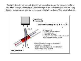
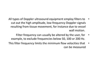
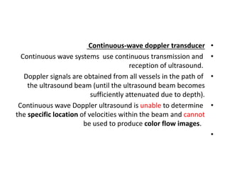
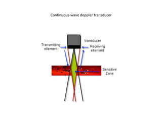
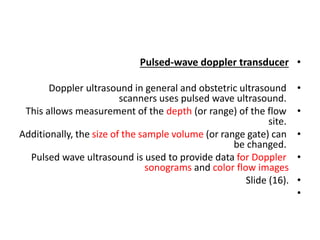
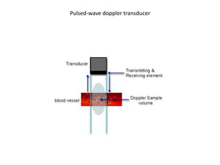
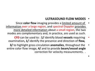
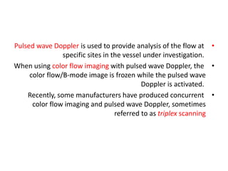
DOPPLER US (2)
Dr. Kamal Sayed MSc US UAA
dopp principles/ guidelines/Velocity measurement/
dopp TXR types/aliasing/flow modes
•
DOPPPLER US PRINCIPLES & PRACTICE GUIDLINE
•
What is the principle of ultrasound?
•
An electric current passes through a cable to the transducer
and is applied to the crystals, causing them to deform and
vibrate. This vibration produces the ultrasound beam. The
frequency of the ultrasound waves produced is
predetermined by the crystals in the transducer.
•
Competent use of Doppler ultrasound techniques requires an
understanding of three key components:
•
(1) The capabilities and limitations of Doppler ultrasound;
(2) The different parameters which contribute to the flow
display;
(3) Blood flow in arteries and veins.
•
This chapter describes how these components contribute to
the quality of Doppler ultrasound images.
•
Guidelines are given on how to obtain good images in all flow
imaging modes.
•
Ultrasound images of flow, whether color flow or spectral
Doppler, are essentially obtained from measurements of
movement.
•
In ultrasound scanners, a series of pulses is transmitted to
detect movement of blood.
•
Echoes from stationary tissue are the same from pulse to
pulse.
•
•
Echoes from moving scatterers exhibit slight differences in the
time for the signal to be returned to the receiver
•
These differences can be measured as a direct time difference
or, more usually, in terms of a phase shift from which the
‘Doppler frequency’ is obtained
•
They are then processed to produce either a color flow
display or a Doppler sonogram
•
slide (6/7)
•
.
Figure 1 Ultrasound velocity measurement. The diagram shows a scatterer S moving at velocity V
with a beam/flow angle q.
The velocity can be calculated by the difference in transmit-to-receive time from the first pulse to
the second (t2), as the scatterer moves through the beam.
Figure 2: Doppler ultrasound. Doppler ultrasound measures the movement of the
scatterers through the beam as a phase change in the received signal. The resulting
Doppler frequency can be used to measure velocity if the beam/flow angle is known.
•
if the flow is perpendicular to the beam, there is NO relative
motion from pulse to pulse.
•
The size of the Doppler signal is dependent on:
•
(1) Blood velocity: as velocity increases, so does the Doppler
frequency;
(2) Ultrasound frequency: higher ultrasound frequencies give
increased Doppler frequency. (As in B-mode, lower ultrasound
frequencies have better penetration).
(3) The choice of frequency: is a compromise between better
sensitivity to flow or better penetration;
•
(4 The angle of insonation: the Doppler frequency increases
as the Doppler ultrasound beam becomes more aligned to the
flow direction (the angle q between the beam and the
direction of flow becomes smaller). This is of the utmost
importance in the use of Doppler ultrasound
•
. The implications are illustrated schematically
in slide (10)
•
Effect of the Doppler angle in the sonogram (A) higher-frequency Doppler signal is obtained if the beam is
aligned more to the direction of flow. In the diagram, beam (A) is more ali)gned than (B) and produces higher-
frequency Doppler signals. The beam/flow angle at (C) is almost 90° and there is a very poor Doppler signal.
The flow at (D) is away from the beam and there is a negative signal.
.
•
All types of Doppler ultrasound equipment employ filters to
cut out the high amplitude, low-frequency Doppler signals
resulting from tissue movement, for instance due to vessel
wall motion.
•
Filter frequency can usually be altered by the user, for
example, to exclude frequencies below 50, 100 or 200 Hz.
•
This filter frequency limits the minimum flow velocities that
can be measured
•
Continuous-wave doppler transducer
•
Continuous wave systems use continuous transmission and
reception of ultrasound.
•
Doppler signals are obtained from all vessels in the path of
the ultrasound beam (until the ultrasound beam becomes
sufficiently attenuated due to depth).
•
Continuous wave Doppler ultrasound is unable to determine
the specific location of velocities within the beam and cannot
be used to produce color flow images.
•
•
Relatively inexpensive Doppler ultrasound systems are
available which employ continuous wave probes to give
Doppler output without the addition of B-mode images.
•
Continuous wave Doppler is also used in adult cardiac
scanners to investigate the high velocities in the aorta.
•
Slide (14)
Continuous-wave doppler transducer
•
Pulsed-wave doppler transducer
•
Doppler ultrasound in general and obstetric ultrasound
scanners uses pulsed wave ultrasound.
•
This allows measurement of the depth (or range) of the flow
site.
•
Additionally, the size of the sample volume (or range gate) can
be changed.
•
Pulsed wave ultrasound is used to provide data for Doppler
sonograms and color flow images
•
Slide (16).
•
Pulsed-wave doppler transducer
•
ULTRASOUND FLOW MODES
•
Since color flow imaging provides a limited amount of
information over a large region, and spectral Doppler provides
more detailed information about a small region, the two
modes are complementary and, in practice, are used as such.
•
CFD can be used to : 1/ identify blood vessels requiring
examination, 1/ identify the presence and direction of flow,
•
3/ to highlight gross circulation anomalies, throughout the
entire color flow image, 4/ and to provide beam/vessel angle
correction for velocity measurements. .
•
•
Pulsed wave Doppler is used to provide analysis of the flow at
specific sites in the vessel under investigation.
•
When using color flow imaging with pulsed wave Doppler, the
color flow/B-mode image is frozen while the pulsed wave
Doppler is activated.
•
Recently, some manufacturers have produced concurrent
color flow imaging and pulsed wave Doppler, sometimes
referred to as triplex scanning
•
when these modes are used simultaneously, the performance
of each is decreased.
•
Because transducer elements are employed in three modes
(B-mode, color flow and pulsed wave Doppler):,
•
@ The frame rate is decreased,
•
@ The color flow box is reduced in size
•
@ and the available pulse repetition frequency is reduced,
leading to increased susceptibility to aliasing.
•
•
The magnitude of the color flow output is displayed rather
than the Doppler frequency signal.
•
Power Doppler does not display flow direction or different
velocities.
•
It is often used in conjunction with frame averaging to
increase sensitivity to low flows and velocities. It
complements the other two modes. Hybrid color flow modes
incorporating power and velocity data are also available from
some manufacturers. .
•
•
Power Doppler is also referred to as energy Doppler,
amplitude Doppler and Doppler angiography.
•
These can also have improved sensitivity to low flow.
•
A brief summary of factors influencing the displays in each
mode is given in the following sections.
•
Most of these factors are set up approximately for a particular
mode when the application (e.g. fetal scan) is chosen,
although the operator will usually alter many of the controls
during the scan to optimize the image
•
Spectral Doppler
•
1- Examines flow at one site
•
2- Detailed analysis of distribution of flow
•
3- Good temporal resolution – can examine flow waveform
•
4- Allows calculations of velocity and indices
•
Color flow
•
1- Overall view of flow in a region
•
2- Limited flow information
•
3- Poor temporal resolution/flow dynamics (frame rate can be
low when scanning deep)
•
4- color flow map (diferent color maps)
•
5- direction information
•
6- velocity information (high velocity & low velocity)
•
7- turbulent flows
•
Power/energy/amplitude flow
•
1- Sensitive to low flows
•
2- No directional information in some modes
•
3- Very poor temporal resolution
•
4- Susceptible to noise
"Color Power Angio" of the Circle of Willis
"Color Power Angio" of a submucosus fibroid, note the small vessels inside
the tumor.
•
Color flow imaging (Color flow Doppler) ultrasound produces
a color-coded map of Doppler shifts superimposed onto a B-
mode ultrasound image (Color Flow Maps).
•
Although color flow imaging uses pulsed wave ultrasound, its
processing differs from that used to provide the Doppler
sonogram.
•
•
Color flow imaging may have to produce several thousand
color points of flow information for each frame superimposed
on the B-mode image. Color flow imaging uses fewer, shorter
pulses along each color scan line of the image to give a mean
frequency shift and a variance at each small area of
measurement. This frequency shift is displayed as a color
pixel.
•
The scanner then repeats this for several lines to build up the
color image, which is superimposed onto the B-mode image.
The transducer elements are switched rapidly between B-
mode and color flow imaging to give an impression of a
combined simultaneous image.
•
The pulses used for color flow imaging are typically three to
four times longer than those for the B-mode image, with a
corresponding loss of axial resolution.
•
Assignment of color to frequency shifts is usually based on
@direction (for example, red for Doppler shifts towards the
ultrasound beam and blue for shifts away from it) and
@magnitude : a) different color hues b) or lighter saturation
for higher frequency shifts).
•
The color Doppler image is dependent on general Doppler
factors, particularly the need for a good beam/flow angle.
•
. Curvilinear and phased array transducers have a radiating
pattern of ultrasound beams that can produce complex color
flow images, depending on the orientation of the arteries and
veins. In practice, the experienced operator alters the
scanning approach to obtain good insonation angles so as to
achieve unambiguous flow images.
Doppler us (2)

Doppler us (2)

  • 1.
    DOPPLER US (2) Dr.Kamal Sayed MSc US UAA dopp principles/ guidelines/Velocity measurement/ dopp TXR types/aliasing/flow modes
  • 2.
    • DOPPPLER US PRINCIPLES& PRACTICE GUIDLINE • What is the principle of ultrasound? • An electric current passes through a cable to the transducer and is applied to the crystals, causing them to deform and vibrate. This vibration produces the ultrasound beam. The frequency of the ultrasound waves produced is predetermined by the crystals in the transducer.
  • 3.
    • Competent use ofDoppler ultrasound techniques requires an understanding of three key components: • (1) The capabilities and limitations of Doppler ultrasound; (2) The different parameters which contribute to the flow display; (3) Blood flow in arteries and veins. • This chapter describes how these components contribute to the quality of Doppler ultrasound images. • Guidelines are given on how to obtain good images in all flow imaging modes.
  • 4.
    • Ultrasound images offlow, whether color flow or spectral Doppler, are essentially obtained from measurements of movement. • In ultrasound scanners, a series of pulses is transmitted to detect movement of blood. • Echoes from stationary tissue are the same from pulse to pulse. •
  • 5.
    • Echoes from movingscatterers exhibit slight differences in the time for the signal to be returned to the receiver • These differences can be measured as a direct time difference or, more usually, in terms of a phase shift from which the ‘Doppler frequency’ is obtained • They are then processed to produce either a color flow display or a Doppler sonogram • slide (6/7) • .
  • 6.
    Figure 1 Ultrasoundvelocity measurement. The diagram shows a scatterer S moving at velocity V with a beam/flow angle q. The velocity can be calculated by the difference in transmit-to-receive time from the first pulse to the second (t2), as the scatterer moves through the beam.
  • 7.
    Figure 2: Dopplerultrasound. Doppler ultrasound measures the movement of the scatterers through the beam as a phase change in the received signal. The resulting Doppler frequency can be used to measure velocity if the beam/flow angle is known.
  • 8.
    • if the flowis perpendicular to the beam, there is NO relative motion from pulse to pulse. • The size of the Doppler signal is dependent on: • (1) Blood velocity: as velocity increases, so does the Doppler frequency; (2) Ultrasound frequency: higher ultrasound frequencies give increased Doppler frequency. (As in B-mode, lower ultrasound frequencies have better penetration). (3) The choice of frequency: is a compromise between better sensitivity to flow or better penetration;
  • 9.
    • (4 The angleof insonation: the Doppler frequency increases as the Doppler ultrasound beam becomes more aligned to the flow direction (the angle q between the beam and the direction of flow becomes smaller). This is of the utmost importance in the use of Doppler ultrasound • . The implications are illustrated schematically in slide (10) •
  • 10.
    Effect of theDoppler angle in the sonogram (A) higher-frequency Doppler signal is obtained if the beam is aligned more to the direction of flow. In the diagram, beam (A) is more ali)gned than (B) and produces higher- frequency Doppler signals. The beam/flow angle at (C) is almost 90° and there is a very poor Doppler signal. The flow at (D) is away from the beam and there is a negative signal. .
  • 11.
    • All types ofDoppler ultrasound equipment employ filters to cut out the high amplitude, low-frequency Doppler signals resulting from tissue movement, for instance due to vessel wall motion. • Filter frequency can usually be altered by the user, for example, to exclude frequencies below 50, 100 or 200 Hz. • This filter frequency limits the minimum flow velocities that can be measured
  • 12.
    • Continuous-wave doppler transducer • Continuouswave systems use continuous transmission and reception of ultrasound. • Doppler signals are obtained from all vessels in the path of the ultrasound beam (until the ultrasound beam becomes sufficiently attenuated due to depth). • Continuous wave Doppler ultrasound is unable to determine the specific location of velocities within the beam and cannot be used to produce color flow images. •
  • 13.
    • Relatively inexpensive Dopplerultrasound systems are available which employ continuous wave probes to give Doppler output without the addition of B-mode images. • Continuous wave Doppler is also used in adult cardiac scanners to investigate the high velocities in the aorta. • Slide (14)
  • 14.
  • 15.
    • Pulsed-wave doppler transducer • Dopplerultrasound in general and obstetric ultrasound scanners uses pulsed wave ultrasound. • This allows measurement of the depth (or range) of the flow site. • Additionally, the size of the sample volume (or range gate) can be changed. • Pulsed wave ultrasound is used to provide data for Doppler sonograms and color flow images • Slide (16). •
  • 16.
  • 17.
    • ULTRASOUND FLOW MODES • Sincecolor flow imaging provides a limited amount of information over a large region, and spectral Doppler provides more detailed information about a small region, the two modes are complementary and, in practice, are used as such. • CFD can be used to : 1/ identify blood vessels requiring examination, 1/ identify the presence and direction of flow, • 3/ to highlight gross circulation anomalies, throughout the entire color flow image, 4/ and to provide beam/vessel angle correction for velocity measurements. . •
  • 18.
    • Pulsed wave Doppleris used to provide analysis of the flow at specific sites in the vessel under investigation. • When using color flow imaging with pulsed wave Doppler, the color flow/B-mode image is frozen while the pulsed wave Doppler is activated. • Recently, some manufacturers have produced concurrent color flow imaging and pulsed wave Doppler, sometimes referred to as triplex scanning
  • 19.
    • when these modesare used simultaneously, the performance of each is decreased. • Because transducer elements are employed in three modes (B-mode, color flow and pulsed wave Doppler):, • @ The frame rate is decreased, • @ The color flow box is reduced in size • @ and the available pulse repetition frequency is reduced, leading to increased susceptibility to aliasing.
  • 20.
    • • The magnitude ofthe color flow output is displayed rather than the Doppler frequency signal. • Power Doppler does not display flow direction or different velocities. • It is often used in conjunction with frame averaging to increase sensitivity to low flows and velocities. It complements the other two modes. Hybrid color flow modes incorporating power and velocity data are also available from some manufacturers. . •
  • 21.
    • Power Doppler isalso referred to as energy Doppler, amplitude Doppler and Doppler angiography. • These can also have improved sensitivity to low flow. • A brief summary of factors influencing the displays in each mode is given in the following sections. • Most of these factors are set up approximately for a particular mode when the application (e.g. fetal scan) is chosen, although the operator will usually alter many of the controls during the scan to optimize the image
  • 22.
    • Spectral Doppler • 1- Examinesflow at one site • 2- Detailed analysis of distribution of flow • 3- Good temporal resolution – can examine flow waveform • 4- Allows calculations of velocity and indices
  • 23.
    • Color flow • 1- Overallview of flow in a region • 2- Limited flow information • 3- Poor temporal resolution/flow dynamics (frame rate can be low when scanning deep) • 4- color flow map (diferent color maps) • 5- direction information • 6- velocity information (high velocity & low velocity) • 7- turbulent flows
  • 24.
    • Power/energy/amplitude flow • 1- Sensitiveto low flows • 2- No directional information in some modes • 3- Very poor temporal resolution • 4- Susceptible to noise
  • 25.
    "Color Power Angio"of the Circle of Willis
  • 26.
    "Color Power Angio"of a submucosus fibroid, note the small vessels inside the tumor.
  • 27.
    • Color flow imaging(Color flow Doppler) ultrasound produces a color-coded map of Doppler shifts superimposed onto a B- mode ultrasound image (Color Flow Maps). • Although color flow imaging uses pulsed wave ultrasound, its processing differs from that used to provide the Doppler sonogram. •
  • 28.
    • Color flow imagingmay have to produce several thousand color points of flow information for each frame superimposed on the B-mode image. Color flow imaging uses fewer, shorter pulses along each color scan line of the image to give a mean frequency shift and a variance at each small area of measurement. This frequency shift is displayed as a color pixel.
  • 29.
    • The scanner thenrepeats this for several lines to build up the color image, which is superimposed onto the B-mode image. The transducer elements are switched rapidly between B- mode and color flow imaging to give an impression of a combined simultaneous image. • The pulses used for color flow imaging are typically three to four times longer than those for the B-mode image, with a corresponding loss of axial resolution.
  • 30.
    • Assignment of colorto frequency shifts is usually based on @direction (for example, red for Doppler shifts towards the ultrasound beam and blue for shifts away from it) and @magnitude : a) different color hues b) or lighter saturation for higher frequency shifts). • The color Doppler image is dependent on general Doppler factors, particularly the need for a good beam/flow angle.
  • 31.
    • . Curvilinear andphased array transducers have a radiating pattern of ultrasound beams that can produce complex color flow images, depending on the orientation of the arteries and veins. In practice, the experienced operator alters the scanning approach to obtain good insonation angles so as to achieve unambiguous flow images.