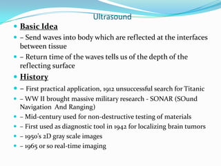
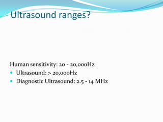
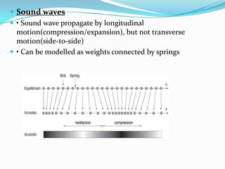
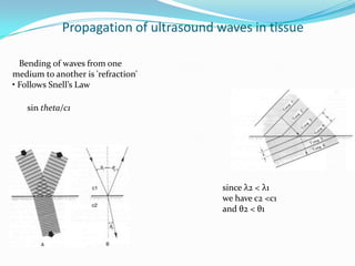
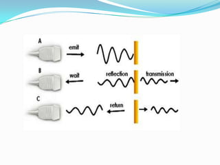
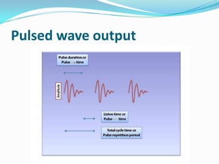
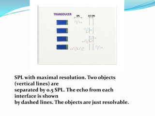
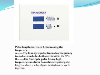
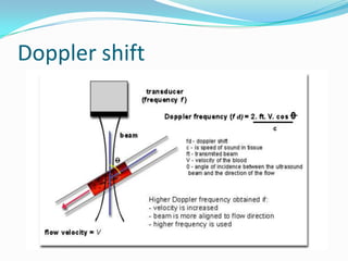
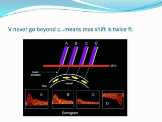
Russian Call Girls in Pune Tanvi 9907093804 Short 1500 Night 6000 Best call g...
ULTRASOUND IMAGING PRINCIPLES
1.
2. SEMINAR
ON
ULTRASOUND
Tharanath PP
India Ultrasound
3. Ultrasound
Basic Idea
– Send waves into body which are reflected at the interfaces
between tissue
– Return time of the waves tells us of the depth of the
reflecting surface
History
– First practical application, 1912 unsuccessful search for Titanic
– WW II brought massive military research - SONAR (SOund
Navigation And Ranging)
– Mid-century used for non-destructive testing of materials
– First used as diagnostic tool in 1942 for localizing brain tumors
– 1950’s 2D gray scale images
– 1965 or so real-time imaging
5. Sound waves
• Sound wave propagate by longitudinal
motion(compression/expansion), but not transverse
motion(side-to-side)
• Can be modelled as weights connected by springs
6. Specular - echoes originating from relatively large,
regularly shaped objects with smooth surfaces. These
echoes are relatively intense and angle dependent.
(i.e.valves) - Reflection from large surfaces
Scattered - echoes originating from relatively small,
weakly reflective, irregularly shaped objects are less angle
dependant and less intense. (i.e.. blood cells) -Reflection
from small surfaces
7. Along each line we transmit a pulse and plot the
reflections that come back vs time
9. Propagation of ultrasound waves in
tissue
Propagation of ultrasound waves in tissue
• Ultrasound imaging systems
commonly operate at 3.5
MHz, which corresponds to a
wavelength of 0.44 mm
when c = 1540 m/s.
Refraction
• When a wave passes from
one medium to another the
frequency is constant, and
since c changes then so
must the wavelength
10. Propagation of ultrasound waves in tissue
Bending of waves from one
medium to another is 'refraction'
• Follows Snell’s Law
sin theta/c1
since λ2 < λ1
we have c2 <c1
and θ2 < θ1
11. Definition/ Terminology
Cycle
Frequency: cycles per second
Wave length
Period
Amplitude
Compression - area of high density
Rarefication - area of low density
velocity = l x ƒ= constant for a given medium
13. Ultrasound Production
Piezoelectric effect:
– Crystals vibrate at given frequency when an
alternating current is applied
– Crystal acts as speaker and microphone
Continuous mode:
– continuous-wave Doppler (CW)
Pulsed-echo mode:
15. there is no information about the time interval from
the signal to the reflection, and, hence, no information
about the depth of the received signal; the signal may
come from any depth. The continuous Doppler has no
Nykvist limit, and can measure maximal velocities. It
is used for measuring high velocities.
16. Pulsed Echo
Signal generation = only ~1% of the entire
pulse cycle
On times; off times
Time of signal return proportional to distance
travelled
17. if the PRF = 5 kHz and the time between pulses is
0.2 msec, it will take 0.1 msec to reach the target
and 0.1 msec to return to the transducer. This means
the pulse will travel 15.4 cm before the next pulse is
emitted (1,540 m/sec x 0.1 msec = 0.154 m in 0.1
msec = 15.4 cm).
20. Pulsed Echo
PRF: pulse repetition frequency
– Very important in Color Doppler
SPL: spatial pulse length
= wavelength x no. of cycles
Maximal resolution = 0.5 SPL
– The smallest distance between 2 points that
USG can delineate
21. SPL with maximal resolution. Two objects
(vertical lines) are
separated by 0.5 SPL. The echo from each
interface is shown
by dashed lines. The objects are just resolvable.
22. Pulse length shortened by increasing the
frequency.
A ........The four-cycle pulse from a low-frequency
transducer includes both objects within the SPL.
B .........The four-cycle pulse from a high-
frequency transducer has a shorter spatial pulse
length and can resolve objects located more closely
together.
27. the main principle is that blood has high velocity
(Typically above 50 cm/s, although also all velocities
down to zero), but low density, resulting in low
intensity (amplitude) reflected signals.
Tissue has high density, resulting in high intensity
signals, but low velocity (typically below 20 cm/s).
28. The pulsed modus results in a practical limit on the
maximum velocity that can be measured. In order to
measure velocity at a certain depth, the next pulse
cannot be sent out before the signal is returned. The
Doppler shift is thus sampled once for every pulse that
is transmitted, and the sampling frequency is thus
equal to the pulse repetition frequency (PRF).
Frequency aliasing occurs at a Doppler shift that is
equal to half of the PRF.
fD = ½ * PRF
29. Sampling from increasing depth will increase the time
for the pulse returning, thus increasing the sampling
interval and decrease the sampling frequency. The
Nykvist limit thus decreases with depth. This means
that pulsed Doppler has depth resolution, but this
leads to a limit to the velocities that can be measured.
30. Ultrasound Transmission
1540 m/s– Velocity assumed the same for all tissue in
calculation (which is not totally true)
Acoustic impedance
Attenuation
Reflection
Refraction
Scatter: objects irregular or smaller than the
ultrasound beam
31. Resolution
Ability to delineate between two different
objects
Axial resolution:
– high frequency
= shorter SPL
= better axial resolution but lower penetration
32. Resolution
Lateral Resolution
– Sound beam: width of the crystal
– Near field
– Focal zone: best lateral resolution
– Far field
– Dead zone: distance between the transducer
face and the first identifiable echo
33. Resolution
Temporal Resolution
– Frame per second
– Multiple focal zones
• decreases frame rate
• decrease temporal resolution
35. Modes
A mode: amplitude
B mode: brightness
Real time (frames/sec)
M mode: motion
36. A-Scan Presentation.
The A-scan presentation displays the amount of
received ultrasonic energy as a
function of time. The relative amount of received
energy is plotted along the
vertical axis and the elapsed time (which may be
related to the sound energy
travel time within the material) is displayed along the
horizontal axis
37. B-Scan Presentation.
The B-scan presentation is a profile (cross-sectional)
view of the test specimen.
In the B-scan, the time-of-flight (travel time) of the
sound energy is displayed
along the vertical axis and the linear position of the
transducer is displayed along
the horizontal axis
38. Doppler Ultrasound
Continuous wave (CW)
– Seldom used, not a/v in most AED machines
Pulsed wave (PW)
Color Doppler
Duplex Doppler:– Putting Color Doppler on
top of Grey-scale Bmode
Power Doppler
41. Transducers
Mechanical Probe: seldom used now
Electronic Probe:
– Linear array transducers
• piezoelectric elements linearly arranged
• sequentially activated to produce an image
– Phased array transducers
• smaller scanning surface (foot print)
• good for echocardiography
• more expensive
• elements are activated with phase differences to
allow steering of the ultrasound signal
46. The Logiq 100 PRO's five main probes:
5.0 MHz Convex-Array probe, 40 mm radius, 68°
field of view
3.5 MHz Convex-Array probe, 50 mm radius, 68°
field of view
7.5 MHz Linear-Array probe, 60 mm field of view
3.5 MHz Micro convex Cardiac probe, 13 mm
radius, 82° field of view
6.5 MHz Endocavity probe, 10 mm radius, 120° field
of view
48. Contd..
Operating modes: B-Mode, Dual B-Image (B/B-
Mode), B/M Mode, M-Mode
Dimensions: 276 mm x 244 mm x 405 mm, Weight:
9.8 kg (without probes)