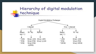
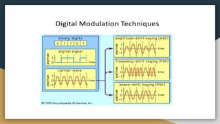
This document discusses different types of digital modulation techniques. It begins by defining modulation as the process of modifying characteristics of a high frequency carrier signal using a low frequency information signal. The key types of digital modulation covered are:
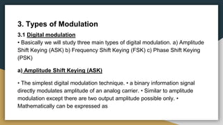
1) Amplitude Shift Keying (ASK) which modifies the amplitude of the carrier based on the binary input signal.
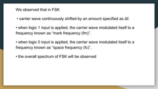
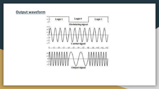
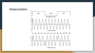
2) Frequency Shift Keying (FSK) which shifts the frequency of the carrier between two frequencies (mark and space) depending on the binary input.
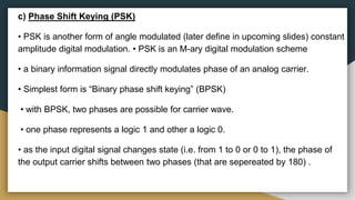
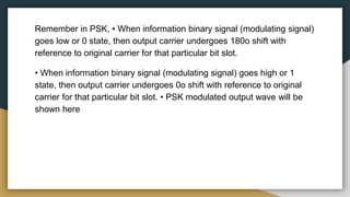
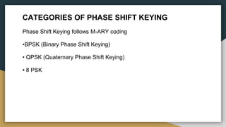
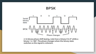
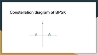
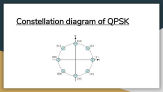
3) Phase Shift Keying (PSK) which shifts the phase of the carrier by 180 degrees depending on the binary input state for Binary PSK, and by multiple phase shifts for techniques like Quadrature P


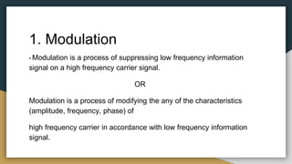
![VASK(t) = [ 1 + Vm(t)] [ (Ac/2) cos(ωct) ]
Where • VASK(t) = Amplitude Shift Keying Modulated wave • Vm(t) = Amplitude
of binary modulating (information) signal • (Ac/2) = Amplitude of un-modulated
high frequency carrier • ωc = 2πfc = un-modulated high frequency carrier.
a) Amplitude Shift Keying (ASK)
Vm (t) = logic 1 = +1V Vm (t) = logic 0 = -1V
VASK(t) = [ 1 + Vm(t)] [ (Ac/2) cos(ωct) ] VASK(t) = [ 1 + Vm(t)] [ (Ac/2) cos(ωct)]
= [ 1 +1] [ (Ac/2) cos(ωct) ] = [ 1 - 1] [ (Ac/2) cos(ωct) ]
= [2] [ (Ac/2) cos(ωct) ] = [0] [ (Ac/2) cos(ωct) ]
= [Ac cos(ωct) ] =0](https://image.slidesharecdn.com/digitalmodulationtechniques-190329114848/85/Digital-modulation-techniques-8-320.jpg)
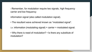
![Conclusion:
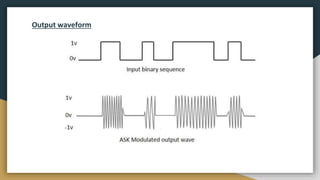
• As information signal is of binary format, only two voltage levels occur
at input (either +1V or -1V) • As a result, we get only two voltage levels
at output (either [Ac cos(ωct) ] or OV) • because of these two output
voltage levels, the carrier is either in “ON” or “OFF” state. • that’s the
reason why ASK is also known as “ON-OFF Keying (OOK)”](https://image.slidesharecdn.com/digitalmodulationtechniques-190329114848/85/Digital-modulation-techniques-10-320.jpg)
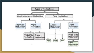
![b) Frequency Shift Keying (FSK)
• Simple and low performance type of digital modulation. • a binary information
signal directly modulates frequency of an analog carrier.
• Mathematically can be expressed as
VFSK(t) = Vc cos[ 2π (fc + Vm(t)Δf)t ]
Where • VFSK(t) = Frequency Shift Keying Modulated wave • fc = Analog carrier
central frequency • Vc = peak analog carrier amplitude • Vm(t) = binary input
(modulating) signal • Δf = peak change (shift) in the analog carrier frequency](https://image.slidesharecdn.com/digitalmodulationtechniques-190329114848/85/Digital-modulation-techniques-11-320.jpg)
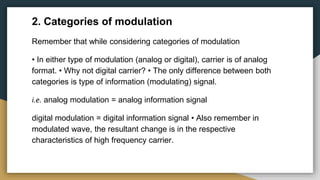
![Vm(t) = logic 1 = +1V Vm(t) = logic 1 = -1V
VFSK(t) = Vc cos[ 2π (fc + Vm(t)Δf)t ] VFSK(t) = Vc cos[ 2π (fc + Vm(t)Δf)t ]
= Vc cos[ 2π (fc + 1.Δf)t ] = Vc cos[ 2π (fc - 1.Δf)t ]
= Vc cos[ 2π (fc + Δf)t ] = Vc cos[ 2π (fc - Δf)t ]](https://image.slidesharecdn.com/digitalmodulationtechniques-190329114848/85/Digital-modulation-techniques-12-320.jpg)