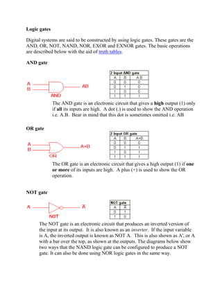
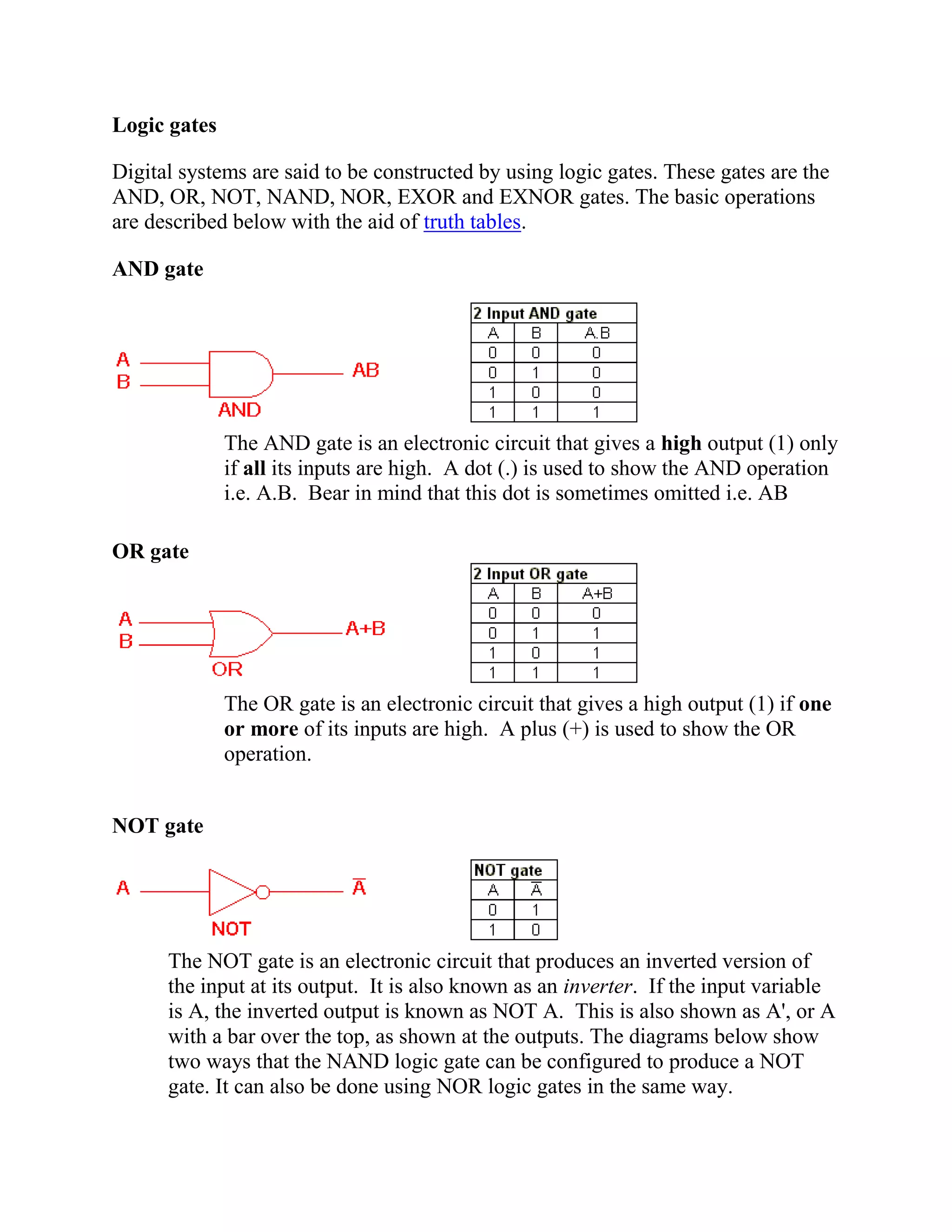
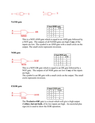
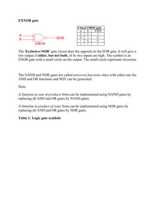
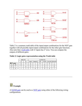
1. Logic gates
Digital systems are said to be constructed by using logic gates. These gates are the
AND, OR, NOT, NAND, NOR, EXOR and EXNOR gates. The basic operations
are described below with the aid of truth tables.
AND gate
The AND gate is an electronic circuit that gives a high output (1) only
if all its inputs are high. A dot (.) is used to show the AND operation
i.e. A.B. Bear in mind that this dot is sometimes omitted i.e. AB
OR gate
The OR gate is an electronic circuit that gives a high output (1) if one
or more of its inputs are high. A plus (+) is used to show the OR
operation.
NOT gate
The NOT gate is an electronic circuit that produces an inverted version of
the input at its output. It is also known as an inverter. If the input variable
is A, the inverted output is known as NOT A. This is also shown as A', or A
with a bar over the top, as shown at the outputs. The diagrams below show
two ways that the NAND logic gate can be configured to produce a NOT
gate. It can also be done using NOR logic gates in the same way.
2. NAND gate
This is a NOT-AND gate which is equal to an AND gate followed by
a NOT gate. The outputs of all NAND gates are high if any of the
inputs are low. The symbol is an AND gate with a small circle on the
output. The small circle represents inversion.
NOR gate
This is a NOT-OR gate which is equal to an OR gate followed by a
NOT gate. The outputs of all NOR gates are low if any of the inputs
are high.
The symbol is an OR gate with a small circle on the output. The small
circle represents inversion.
EXOR gate
The 'Exclusive-OR' gate is a circuit which will give a high output
if either, but not both, of its two inputs are high. An encircled plus
sign ( ) is used to show the EOR operation.
3. EXNOR gate
The 'Exclusive-NOR' gate circuit does the opposite to the EOR gate. It will give a
low output if either, but not both, of its two inputs are high. The symbol is an
EXOR gate with a small circle on the output. The small circle represents inversion.
The NAND and NOR gates are called universal functions since with either one the
AND and OR functions and NOT can be generated.
Note:
A function in sum of products form can be implemented using NAND gates by
replacing all AND and OR gates by NAND gates.
A function in product of sums form can be implemented using NOR gates by
replacing all AND and OR gates by NOR gates.
Table 1: Logic gate symbols
4. Table 2 is a summary truth table of the input/output combinations for the NOT gate
together with all possible input/output combinations for the other gate functions.
Also note that a truth table with 'n' inputs has 2n
rows. You can compare the
outputs of different gates.
Table 2: Logic gates representation using the Truth table
Example
A NAND gate can be used as a NOT gate using either of the following wiring
configurations.