Downloaded 26 times

![Addressing modes:
Addressing modes are nothing but the different ways in which the
location of an operand can be specified in an instruction. The number of
addressing modes that a processor supports changes according to the
instruction set it is based on, however there are a few generic ones that
are present in almost all processors and are thus of utmost importance.
They are as follows:
• register (or register-direct) addressing: R1
• register indirect addressing: M[R1]
• immediate addressing: data
• direct (or absolute) addressing: M[address]
• indirect addressing: M[M[address]]
• implicit addressing: default location
• relative & indexed addressing: M[R1+address]
• pre-decrement, post-decrement, pre-increment, ...
Register(or register-direct)Addressing:
• The operand is specified with in one of the processor register.
• Instruction specifies the register in which the operand is stored.
Example:](https://image.slidesharecdn.com/addressing-161127155835/85/Different-types-of-Addressing-cao-2-320.jpg)
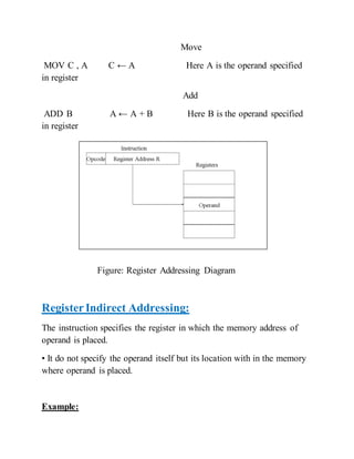
![Move
MOV A , M A ← [[H][L]]
It moves the data from memory location specified by HL register pair to
A
Figure: Register Indirect Addressing Diagram
Immediate Addressing:
The operand is specified with in the instruction.
• Operand itself is provided in the instruction rather than its address.
Example:
Move Immediate
MVI A , 15h A ← 15h
Here 15h is the immediate operand
Add Immediate](https://image.slidesharecdn.com/addressing-161127155835/85/Different-types-of-Addressing-cao-4-320.jpg)
![ADI 3Eh A ← A + 3Eh
Here 3Eh is the immediate operand
Figure: Immediate Addressing Diagram
Direct (or absolute)addressing:
• The instruction specifies the direct address of the operand.
• The memory address is specified where the actual operand is.
Example:
Load Accumulator
LDA 2805h A ← [2805]
It loads the data from memory location 2805 to A.
Store Accumulator
STA 2803h [2803] ← A
It stores the data from A to memory location 2803.](https://image.slidesharecdn.com/addressing-161127155835/85/Different-types-of-Addressing-cao-5-320.jpg)
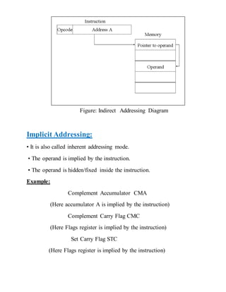
![Figure: Direct Addressing Diagram
Indirect Addressing:
• The instruction specifies the indirect address where the effective
address of the operand is placed.
• The memory address is specified where the actual address of operand
is placed.
Example:
Move
MOV A, 2802h A ← [[2802]]
It moves the data from memory location specified by the
location 2802 to A.](https://image.slidesharecdn.com/addressing-161127155835/85/Different-types-of-Addressing-cao-6-320.jpg)
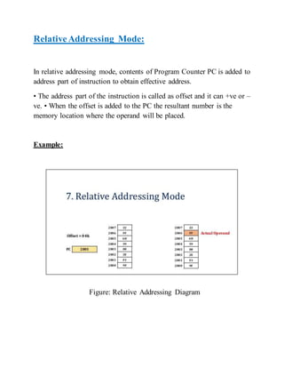
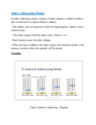
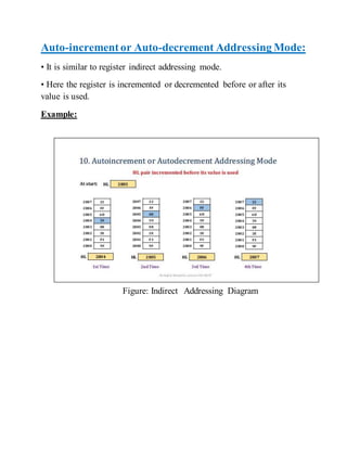

The document discusses different types of addressing modes used in computer architecture. It describes register addressing, register indirect addressing, immediate addressing, direct addressing, indirect addressing, implicit addressing, relative addressing, indexed addressing, and auto-increment/decrement addressing. Addressing modes specify the location of operands in instructions in different ways, such as using registers, memory addresses, or implicit values. Understanding addressing modes is important as different instruction sets and processors support various modes.