Instruction Set
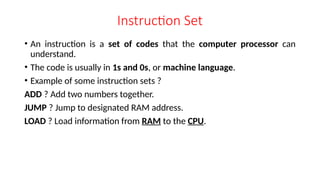
• Aninstruction is a set of codes that the computer processor can
understand.
• The code is usually in 1s and 0s, or machine language.
• Example of some instruction sets ?
ADD ? Add two numbers together.
JUMP ? Jump to designated RAM address.
LOAD ? Load information from RAM to the CPU.
3.
Instruction Type
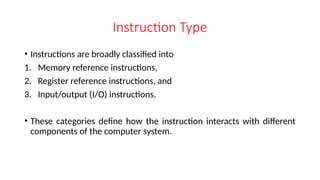
• Instructionsare broadly classified into
1. Memory reference instructions,
2. Register reference instructions, and
3. Input/output (I/O) instructions.
• These categories define how the instruction interacts with different
components of the computer system.
4.
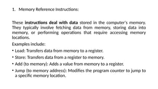
1. Memory ReferenceInstructions:
These instructions deal with data stored in the computer's memory.
They typically involve fetching data from memory, storing data into
memory, or performing operations that require accessing memory
locations.
Examples include:
• Load: Transfers data from memory to a register.
• Store: Transfers data from a register to memory.
• Add (to memory): Adds a value from memory to a register.
• Jump (to memory address): Modifies the program counter to jump to
a specific memory location.
5.
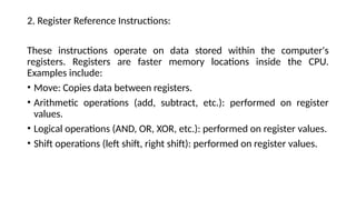
2. Register ReferenceInstructions:
These instructions operate on data stored within the computer's
registers. Registers are faster memory locations inside the CPU.
Examples include:
• Move: Copies data between registers.
• Arithmetic operations (add, subtract, etc.): performed on register
values.
• Logical operations (AND, OR, XOR, etc.): performed on register values.
• Shift operations (left shift, right shift): performed on register values.
6.
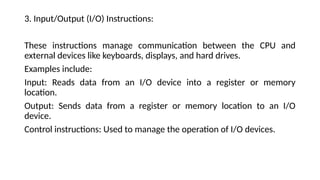
3. Input/Output (I/O)Instructions:
These instructions manage communication between the CPU and
external devices like keyboards, displays, and hard drives.
Examples include:
Input: Reads data from an I/O device into a register or memory
location.
Output: Sends data from a register or memory location to an I/O
device.
Control instructions: Used to manage the operation of I/O devices.
7.
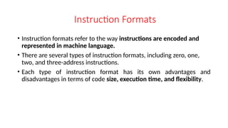
Instruction Formats
• Instructionformats refer to the way instructions are encoded and
represented in machine language.
• There are several types of instruction formats, including zero, one,
two, and three-address instructions.
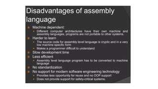
• Each type of instruction format has its own advantages and
disadvantages in terms of code size, execution time, and flexibility.
8.
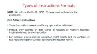
Types of InstructionsFormats
NOTE: We will use the X = (A+B)*(C+D) expression to showcase the
procedure.
Zero Address Instructions
• These instructions do not specify any operands or addresses.
• Instead, they operate on data stored in registers or memory locations
implicitly defined by the instruction.
• For example, a zero-address instruction might simply add the contents of
two registers together without specifying the register names.
9.
A stack-based computerdoes not use the address field in the instruction. To evaluate an expression, it is first converted
to reverse Polish Notation i.e. Postfix Notation.
Expression: X = (A+B)*(C+D)
Postfixed : X = AB+CD+*
TOP means top of stack
M[X] is any memory location
10.
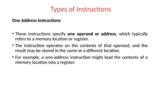
Types of Instructions
OneAddress Instructions
• These instructions specify one operand or address, which typically
refers to a memory location or register.
• The instruction operates on the contents of that operand, and the
result may be stored in the same or a different location.
• For example, a one-address instruction might load the contents of a
memory location into a register.
11.
Expression: X =(A+B)*(C+D)
AC is accumulator
M[] is any memory location
M[T] is temporary location
12.
Types of Instructions
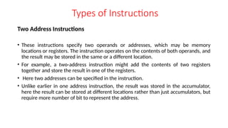
TwoAddress Instructions
• These instructions specify two operands or addresses, which may be memory
locations or registers. The instruction operates on the contents of both operands, and
the result may be stored in the same or a different location.
• For example, a two-address instruction might add the contents of two registers
together and store the result in one of the registers.
• Here two addresses can be specified in the instruction.
• Unlike earlier in one address instruction, the result was stored in the accumulator,
here the result can be stored at different locations rather than just accumulators, but
require more number of bit to represent the address.
13.
Here destination addresscan also contain an
operand.
Expression: X = (A+B)*(C+D)
R1, R2 are registers
M[] is any memory location
14.
Types of Instructions
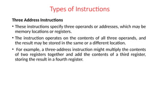
ThreeAddress Instructions
• These instructions specify three operands or addresses, which may be
memory locations or registers.
• The instruction operates on the contents of all three operands, and
the result may be stored in the same or a different location.
• For example, a three-address instruction might multiply the contents
of two registers together and add the contents of a third register,
storing the result in a fourth register.
15.
Expression: X =(A+B)*(C+D)
R1, R2 are registers
M[] is any memory location
16.
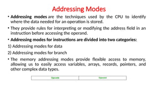
Addressing Modes
• Addressingmodes are the techniques used by the CPU to identify
where the data needed for an operation is stored.
• They provide rules for interpreting or modifying the address field in an
instruction before accessing the operand.
• Addressing modes for instructions are divided into two categories:
1) Addressing modes for data
2) Addressing modes for branch
• The memory addressing modes provide flexible access to memory,
allowing us to easily access variables, arrays, records, pointers, and
other complex data types.
17.
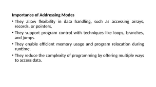
Importance of AddressingModes
• They allow flexibility in data handling, such as accessing arrays,
records, or pointers.
• They support program control with techniques like loops, branches,
and jumps.
• They enable efficient memory usage and program relocation during
runtime.
• They reduce the complexity of programming by offering multiple ways
to access data.
18.
Types of AddressingModes in Computer Architecture
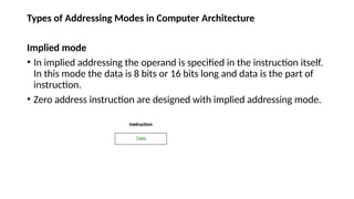
Implied mode
• In implied addressing the operand is specified in the instruction itself.
In this mode the data is 8 bits or 16 bits long and data is the part of
instruction.
• Zero address instruction are designed with implied addressing mode.
19.
Types of AddressingModes in Computer Architecture
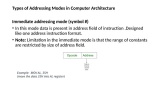
Immediate addressing mode (symbol #)
• In this mode data is present in address field of instruction .Designed
like one address instruction format.
• Note: Limitation in the immediate mode is that the range of constants
are restricted by size of address field.
Example: MOV AL, 35H
(move the data 35H into AL register)
20.
Types of AddressingModes in Computer Architecture
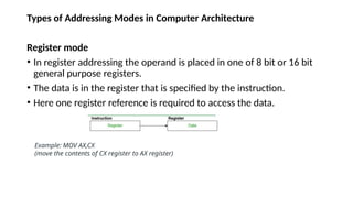
Register mode
• In register addressing the operand is placed in one of 8 bit or 16 bit
general purpose registers.
• The data is in the register that is specified by the instruction.
• Here one register reference is required to access the data.
Example: MOV AX,CX
(move the contents of CX register to AX register)
21.
Types of AddressingModes in Computer Architecture
Register Indirect mode
• In this addressing the operand’s offset is placed in any one of the
registers BX,BP,SI,DI as specified in the instruction. The effective
address of the data is in the base register or an index register that is
specified by the instruction.
• Here two register reference is required to access the data.
MOV AX, [BX]
(move the contents of memory location addressed by the register BX to the register AX)
22.
Types of AddressingModes in Computer Architecture
Auto Indexed (increment mode)
Effective address of the operand is the contents of a register specified in the
instruction.
After accessing the operand, the contents of this register are automatically
incremented to point to the next consecutive memory location.(R1)+. Here one
register reference, one memory reference and one ALU operation is required to
access the data.
Example:
Add R1, (R2)+ // OR
R1 = R1 +M[R2]
R2 = R2 + d
Useful for stepping through arrays in a loop. R2 - start of array d - size of an element
23.
Types of AddressingModes in Computer Architecture
Auto indexed ( decrement mode)
Effective address of the operand is the contents of a register specified in the
instruction. Before accessing the operand, the contents of this register are
automatically decremented to point to the previous consecutive memory location.
-(R1)Here one register reference, one memory reference and one ALU operation is
required to access the data. Example:
Add R1,-(R2) //OR
R2 = R2-d
R1 = R1 + M[R2]
Auto decrement mode is same as auto increment mode. Both can also be used to
implement a stack as push and pop . Auto increment and Auto decrement modes
are useful for implementing “Last-In-First-Out” data structures.
24.
Types of AddressingModes in Computer Architecture
Direct addressing/ Absolute addressing Mode (symbol [ ])
• The operand’s offset is given in the instruction as an 8 bit or 16 bit
displacement element.
• Here only one memory reference operation is required to access the
data.
Example: ADD AL,[0301] //add the contents of offset
address 0301 to AL
25.
Types of AddressingModes in Computer Architecture
Indirect addressing Mode (symbol @ or () )
In this mode address field of instruction contains the address of effective address.
Here two references are required. 1st reference to get effective address. 2nd reference
to access the data. Based on the availability of Effective address, Indirect mode is of
two kind:
Register Indirect: In this mode effective address is in the register, and corresponding
register name will be maintained in the address field of an instruction. Here one
register reference, one memory reference is required to access the data.
Example : MOV A, @R0
Memory Indirect: In this mode effective address is in the memory, and corresponding
memory address will be maintained in the address field of an instruction. Here two
memory reference is required to access the data.
Example : MOV AX, [[5000H]]
26.
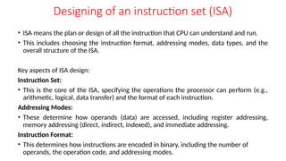
Designing of aninstruction set (ISA)
• ISA means the plan or design of all the instruction that CPU can understand and run.
• This includes choosing the instruction format, addressing modes, data types, and the
overall structure of the ISA.
Key aspects of ISA design:
Instruction Set:
• This is the core of the ISA, specifying the operations the processor can perform (e.g.,
arithmetic, logical, data transfer) and the format of each instruction.
Addressing Modes:
• These determine how operands (data) are accessed, including register addressing,
memory addressing (direct, indirect, indexed), and immediate addressing.
Instruction Format:
• This determines how instructions are encoded in binary, including the number of
operands, the operation code, and addressing modes.
27.
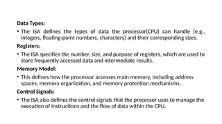
Data Types:
• TheISA defines the types of data the processor(CPU) can handle (e.g.,
integers, floating-point numbers, characters) and their corresponding sizes.
Registers:
• The ISA specifies the number, size, and purpose of registers, which are used to
store frequently accessed data and intermediate results.
Memory Model:
• This defines how the processor accesses main memory, including address
spaces, memory organization, and memory protection mechanisms.
Control Signals:
• The ISA also defines the control signals that the processor uses to manage the
execution of instructions and the flow of data within the CPU.
28.
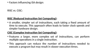
• Factors influencingISA design:
RISC vs. CISC:
RISC (Reduced Instruction Set Computing):
• A smaller, simpler set of instructions, each taking a fixed amount of
time to execute. This approach often leads to faster clock speeds and
simpler hardware design.
CISC (Complex Instruction Set Computing):
• Features a larger, more complex set of instructions, can perform
multiple operations in a single instruction.
• This approach can reduce the number of instructions needed to
execute a program but may result in slower execution times.
29.
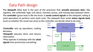
Data Path design
Thedatapath (blue box) is the part of the processor that actually processes data—like
registers, the arithmetic logic unit (ALU), memory access, and moving data between them.
The controller (green box) is like the brain: it sends control signals to the datapath, telling it
what operations to perform each clock cycle. The datapath then sends status signals back
(such as whether the result was zero) so the controller can decide what to do next;
•Controller sets up operations, making
decisions.
•Datapath executes them and returns
information.
•They operate in lockstep with the clock
signals that synchronize everything.
30.
Components Associated withData Path
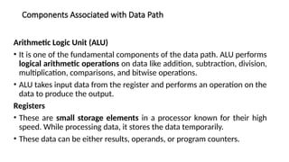
Arithmetic Logic Unit (ALU)
• It is one of the fundamental components of the data path. ALU performs
logical arithmetic operations on data like addition, subtraction, division,
multiplication, comparisons, and bitwise operations.
• ALU takes input data from the register and performs an operation on the
data to produce the output.
Registers
• These are small storage elements in a processor known for their high
speed. While processing data, it stores the data temporarily.
• These data can be either results, operands, or program counters.
31.
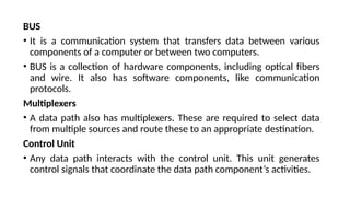
BUS
• It isa communication system that transfers data between various
components of a computer or between two computers.
• BUS is a collection of hardware components, including optical fibers
and wire. It also has software components, like communication
protocols.
Multiplexers
• A data path also has multiplexers. These are required to select data
from multiple sources and route these to an appropriate destination.
Control Unit
• Any data path interacts with the control unit. This unit generates
control signals that coordinate the data path component’s activities.
32.
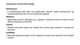
Importance of DataPath Design:
Performance:
• A well-designed data path can significantly improve system performance by
reducing execution time and increasing throughput.
Efficiency:
• Optimizing resource utilization (e.g., registers, functional units) can lead to more
efficient operation of the CPU.
Control:
• Efficient data path design can simplify the control logic needed to manage the
data flow.
Scalability:
• Data path design principles can be applied to create more powerful and scalable
systems.


![A stack-based computer does not use the address field in the instruction. To evaluate an expression, it is first converted
to reverse Polish Notation i.e. Postfix Notation.
Expression: X = (A+B)*(C+D)
Postfixed : X = AB+CD+*
TOP means top of stack
M[X] is any memory location](https://image.slidesharecdn.com/unit-1-250804083338-4683061a/85/Unit-1_Processor_Basic-Cpu_Organization-pptx-9-320.jpg)
![Expression: X = (A+B)*(C+D)
AC is accumulator
M[] is any memory location
M[T] is temporary location](https://image.slidesharecdn.com/unit-1-250804083338-4683061a/85/Unit-1_Processor_Basic-Cpu_Organization-pptx-11-320.jpg)
![Here destination address can also contain an
operand.
Expression: X = (A+B)*(C+D)
R1, R2 are registers
M[] is any memory location](https://image.slidesharecdn.com/unit-1-250804083338-4683061a/85/Unit-1_Processor_Basic-Cpu_Organization-pptx-13-320.jpg)
![Expression: X = (A+B)*(C+D)
R1, R2 are registers
M[] is any memory location](https://image.slidesharecdn.com/unit-1-250804083338-4683061a/85/Unit-1_Processor_Basic-Cpu_Organization-pptx-15-320.jpg)
![Types of Addressing Modes in Computer Architecture
Register Indirect mode
• In this addressing the operand’s offset is placed in any one of the
registers BX,BP,SI,DI as specified in the instruction. The effective
address of the data is in the base register or an index register that is
specified by the instruction.
• Here two register reference is required to access the data.
MOV AX, [BX]
(move the contents of memory location addressed by the register BX to the register AX)](https://image.slidesharecdn.com/unit-1-250804083338-4683061a/85/Unit-1_Processor_Basic-Cpu_Organization-pptx-21-320.jpg)
![Types of Addressing Modes in Computer Architecture
Auto Indexed (increment mode)
Effective address of the operand is the contents of a register specified in the
instruction.
After accessing the operand, the contents of this register are automatically
incremented to point to the next consecutive memory location.(R1)+. Here one
register reference, one memory reference and one ALU operation is required to
access the data.
Example:
Add R1, (R2)+ // OR
R1 = R1 +M[R2]
R2 = R2 + d
Useful for stepping through arrays in a loop. R2 - start of array d - size of an element](https://image.slidesharecdn.com/unit-1-250804083338-4683061a/85/Unit-1_Processor_Basic-Cpu_Organization-pptx-22-320.jpg)
![Types of Addressing Modes in Computer Architecture
Auto indexed ( decrement mode)
Effective address of the operand is the contents of a register specified in the
instruction. Before accessing the operand, the contents of this register are
automatically decremented to point to the previous consecutive memory location.
-(R1)Here one register reference, one memory reference and one ALU operation is
required to access the data. Example:
Add R1,-(R2) //OR
R2 = R2-d
R1 = R1 + M[R2]
Auto decrement mode is same as auto increment mode. Both can also be used to
implement a stack as push and pop . Auto increment and Auto decrement modes
are useful for implementing “Last-In-First-Out” data structures.](https://image.slidesharecdn.com/unit-1-250804083338-4683061a/85/Unit-1_Processor_Basic-Cpu_Organization-pptx-23-320.jpg)
![Types of Addressing Modes in Computer Architecture
Direct addressing/ Absolute addressing Mode (symbol [ ])
• The operand’s offset is given in the instruction as an 8 bit or 16 bit
displacement element.
• Here only one memory reference operation is required to access the
data.
Example: ADD AL,[0301] //add the contents of offset
address 0301 to AL](https://image.slidesharecdn.com/unit-1-250804083338-4683061a/85/Unit-1_Processor_Basic-Cpu_Organization-pptx-24-320.jpg)
![Types of Addressing Modes in Computer Architecture
Indirect addressing Mode (symbol @ or () )
In this mode address field of instruction contains the address of effective address.
Here two references are required. 1st reference to get effective address. 2nd reference
to access the data. Based on the availability of Effective address, Indirect mode is of
two kind:
Register Indirect: In this mode effective address is in the register, and corresponding
register name will be maintained in the address field of an instruction. Here one
register reference, one memory reference is required to access the data.
Example : MOV A, @R0
Memory Indirect: In this mode effective address is in the memory, and corresponding
memory address will be maintained in the address field of an instruction. Here two
memory reference is required to access the data.
Example : MOV AX, [[5000H]]](https://image.slidesharecdn.com/unit-1-250804083338-4683061a/85/Unit-1_Processor_Basic-Cpu_Organization-pptx-25-320.jpg)