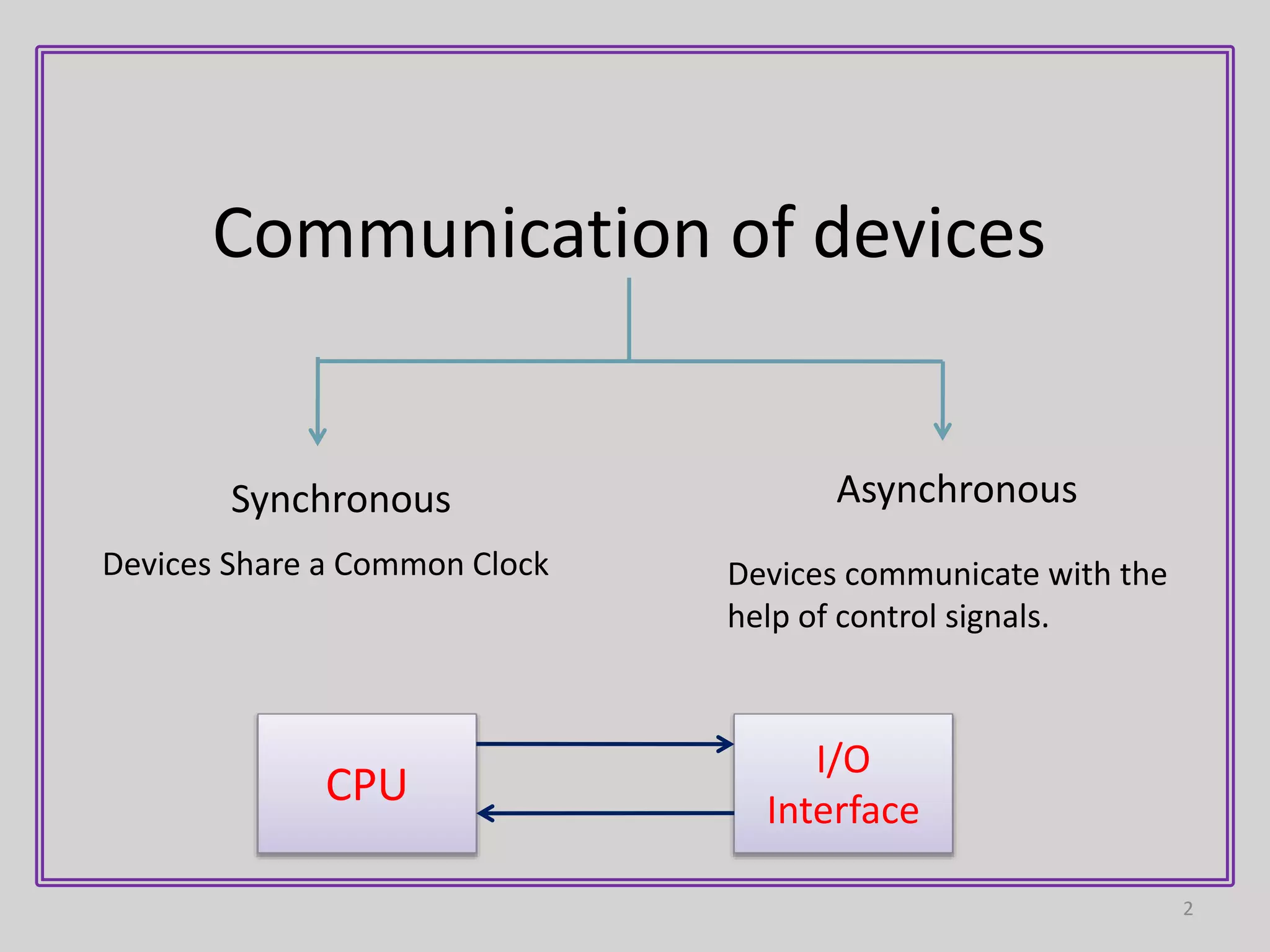
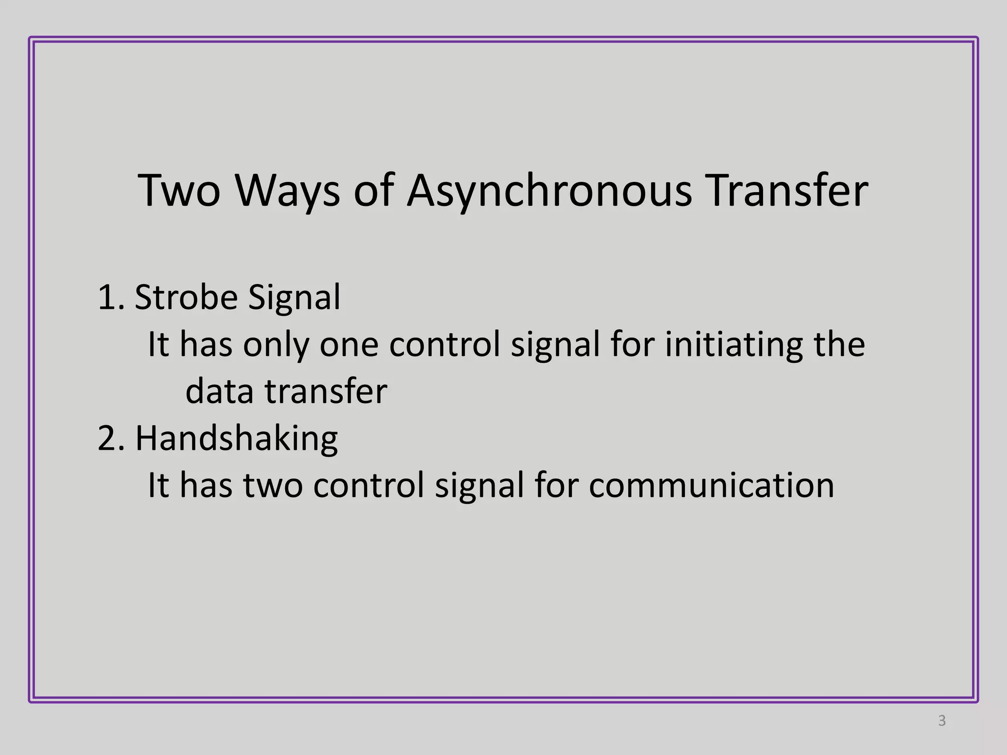
1) Asynchronous data transfer uses control signals rather than a shared clock to communicate between devices. There are two methods: strobe signals with one control line, and handshaking with two control lines.
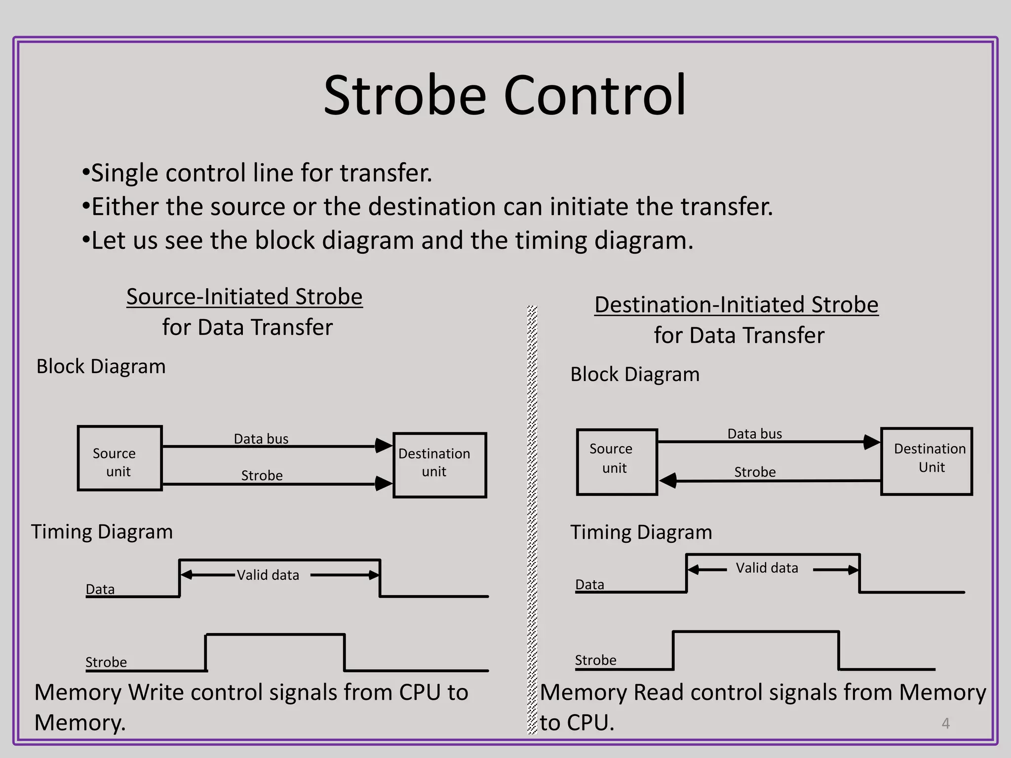
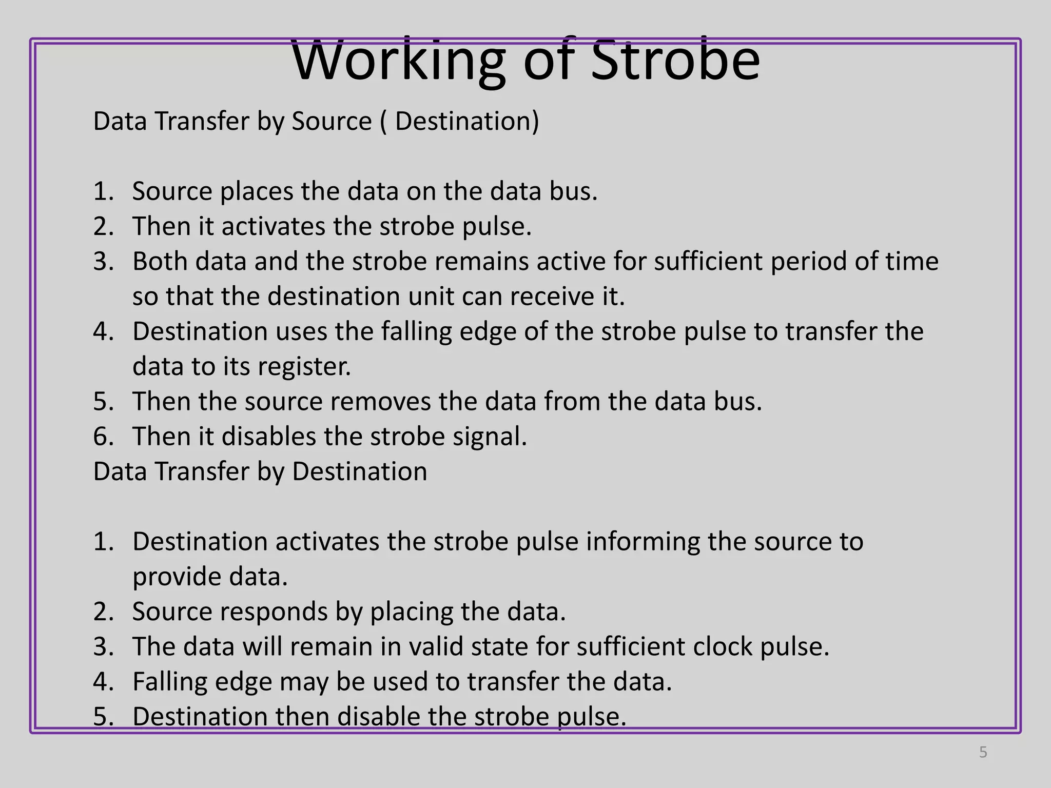
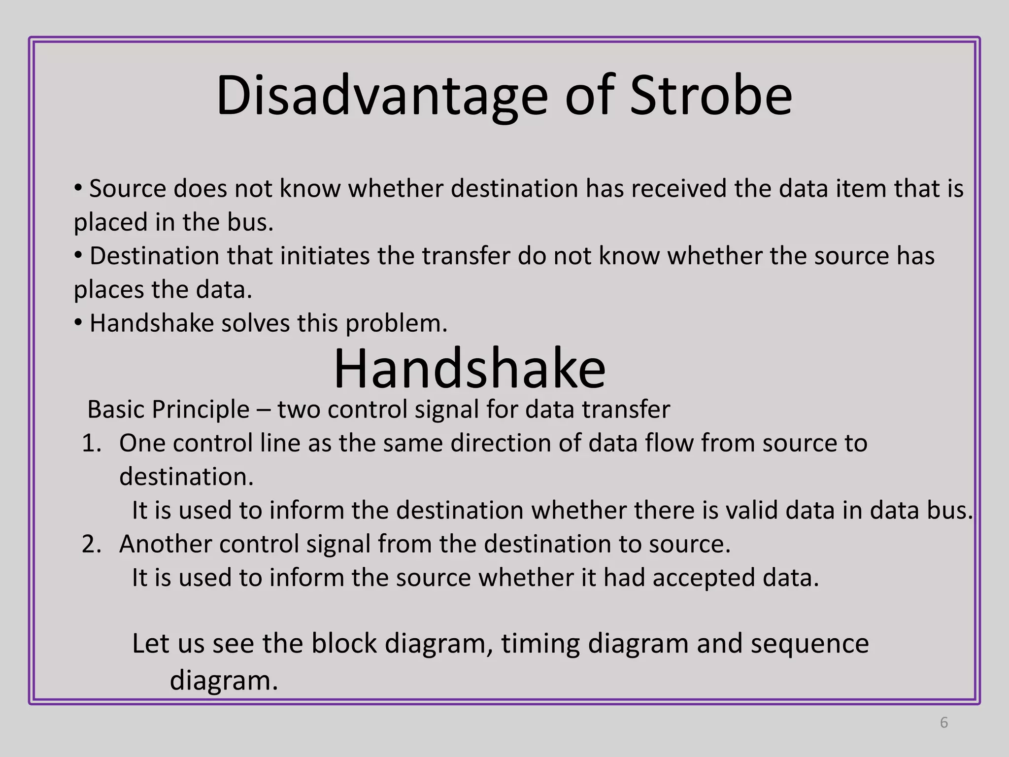
2) In strobe signaling, either the source or destination can initiate data transfer by activating a strobe pulse along with data on the data bus. There is no confirmation that the data was received.
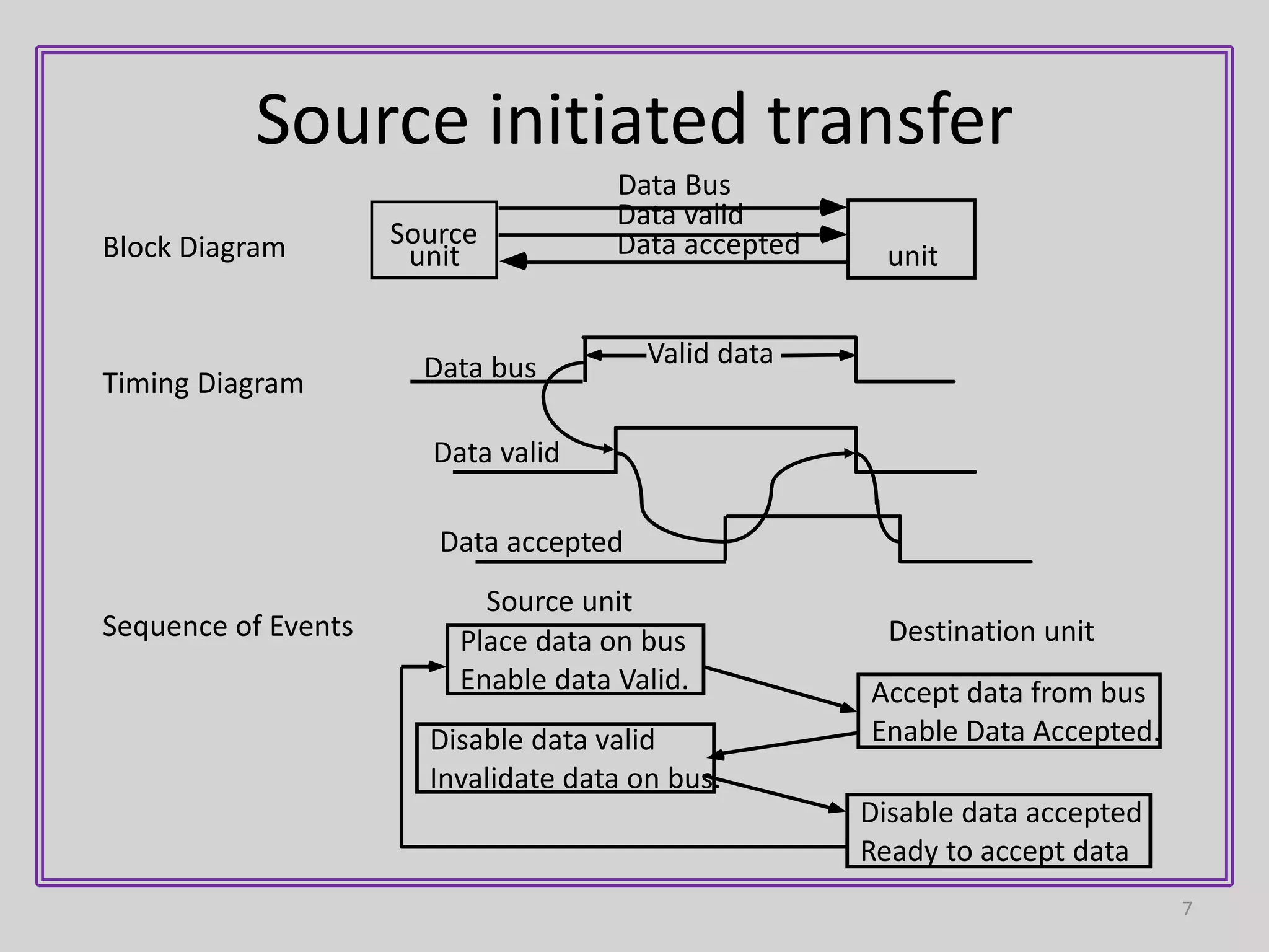
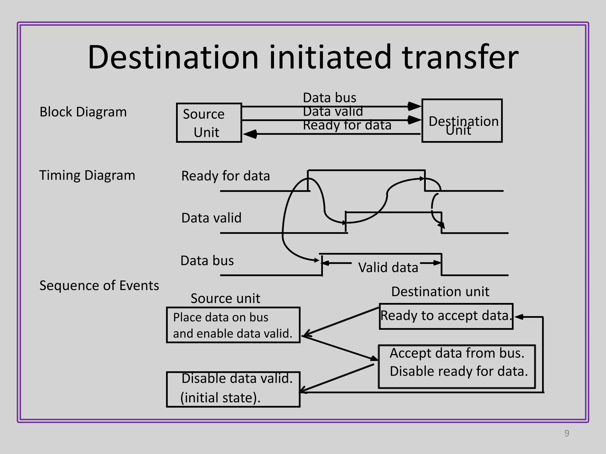
3) Handshaking uses two control lines - one for data validity from source to destination, and another for data acceptance from destination to source. This allows each device to operate independently while confirming the data transfer was completed.