Downloaded 102 times
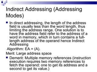
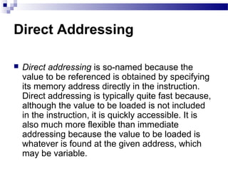
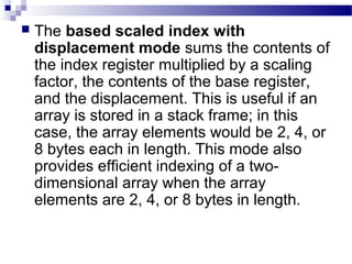
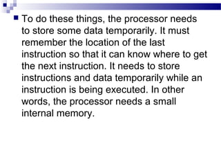
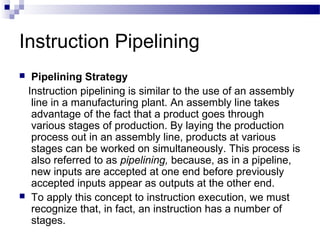
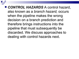
![ LOAD/STORE ADDRESSING Load and store
instructions are the only instructions that reference
memory. This is always done indirectly through a base
register plus offset. There are three alternatives with
respect to indexing:
Offset: For this addressing method, indexing is not
used. An offset value is added to or subtracted from the
value in the base register to form the memory address.
As an example Figure 11.3a illustrates this method with
the assembly language instruction STRB r0, [r1, #12].
This is the store byte instruction. In this case the base
address is in register r1 and the displacement is an
immediate value of decimal 12. The resulting address
(base plus offset) is the location where the least
significant byte from r0 is to be stored](https://image.slidesharecdn.com/advancedcomputerarchitectlesson3and4-140421050708-phpapp01/85/Advanced-computer-architect-lesson-3-and-4-28-320.jpg)
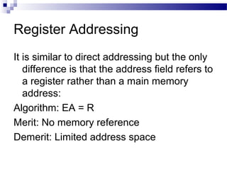
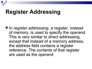
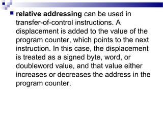
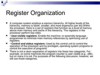
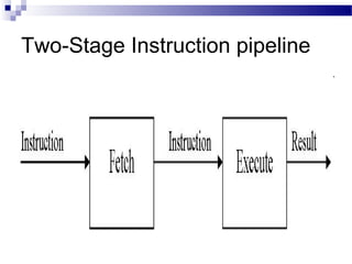
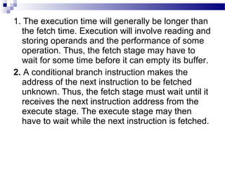
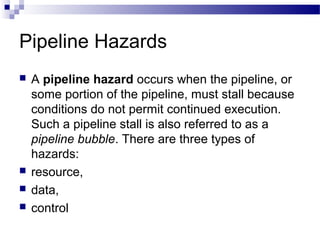
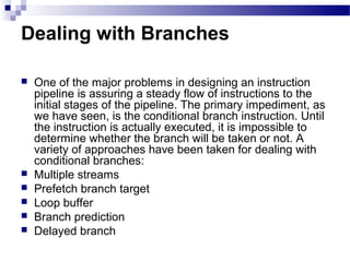
![ Preindex: The memory address is formed in the
same way as for offset addressing. The memory
address is also written back to the base register.
In other words, the base register value is
incremented or decremented by the offset value.
Figure below illustrates this method with the
assembly language instruction STRB r0, [r1,
#12]!. The exclamation point signifies
preindexing.
Postindex:The memory address is the base
register value.An offset is added to or subtracted
from the base register value and the result is
written back to the base register. Figure below
illustrates this method with the assembly
language instruction STRB r0, [r1], #12.](https://image.slidesharecdn.com/advancedcomputerarchitectlesson3and4-140421050708-phpapp01/85/Advanced-computer-architect-lesson-3-and-4-29-320.jpg)
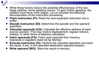
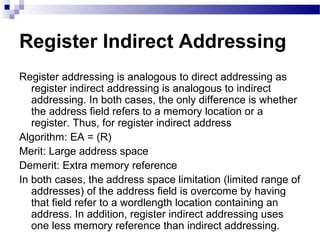
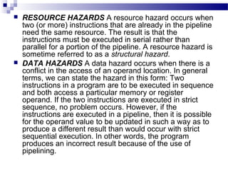
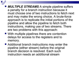
![ Some of the IBM S/360 designers pointed out two factors that
frustrate this seemingly simple pattern for high performance design
[ANDE67a], and they remain elements that designer must still
consider:
1. At each stage of the pipeline, there is some overhead involved in
moving data from buffer to buffer and in performing various
preparation and delivery functions. This overhead can appreciably
lengthen the total execution time of a single instruction. This is
significant when sequential instructions are logically dependent,
either through heavy use of branching or through memory access
dependencies.
2. The amount of control logic required to handle memory and register
dependencies and to optimize the use of the pipeline increases
enormously with the number of stages. This can lead to a situation
where the logic controlling the gating between stages is more
complex than the stages being controlled.
Another consideration is latching delay: It takes time for pipeline buffers
to operate and this adds to instruction cycle time. Instruction
pipelining is a powerful technique for enhancing performance but
requires careful design to achieve optimum results with reasonable
complexity](https://image.slidesharecdn.com/advancedcomputerarchitectlesson3and4-140421050708-phpapp01/85/Advanced-computer-architect-lesson-3-and-4-65-320.jpg)
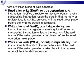
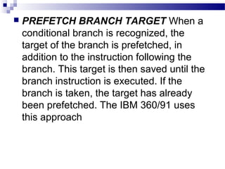
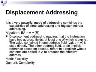
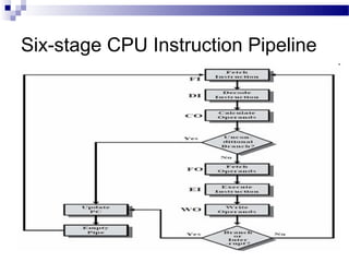
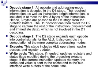
![Intel 80486 Pipelining
An instructive example of an instruction pipeline is that of
the Intel 80486. The 80486 implements a five-stage
pipeline:
Fetch: Instructions are fetched from the cache or from
external memory and placed into one of the two 16-byte
prefetch buffers.The objective of the fetch stage is to fill
the prefetch buffers with new data as soon as the old
data have been consumed by the instruction decoder.
Because instructions are of variable length (from 1 to 11
bytes not counting prefixes), the status of the prefetcher
relative to the other pipeline stages varies from
instruction to instruction. On average, about five
instructions are fetched with each 16-byte load
[CRAW90].The fetch stage operates independently of
the other stages to keep the prefetch buffers full](https://image.slidesharecdn.com/advancedcomputerarchitectlesson3and4-140421050708-phpapp01/85/Advanced-computer-architect-lesson-3-and-4-76-320.jpg)

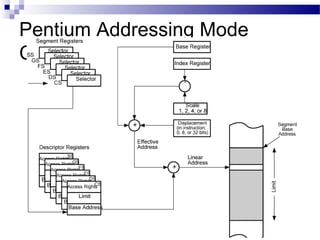
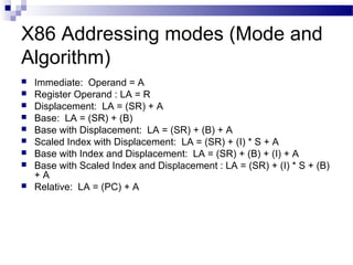
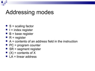
The document discusses various addressing modes used in instruction sets including immediate, direct, indirect, register, register indirect, displacement, indexed, stack, and relative addressing. It provides the algorithms and merits and demerits of each mode. For example, immediate addressing has the operand value in the instruction but is limited in magnitude, while indirect addressing allows a large address space but requires multiple memory references. The document also summarizes addressing modes for various processors like Pentium, x86, PowerPC and their calculations.