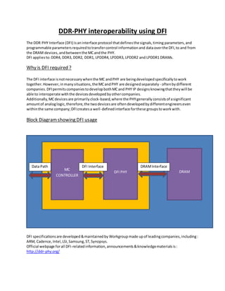
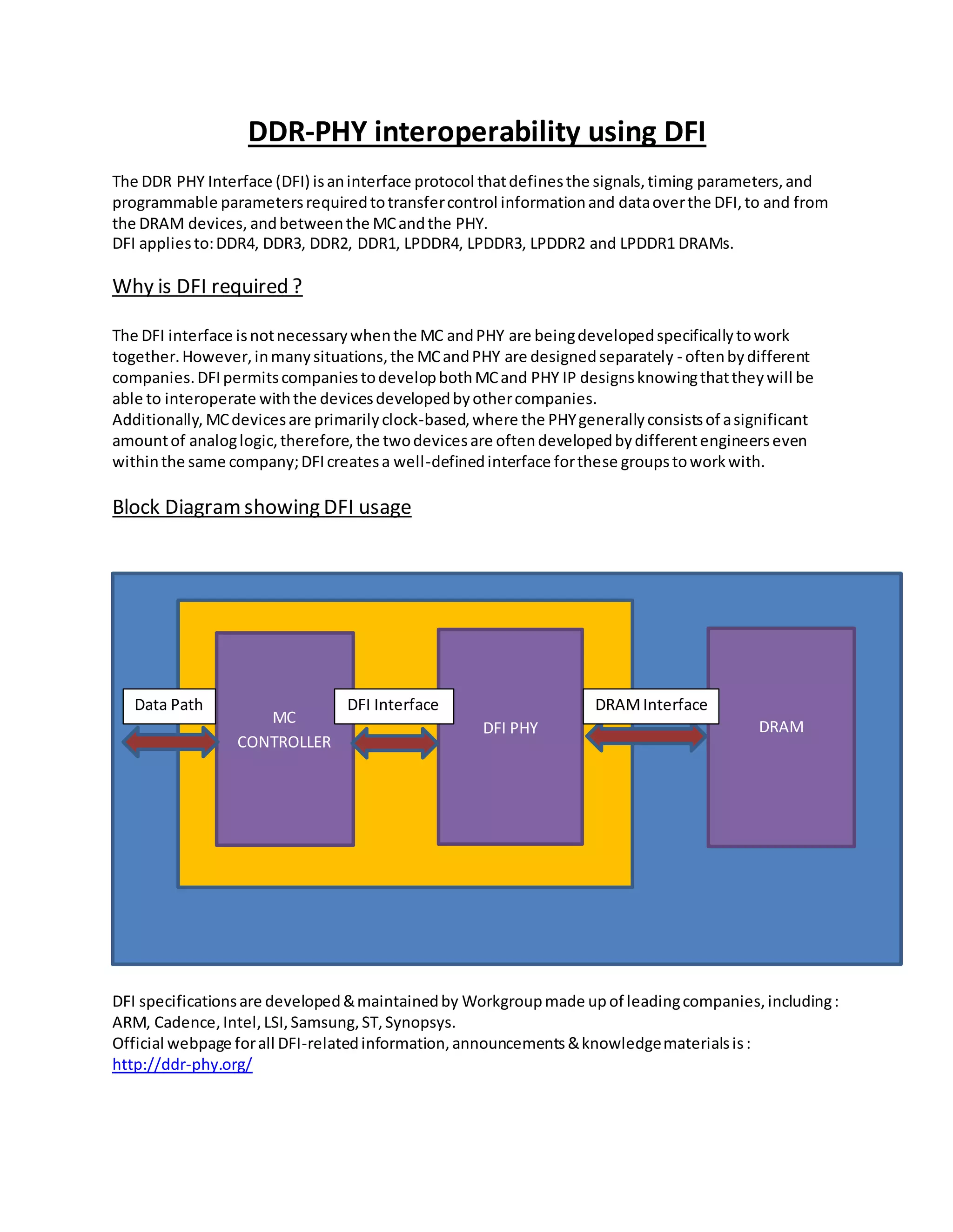
DDR-PHY interoperability using DFI
The DDR PHY Interface (DFI) isaninterface protocol thatdefinesthe signals,timing parameters,and
programmable parametersrequiredtotransfercontrol informationand dataoverthe DFI,to and from
the DRAM devices, andbetweenthe MCandthe PHY.
DFI appliesto:DDR4, DDR3, DDR2, DDR1, LPDDR4, LPDDR3, LPDDR2 and LPDDR1 DRAMs.
Why is DFI required ?
The DFI interface isnotnecessarywhenthe MC andPHY are beingdevelopedspecificallytowork
together.However,inmanysituations,the MCandPHY are designedseparately - oftenbydifferent
companies.DFIpermitscompaniestodevelopbothMCand PHY IP designsknowingthattheywill be
able to interoperate withthe devicesdevelopedbyothercompanies.
Additionally, MCdevicesare primarilyclock-based,where the PHYgenerallyconsistsof asignificant
amountof analoglogic,therefore,the twodevicesare oftendevelopedbydifferentengineerseven
withinthe same company;DFIcreatesa well-definedinterface forthese groupstoworkwith.
Block Diagramshowing DFI usage
DFI specificationsare developed&maintainedby Workgroupmade up of leadingcompanies,including:
ARM, Cadence,Intel,LSI,Samsung,ST,Synopsys.
Official webpage forall DFI-relatedinformation,announcements&knowledgematerialsis:
http://ddr-phy.org/
Data Path
DRAMDFI PHY
MC
CONTROLLER
DFI InterfaceData Path DRAMInterface
Frequency Ratios Across theDFI
In a DDR memorysubsystem,itmaybe advantageoustooperate the PHYat a higher frequencythanthe
MC. If the PHY operatesat a multiple of the MCfrequency,the PHY transfersdataat a higherdatarate
relative tothe DFIclock and the MC hasthe optionto execute multiplecommandsinasingle DFIclock
cycle.
The DFI specificationsupportsa 1:1, 1:2 or 1:4 MC to PHY frequencyratio,definingthe relationshipof
the reference clocksforthe MC and the PHY.
Frequencyratioallowsthe DRAMto run at higherfrequencieswithamemorycontroller(andSOC) that
run at a lowerfrequency. Runningmemoryata higherfrequencycertainlyhasthe potential forhigher
performance.Butthe actual performance of the systemwill dependonmanyfactors. The utilization
whenusingfrequencyratiomaybe lowerdependingonhow optimallythe MCcan schedule commands
inthismode of operation.Butevenif the utilizationisnotasoptimized,the 2X(or 4X) memoryclock
frequencymaystill be asignificantperformance increase.
ComparativeStudy of Frequency Ratios
The followingtable showsacomparisonof “CPU time”consumedbya reference testcasefromDFIVIP
on VCS:
Frequency Ratio CPU time
1:1 2.040 seconds
1:2 1.950 seconds
1:4 1.840 seconds
The above table showsimprovementsinCPUtime aswe move towards1:4 ratio from1:1 ratio.This isa
bigimprovementwithasingle testcase,imagine whenhuge numberof testcasesare run,andwithan
actual DUT design!
The DFI specificationdefinesa frequencychange protocol betweenthe MCandthe PHY to allow the
devicestochange the clockfrequencyof the memorycontrollerand PHYwithoutcompletelyre-setting
the system.
Salient Features of DFI Protocol
 No restrictionsonMC or PHY - The DFI protocol doesnotencompassall of the featuresof the
MC or the PHY, nor doesthe protocol putany restrictionsonhow the MC or the PHY interface
to otheraspectsof the system.
 Data Bus Inversion - DBIcan be usedforreducingthe numberof transitionson the busand/or
reducingthe noise andpowerconsumptiononthe bus.
 DFI readand write trainingoperationscanincrease accuracyof signal placementat higher
speedsinDDR4, DDR3, LPDDR4, LPDDR3 and LPDDR2 systems.
 Low PowerMode - If the PHY hasknowledge thatthe DFIwill be idle foraperiodof time,the
PHY may be able to entera MC-initiatedlow powerstate.
DFI ProtocolEvolution
The latestDFI specsversionisVersion4.0,Revision2.The specshas undergone several major
enhancementsoverthe yearsandfollowingisbrief history:
Version Feature Updates
1.0 Initial Release
2.0 DDR3 support
2.1 LPDDR2 support
3.0 DDR4 support
3.1 LPDDR3 support
4.0 R2 LPDDR4 support (Latest)
Stay tunedformore…

DFI_Blog

  • 1.
    DDR-PHY interoperability usingDFI The DDR PHY Interface (DFI) isaninterface protocol thatdefinesthe signals,timing parameters,and programmable parametersrequiredtotransfercontrol informationand dataoverthe DFI,to and from the DRAM devices, andbetweenthe MCandthe PHY. DFI appliesto:DDR4, DDR3, DDR2, DDR1, LPDDR4, LPDDR3, LPDDR2 and LPDDR1 DRAMs. Why is DFI required ? The DFI interface isnotnecessarywhenthe MC andPHY are beingdevelopedspecificallytowork together.However,inmanysituations,the MCandPHY are designedseparately - oftenbydifferent companies.DFIpermitscompaniestodevelopbothMCand PHY IP designsknowingthattheywill be able to interoperate withthe devicesdevelopedbyothercompanies. Additionally, MCdevicesare primarilyclock-based,where the PHYgenerallyconsistsof asignificant amountof analoglogic,therefore,the twodevicesare oftendevelopedbydifferentengineerseven withinthe same company;DFIcreatesa well-definedinterface forthese groupstoworkwith. Block Diagramshowing DFI usage DFI specificationsare developed&maintainedby Workgroupmade up of leadingcompanies,including: ARM, Cadence,Intel,LSI,Samsung,ST,Synopsys. Official webpage forall DFI-relatedinformation,announcements&knowledgematerialsis: http://ddr-phy.org/ Data Path DRAMDFI PHY MC CONTROLLER DFI InterfaceData Path DRAMInterface
  • 2.
    Frequency Ratios AcrosstheDFI In a DDR memorysubsystem,itmaybe advantageoustooperate the PHYat a higher frequencythanthe MC. If the PHY operatesat a multiple of the MCfrequency,the PHY transfersdataat a higherdatarate relative tothe DFIclock and the MC hasthe optionto execute multiplecommandsinasingle DFIclock cycle. The DFI specificationsupportsa 1:1, 1:2 or 1:4 MC to PHY frequencyratio,definingthe relationshipof the reference clocksforthe MC and the PHY. Frequencyratioallowsthe DRAMto run at higherfrequencieswithamemorycontroller(andSOC) that run at a lowerfrequency. Runningmemoryata higherfrequencycertainlyhasthe potential forhigher performance.Butthe actual performance of the systemwill dependonmanyfactors. The utilization whenusingfrequencyratiomaybe lowerdependingonhow optimallythe MCcan schedule commands inthismode of operation.Butevenif the utilizationisnotasoptimized,the 2X(or 4X) memoryclock frequencymaystill be asignificantperformance increase. ComparativeStudy of Frequency Ratios The followingtable showsacomparisonof “CPU time”consumedbya reference testcasefromDFIVIP on VCS: Frequency Ratio CPU time 1:1 2.040 seconds 1:2 1.950 seconds 1:4 1.840 seconds
  • 3.
    The above tableshowsimprovementsinCPUtime aswe move towards1:4 ratio from1:1 ratio.This isa bigimprovementwithasingle testcase,imagine whenhuge numberof testcasesare run,andwithan actual DUT design! The DFI specificationdefinesa frequencychange protocol betweenthe MCandthe PHY to allow the devicestochange the clockfrequencyof the memorycontrollerand PHYwithoutcompletelyre-setting the system. Salient Features of DFI Protocol  No restrictionsonMC or PHY - The DFI protocol doesnotencompassall of the featuresof the MC or the PHY, nor doesthe protocol putany restrictionsonhow the MC or the PHY interface to otheraspectsof the system.  Data Bus Inversion - DBIcan be usedforreducingthe numberof transitionson the busand/or reducingthe noise andpowerconsumptiononthe bus.  DFI readand write trainingoperationscanincrease accuracyof signal placementat higher speedsinDDR4, DDR3, LPDDR4, LPDDR3 and LPDDR2 systems.  Low PowerMode - If the PHY hasknowledge thatthe DFIwill be idle foraperiodof time,the PHY may be able to entera MC-initiatedlow powerstate. DFI ProtocolEvolution The latestDFI specsversionisVersion4.0,Revision2.The specshas undergone several major enhancementsoverthe yearsandfollowingisbrief history: Version Feature Updates 1.0 Initial Release 2.0 DDR3 support 2.1 LPDDR2 support 3.0 DDR4 support 3.1 LPDDR3 support 4.0 R2 LPDDR4 support (Latest) Stay tunedformore…