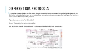
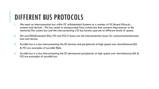
The document discusses various bus protocols, including the ISA, EISA, PCI, and AMBA, that facilitate communication between processors and I/O devices in computer and embedded systems. It details the specifications, advantages, and limitations of each protocol, emphasizing the need for high-speed data transfer and efficiency in system designs. Additionally, it describes the features and benefits of the AMBA architecture for complex system-on-chip designs, highlighting its role in improving compatibility, reusability, and performance.
![ISA AND EISA BUSES
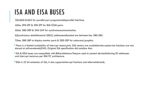
An ISA bus connects only to embedded deviceswhich has an 8086,80186,80286 processor.
The limitations for memory access by system usingISA bus of original IBM PC are as follows:
ISA bus memory can be of two ranges 640Kbto 1Mb & 15Mb to 16Mb.The former rangeoverlays with the range
used by video boardsand BIOS.LinuxOS doesnotsupport thesecond range directly for accessing a device.
The limitations of IO port addresses for deviceare as follows:
8086 & 80286 processor has IO mapped I/O’s notmemory mapped I/O’s.
Instruction set provides IO instruction for 64kb IOaddresses ,the IBM PC configuration ignores theaddress lines A10 to
A15 and they are notdecoded, ie. Only 1024 IO port addresses areavailable [in hexadecimal nipple representation
itranges from 00F]
Following are the addresses allocated in IBM
standard architecture(ISA)
1)Addresses from 0x000-ox00F for DMA chip.
2)0x020 -0x021 addresses allocated for PIC 82C55.](https://image.slidesharecdn.com/busprotocolandambatransactions-241108070031-64c6753a/85/BUS-PROTOCOL-AND-AMBA-_TRANSACTIONS-pptx-4-320.jpg)