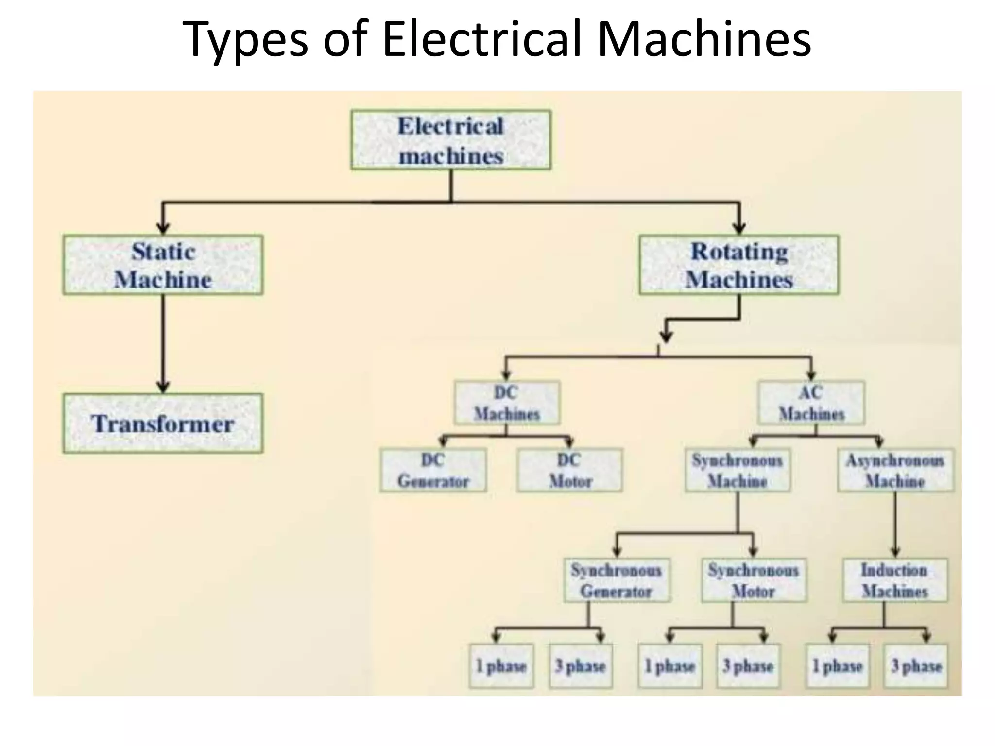
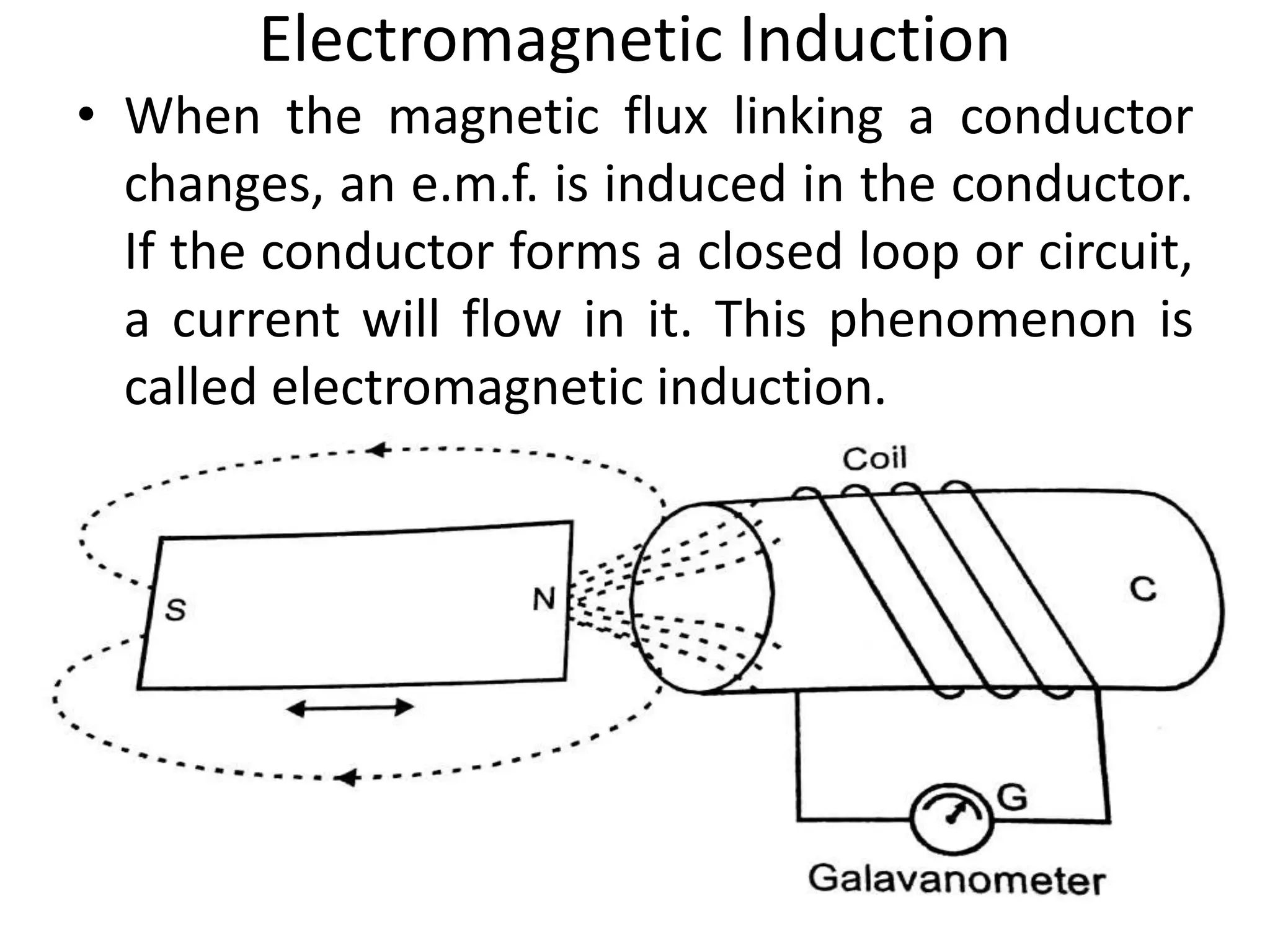
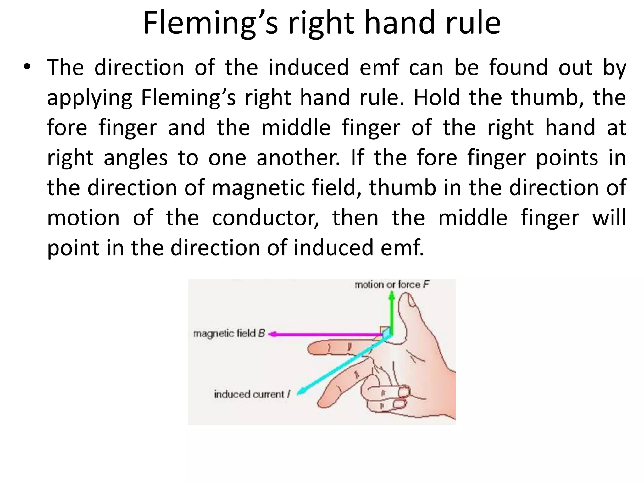
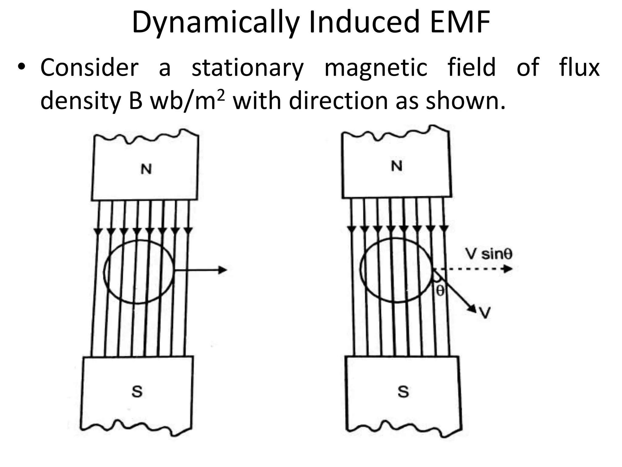
A synchronous motor is electrically identical with an alternator or AC generator.
A given alternator ( or synchronous machine) can be used as a motor, when driven electrically.
Some characteristic features of a synchronous motor are as follows:
1. It runs either at synchronous speed or not at all i.e. while running it maintains a constant speed. The only way to change its speed is to vary the supply frequency (because NS=120f/P).
2. It is not inherently self-starting. It has to be run up to synchronous (or near synchronous) speed by some means, before it can be synchronized to the supply.
3. It is capable of being operated under a wide range of power factors, both lagging and leading. Hence, it can be used for power correction purposes, in addition to supplying torque to drive loads.
Power measurement is a valid technique to measure that how much the power is being transmitted through the entire system.
In this presentation you will estimate and understand the following objectives
Wattmeter as a device
Power measurement techniques
Classical based history
Construction of wattmeter
Working of Wattmeter
Power measurement of direct and indirect way
Power measurement in three phase applications
Applications of Wattmeter
A Project made for my School in the 10th Grade explaining the differences and working of AC and DC Generators.
Contents:
-Introduction
-Electromagnetic induction
-EMF- Electromotive Force
-Fleming’s Right Hand Rule
-Components of a Generator
*Rotor
*Armature
*Coil
*Stator
*Field electromagnets
*Brushes
-A.C. generators
-Commercial A.C generators
-DC generators
-Principle
-Working
-Differences between AC and DC
Alternating current (AC), is an electric current in which the flow of electric charge periodically reverses direction, whereas in direct current (DC, also dc), the flow of electric charge is only in one direction.
Breaking,Types of Electrical Braking system, Regenerative Braking, Plugging ...Waqas Afzal
Why Breaking?
Requirements for Braking
Types of Electrical Braking system
Regenerative Braking.
Plugging type braking.
Dynamic braking.
Breaking implementations at DC Motor and AC Motor
SINGLE PHASE INDUCTION MOTORS AND SPECIAL MACHINESRagulS61
Constructional details – Double revolving field theory – Equivalent circuit – Starting methods – Role of induction motor in industries and household appliances – Reluctance motor - Servo motor - Stepper motor - Universal motor - Switched reluctance motor - Linear induction motor – Linear Synchronous motor.
This presentation contains basics of Magnetic circuits such as, magnetic flux, flux density, MMF, Reluctance, Magnetization Curve(B-H Curve), Difference between Electric & Magnetic Circuit, Series & Parallel magnetic Circuits etc.
Lecture Outline
Introduction to subject
Application Areas
Power Electronic Devices
Power Converters
What is power electronics?
1) Definition
Power Electronics: is the electronics applied to conversion and control of electric power.
Prerequisites
Power electronics incorporates concepts from the fields of
Analog circuits
Electronic devices
Control systems
Power systems
Magnetics
Electric machines
Numerical simulation
Scope
It is not possible to build practical computers, cell phones, personal data devices, cars, airplanes, industrial processes, and other everyday products without power electronics.
Alternative energy systems such as wind generators, solar power, fuel cells, and others require power electronics to function.
Technology advances such as electric and hybrid vehicles, laptop computers, microwave ovens, flat-panel displays, LED lighting, and hundreds of other innovations were not possible until advances in power electronics enabled their implementation.
Although no one can predict the future, it is certain that power electronics will be at the heart of fundamental energy innovations.
Applications: Electric VehicleTesla Model S
Functions of the power electronics:
1. Convert the DC battery voltage to the variable AC required to drive the AC motor
240 V battery
Variable-frequency, variable-voltage AC drives the motor
AC motor propels the rear axle
Up to 330 kW (acceleration)
Up to 60 kW regenerative braking
2. Control charging of the battery
Interface to 240 V 60 Hz 1φ 100 A circuit in garage.
Control AC current waveform to be sinusoidal, unity power factor.
Control charging of battery to maximize life.
Applications: Hybrid VehiclesPrius
Power Electronics Module:
Convert the DC battery voltage to the variable AC required to drive the AC motor.
Includes dc-dc boost converter and dc-3φ ac inverter
Control system can operate in all-electric mode or in hybrid gas+electric mode
Partial-power electronics
Output equation of Induction motor; Main dimensions; Separation of D and L; Choice of Average flux density; length of air gap; Design of Stator core; Rules for selecting rotor slots of squirrel cage machines; Design of rotor bars and slots; Design of end rings; Design of wound rotor; Magnetic leakage calculations; Leakage reactance of polyphase machines; Magnetizing current; Short circuit current; Operating characteristics; Losses and Efficiency.
A detailed presentation explaining the principles of electromagnetism. It covers the fundamental laws given by Faraday regarding electromagnetic induction.
ELECTROMAGNETISM
INTRODUCTION
The phenomenon where by electricity creates magnetism is known as electromagnetism. When an insulated wire is wrapped with round an iron nail and the ends of the wire connected to the battery the nail becomes capable of picking up iron fillings paper. This is a simple electromagnet. The nail has been magnetized by the current in the wire. Disconnecting the wire from the battery the paper clips fall off. The nail looses most of first magnetism when the current is switched off. The passage of electric current along a wire creates a magnetic field around the wire. The lines of forces due to a straight current carrying wire are circles, center on the wire on the wire. The field is strongest near the wire the direction of the magnetic field is r
Magnetic Effects of Electric Current for Grade 10th StudentsMurari Parashar
In this chapter, we will study the effects of electric current : Moving charges or electric current generates a magnetic field. This is useful to CBSE Students.
Saudi Arabia stands as a titan in the global energy landscape, renowned for its abundant oil and gas resources. It's the largest exporter of petroleum and holds some of the world's most significant reserves. Let's delve into the top 10 oil and gas projects shaping Saudi Arabia's energy future in 2024.
Cosmetic shop management system project report.pdfKamal Acharya
Buying new cosmetic products is difficult. It can even be scary for those who have sensitive skin and are prone to skin trouble. The information needed to alleviate this problem is on the back of each product, but it's thought to interpret those ingredient lists unless you have a background in chemistry.
Instead of buying and hoping for the best, we can use data science to help us predict which products may be good fits for us. It includes various function programs to do the above mentioned tasks.
Data file handling has been effectively used in the program.
The automated cosmetic shop management system should deal with the automation of general workflow and administration process of the shop. The main processes of the system focus on customer's request where the system is able to search the most appropriate products and deliver it to the customers. It should help the employees to quickly identify the list of cosmetic product that have reached the minimum quantity and also keep a track of expired date for each cosmetic product. It should help the employees to find the rack number in which the product is placed.It is also Faster and more efficient way.
Student information management system project report ii.pdfKamal Acharya
Our project explains about the student management. This project mainly explains the various actions related to student details. This project shows some ease in adding, editing and deleting the student details. It also provides a less time consuming process for viewing, adding, editing and deleting the marks of the students.
NO1 Uk best vashikaran specialist in delhi vashikaran baba near me online vas...Amil Baba Dawood bangali
Contact with Dawood Bhai Just call on +92322-6382012 and we'll help you. We'll solve all your problems within 12 to 24 hours and with 101% guarantee and with astrology systematic. If you want to take any personal or professional advice then also you can call us on +92322-6382012 , ONLINE LOVE PROBLEM & Other all types of Daily Life Problem's.Then CALL or WHATSAPP us on +92322-6382012 and Get all these problems solutions here by Amil Baba DAWOOD BANGALI
#vashikaranspecialist #astrologer #palmistry #amliyaat #taweez #manpasandshadi #horoscope #spiritual #lovelife #lovespell #marriagespell#aamilbabainpakistan #amilbabainkarachi #powerfullblackmagicspell #kalajadumantarspecialist #realamilbaba #AmilbabainPakistan #astrologerincanada #astrologerindubai #lovespellsmaster #kalajaduspecialist #lovespellsthatwork #aamilbabainlahore#blackmagicformarriage #aamilbaba #kalajadu #kalailam #taweez #wazifaexpert #jadumantar #vashikaranspecialist #astrologer #palmistry #amliyaat #taweez #manpasandshadi #horoscope #spiritual #lovelife #lovespell #marriagespell#aamilbabainpakistan #amilbabainkarachi #powerfullblackmagicspell #kalajadumantarspecialist #realamilbaba #AmilbabainPakistan #astrologerincanada #astrologerindubai #lovespellsmaster #kalajaduspecialist #lovespellsthatwork #aamilbabainlahore #blackmagicforlove #blackmagicformarriage #aamilbaba #kalajadu #kalailam #taweez #wazifaexpert #jadumantar #vashikaranspecialist #astrologer #palmistry #amliyaat #taweez #manpasandshadi #horoscope #spiritual #lovelife #lovespell #marriagespell#aamilbabainpakistan #amilbabainkarachi #powerfullblackmagicspell #kalajadumantarspecialist #realamilbaba #AmilbabainPakistan #astrologerincanada #astrologerindubai #lovespellsmaster #kalajaduspecialist #lovespellsthatwork #aamilbabainlahore #Amilbabainuk #amilbabainspain #amilbabaindubai #Amilbabainnorway #amilbabainkrachi #amilbabainlahore #amilbabaingujranwalan #amilbabainislamabad
Overview of the fundamental roles in Hydropower generation and the components involved in wider Electrical Engineering.
This paper presents the design and construction of hydroelectric dams from the hydrologist’s survey of the valley before construction, all aspects and involved disciplines, fluid dynamics, structural engineering, generation and mains frequency regulation to the very transmission of power through the network in the United Kingdom.
Author: Robbie Edward Sayers
Collaborators and co editors: Charlie Sims and Connor Healey.
(C) 2024 Robbie E. Sayers
Hybrid optimization of pumped hydro system and solar- Engr. Abdul-Azeez.pdffxintegritypublishin
Advancements in technology unveil a myriad of electrical and electronic breakthroughs geared towards efficiently harnessing limited resources to meet human energy demands. The optimization of hybrid solar PV panels and pumped hydro energy supply systems plays a pivotal role in utilizing natural resources effectively. This initiative not only benefits humanity but also fosters environmental sustainability. The study investigated the design optimization of these hybrid systems, focusing on understanding solar radiation patterns, identifying geographical influences on solar radiation, formulating a mathematical model for system optimization, and determining the optimal configuration of PV panels and pumped hydro storage. Through a comparative analysis approach and eight weeks of data collection, the study addressed key research questions related to solar radiation patterns and optimal system design. The findings highlighted regions with heightened solar radiation levels, showcasing substantial potential for power generation and emphasizing the system's efficiency. Optimizing system design significantly boosted power generation, promoted renewable energy utilization, and enhanced energy storage capacity. The study underscored the benefits of optimizing hybrid solar PV panels and pumped hydro energy supply systems for sustainable energy usage. Optimizing the design of solar PV panels and pumped hydro energy supply systems as examined across diverse climatic conditions in a developing country, not only enhances power generation but also improves the integration of renewable energy sources and boosts energy storage capacities, particularly beneficial for less economically prosperous regions. Additionally, the study provides valuable insights for advancing energy research in economically viable areas. Recommendations included conducting site-specific assessments, utilizing advanced modeling tools, implementing regular maintenance protocols, and enhancing communication among system components.
CFD Simulation of By-pass Flow in a HRSG module by R&R Consult.pptxR&R Consult
CFD analysis is incredibly effective at solving mysteries and improving the performance of complex systems!
Here's a great example: At a large natural gas-fired power plant, where they use waste heat to generate steam and energy, they were puzzled that their boiler wasn't producing as much steam as expected.
R&R and Tetra Engineering Group Inc. were asked to solve the issue with reduced steam production.
An inspection had shown that a significant amount of hot flue gas was bypassing the boiler tubes, where the heat was supposed to be transferred.
R&R Consult conducted a CFD analysis, which revealed that 6.3% of the flue gas was bypassing the boiler tubes without transferring heat. The analysis also showed that the flue gas was instead being directed along the sides of the boiler and between the modules that were supposed to capture the heat. This was the cause of the reduced performance.
Based on our results, Tetra Engineering installed covering plates to reduce the bypass flow. This improved the boiler's performance and increased electricity production.
It is always satisfying when we can help solve complex challenges like this. Do your systems also need a check-up or optimization? Give us a call!
Work done in cooperation with James Malloy and David Moelling from Tetra Engineering.
More examples of our work https://www.r-r-consult.dk/en/cases-en/
Explore the innovative world of trenchless pipe repair with our comprehensive guide, "The Benefits and Techniques of Trenchless Pipe Repair." This document delves into the modern methods of repairing underground pipes without the need for extensive excavation, highlighting the numerous advantages and the latest techniques used in the industry.
Learn about the cost savings, reduced environmental impact, and minimal disruption associated with trenchless technology. Discover detailed explanations of popular techniques such as pipe bursting, cured-in-place pipe (CIPP) lining, and directional drilling. Understand how these methods can be applied to various types of infrastructure, from residential plumbing to large-scale municipal systems.
Ideal for homeowners, contractors, engineers, and anyone interested in modern plumbing solutions, this guide provides valuable insights into why trenchless pipe repair is becoming the preferred choice for pipe rehabilitation. Stay informed about the latest advancements and best practices in the field.
Welcome to WIPAC Monthly the magazine brought to you by the LinkedIn Group Water Industry Process Automation & Control.
In this month's edition, along with this month's industry news to celebrate the 13 years since the group was created we have articles including
A case study of the used of Advanced Process Control at the Wastewater Treatment works at Lleida in Spain
A look back on an article on smart wastewater networks in order to see how the industry has measured up in the interim around the adoption of Digital Transformation in the Water Industry.
About
Indigenized remote control interface card suitable for MAFI system CCR equipment. Compatible for IDM8000 CCR. Backplane mounted serial and TCP/Ethernet communication module for CCR remote access. IDM 8000 CCR remote control on serial and TCP protocol.
• Remote control: Parallel or serial interface.
• Compatible with MAFI CCR system.
• Compatible with IDM8000 CCR.
• Compatible with Backplane mount serial communication.
• Compatible with commercial and Defence aviation CCR system.
• Remote control system for accessing CCR and allied system over serial or TCP.
• Indigenized local Support/presence in India.
• Easy in configuration using DIP switches.
Technical Specifications
Indigenized remote control interface card suitable for MAFI system CCR equipment. Compatible for IDM8000 CCR. Backplane mounted serial and TCP/Ethernet communication module for CCR remote access. IDM 8000 CCR remote control on serial and TCP protocol.
Key Features
Indigenized remote control interface card suitable for MAFI system CCR equipment. Compatible for IDM8000 CCR. Backplane mounted serial and TCP/Ethernet communication module for CCR remote access. IDM 8000 CCR remote control on serial and TCP protocol.
• Remote control: Parallel or serial interface
• Compatible with MAFI CCR system
• Copatiable with IDM8000 CCR
• Compatible with Backplane mount serial communication.
• Compatible with commercial and Defence aviation CCR system.
• Remote control system for accessing CCR and allied system over serial or TCP.
• Indigenized local Support/presence in India.
Application
• Remote control: Parallel or serial interface.
• Compatible with MAFI CCR system.
• Compatible with IDM8000 CCR.
• Compatible with Backplane mount serial communication.
• Compatible with commercial and Defence aviation CCR system.
• Remote control system for accessing CCR and allied system over serial or TCP.
• Indigenized local Support/presence in India.
• Easy in configuration using DIP switches.
1. EE8301 – ELECTRICAL MACHINES - I
Unit – I – MAGNETIC CIRCUITS AND MAGNETIC
MATERIALS
By
Mr. D. Karthik Prabhu,
Assistant Professor,
Department of Electrical and Electronics Engineering.
Email: karthikprabhu@ritrjpm.ac.in
Cell: 9750588231
1
3. Types of Electrical Machines
• An electrical machine is one which converts
mechanical energy into electrical energy or vice
versa, and changes AC voltage from one level to
another level.
• Electrical machines can be classified into three
types.
1. DC Machines
2. AC Machines
3. Special Machines
4. Types of Electrical Machines
1. DC Machines:
DC Machines can be classified into two
types.
i. DC Generator
ii. DC motor
5. Types of Electrical Machines
2. AC Machines
These are further classified as
i. Transformers
ii. Synchronous machines
iii. Asynchronous machines (induction machines)
6. Types of Electrical Machines
i. Transformers
It is a static machine that converts AC
voltage from one level to another level higher or
lower, or even to the same level without
changing the frequency. It works based on the
principle of mutual induction; so its power
remains approximately constant, where as
frequency also remains the same.
7. Types of Electrical Machines
(ii) Asynchronous or Induction Machines:
There are two types of induction motor
1. Three phase induction motor
2. Single phase induction motor
It converts AC electrical energy into
mechanical energy.
8. Types of Electrical Machines
(iii) Synchronous Machines:
A synchronous machine is a doubly-excited
machine. There are two types of synchronous
machines.
1. Synchronous generator
2. Synchronous motor (Constant speed motor)
10. Magnetic Circuits
• Magnet:
It is a piece of solid body which possesses a
property of attracting iron pieces and pieces of
some other metals. This is called a natural magnet.
While as per the discovery of scientist
Oersted we can have an electromagnet. Scientist
Oersted stated that any current carrying conductor
is always surrounded by a magnetic field. This
property of such current is called magnetic effect
of an electric current.
11. Laws of Magnetism
• Law 1: It states that “Like magnetic poles repel and unlike
poles attract each other”.
• Law 2: Coulomb’s Law:
The force exerted by one pole on the other pole is,
a) Directly proportional to the product of the pole
strengths
b) Inversely proportional to the square of the distance
between them
c) Nature of medium surrounding the poles.
12. Magnetic Field
• The region around a magnet within which the
influence of the magnet can be experienced is
called magnetic field.
1. Magnetic lines of force
2. Direction of magnetic field
3. Properties of line of force
13. Definition of Magnetic Quantities
• Magnetic flux:
The magnetic lines of force produced by a
magnet are called magnetic flux. It is denoted by
‘φ’ and its unit is weber.
1 weber = 108 lines of force
14. Definition of Magnetic Quantities
• Magnetic flux density:
Magnetic flux density is the flux per unit area at right
angles to the flux. It is denoted by ‘B’ and its unit is
weber/m2 .
wb/m2 (or) Tesla
where φ is the magnetic flux in weber and A is the
area of cross section in m2
15. Definition of Magnetic Quantities
• Magneto-motive force (MMF):
MMF is the cause for producing flux in a
magnetic circuit. The amount of flux set up in the
core depends upon current (I) and number of turns
(N). The product NI is called magneto-motive force
(MMF) and determines the amount of flux set up in
magnetic circuit.
MMF = NI Ampere Turns (AT)
16. Definition of Magnetic Quantities
• Reluctance:
The opposition that the magnetic circuit
offers to flux is called reluctance. It is defined as
the ratio of MMF to flux. It is denoted by ‘S’ and its
unit is ampere turns/weber.
Reluctance in a magnetic circuit corresponds
to resistance in an electric circuit.
Reluctance = MMF/flux (AT/wb)
17. Definition of Magnetic Quantities
• Permeance:
It is reciprocal of reluctance. It is defined as
the property of the magnetic circuit due to which
it allows flow of the magnetic flux through it.
Permeance = 1/Reluctance
Permeance of a magnetic circuit corresponds
to conductance in an electric circuit.
18. Definition of Magnetic Quantities
• Magnetic field intensity:
It is defined as the MMF per unit length of
the magnetic flux path. It is denoted by ‘H’ and its
unit is AT/m
H = NI/L (AT/m)
19. Definition of Magnetic Quantities
• Permeability:
Permeability of a material means its conductivity
for magnetic flux. The greater the permeability of a
material, the greater is its conductivity for magnetic flux
and vice-versa. The flux density (B) is proportional to the
magnetizing force (H) which produces it.
B α H
B = µ H
µ = B/H
Where µ is the constant of proportionality and is called
permeability.
20. Definition of Magnetic Quantities
• Relative Permeability:
Relative permeability of a material is equal to
the ratio of flux density produced in that material
to the flux density produced in air by the same
magnetizing force.
Where µ = absolute permeability of the material
µo = absolute permeability of air or vacuum
µr = relative permeability of the material
21. Magnetic Circuits
• The closed path followed by magnetic flux is
called a magnetic circuit.
• A magnetic circuit usually consists of materials
having high permeability such as iron, soft steel.
22. Classification of magnetic Circuits
• Magnetic Circuits can be classified into
1. Simple magnetic circuit
2. Composite magnetic circuit
3. Parallel magnetic circuit
23. Analysis of Simple Magnetic Circuit
• Consider a circular solenoid or a toroidal iron ring as
shown. A winding of ‘N’ turns is provided in the ring.
• Let I be the current flowing in the winding, ‘a’ is the
area of cross section in m2 and ‘L’ is the mean length in
metre.
30. Leakage flux
• The flux does not follow the desired path in a
magnetic circuit is called a leakage flux.
• In practical magnetic circuits, a large part of flux
is through a magnetic material and the
remainder part of flux path is through air. The
flux in the air gap is known as useful flux.
33. Magnetic Circuit Electric Circuit
The closed path for magnetic flux is
called a magnetic circuit
The closed path for electric current is
called an electric circuit
Flux = mmf/reluctance Current = emf/resistance
Reluctance = L/µoµra Resistance = ρl/a
Permeance = 1/Reluctance Conductance = 1/Resistance
Flux density B = φ/a Current density J = I/a
Magnetising force H = NI/L Electric field Intensity E = V/d
The reluctance varies with flux
density in the material
The resistance remains
practically constant, even
though it varies slightly with
temperature
34. Magnetic Circuit Electric Circuit
Magnetic flux does not
actually flow in a
magnetic circuit
The electric current
actually flows in a
electric circuit
In a magnetic circuit,
energy is required to
create the flux and not
to maintain it.
In an electric circuit,
energy is required so
long as the current has
to flow through it.
There is no magnetic
insulator. Even in air,
flux can be set up.
There are many electric
insulators available.
35. Electromagnetic Induction
• In 1824, Oersted discovered that a magnetic field
exists around a current carrying conductor. That is,
magnetism can be created by means of an electric
current.
• Later in 1831, Michale Faraday, discovered that a
magnetic field can create an electric current in a
conductor. He demonstrated that when the magnetic
flux linking a conductor changes, an e.m.f is induced
in the conductor. This phenomenon is known as
electromagnetic induction.
• Most of the electrical devices are based on this
principle
36. Law of electromagnetic induction
• Faraday’s Law:
• Whenever the magnetic flux linking a conductor
changes an e.m.f. is always induced in it. The
magnitude of induced e.m.f. is proportional to the
rate of change of flux linkages.
• e = 𝑁−
𝑑𝑡
𝑑ϕ
Where, e = induced e.m.f in volts
N = number of turns in the coil
dφ/dt = rate of change of flux
37. Law of electromagnetic induction
• Lenz’s Law:
• The law states that any induced e.m.f. will
circulate in such a direction so as to oppose
the cause producing it.
• e = -N (dφ/dt)
38. Electromagnetic Induction
• When the magnetic flux linking a conductor
changes, an e.m.f. is induced in the conductor.
If the conductor forms a closed loop or circuit,
a current will flow in it. This phenomenon is
called electromagnetic induction.
39. Fleming’s left hand rule
• Stretch out the fore finger, middle finger and thumb of
the left hand so that they are at right angles to one
another. If the fore finger points in the direction of
magnetic field, the middle finger points towards the
direction of current, then the thumb will point in the
direction of motion of the conductor.
40. Fleming’s right hand rule
• The direction of the induced emf can be found out by
applying Fleming’s right hand rule. Hold the thumb, the
fore finger and the middle finger of the right hand at
right angles to one another. If the fore finger points in
the direction of magnetic field, thumb in the direction of
motion of the conductor, then the middle finger will
point in the direction of induced emf.
41. Induced EMF
• When the magnetic flux linking a conductor
changes, an emf is induced in it. This change in
flux linkage can be brought by two ways
1. The conductor is moved in a stationary magnetic
field in such a way that the flux linking it
changes. The emf induced in this way is called
dynamically induced emf. It is so called because
emf is induced in the conductor which is in
motion. Eg. DC generator, AC generator.
42. Induced EMF
2. The conductor is stationary and the magnetic
field is moving or changing. This kind of induced
emf is known as statically induced emf. It is so
called because the emf is induced in the
stationary conductor. Eg. Transformer
43. Dynamically Induced EMF
• Consider a stationary magnetic field of flux
density B wb/m2 with direction as shown.
44. Dynamically Induced EMF
• A circular conductor is placed in this field. Let ‘L’
be the effective length of the conductor in meters.
The conductor is moved in the direction at right
angles to the field. In a time ‘dt’ seconds, the
distance moved is ‘dx’ metres.
45. Dynamically Induced EMF
• By faraday’s law of electromagnetic induction, emf
induced in the conductor is given by
e = N (dφ/dt)
• If the conductor has one turn N=1
• e = (dφ/dt) = (B L dx/dt) = B Lv
• V = dx/dt = Linear velocity
• If the conductor moves at angle θ to the magnetic
field, then the velocity at which the conductor
moves across the field is vsin θ
• e = B L v sin θ
• The direction of induced emf can be determined by
Fleming’s right hand rule.
46. Statically Induced EMF
• In this case, the conductor is held stationary and
the magnetic field is moving or changing. The emf
induced in the conductor is called statically
induced emf. It can be further subdivided into
1. Self induced emf
2. Mutually induced emf
47. Self Induced emf
• Self induced emf is the emf induced in a
circuit due to change of its own flux linking
with it.
49. Self Inductance (L)
• The property of a coil that opposes any change in
the amount of current flowing through it is called
its self-inductance.
• The self-inductance of a coil depends upon
1. Shape and number of turns
2. Relative permeability of the material
surrounding the coil
3. The speed with which the magnetic field
changes.
55. Force on a current carrying conductor in a magnetic field
56. Magnitude of force experienced by the conductor
• The magnitude of the force experienced by the
conductor depends on the following factors
1. Flux density (B) of the magnetic field in which
the conductor is placed measured in Wb/m2 or
tesla.
2. Magnitude of the current I passing through the
conductor in Amperes.
3. Active length ‘L’ of the conductor in meters.
57. Magnitude of force experienced by the conductor
• If the conductor is at right angles to the magnetic
field, then force F is given by,
• F = B I L Newtons
• But if the conductor is not exactly at right angles,
but inclined to axis of magnetic field, then force F
is given by,
• F = B I L sinθ Newtons
59. B-H Curve and Permeability
• B/H is nothing but slope of B-H curve
• Slope of B-H curve at various points decide the value of relative
permeability at that point
60. Practical use of B-H Curve
• While designing the magnetic circuits,
magnetization curves are useful to design the
values of B corresponding to H. From this,
proper material with required relative
permeability can be selected.
• The various materials like iron, steel are
generally represented by B-H curves and µr-H
curves
63. Classification of Magnetic Materials
• The magnetic materials are classified based on
the presence of magnetic dipole moments in the
materials.
• Ferromagnetic material
• Ferrimagnetic material
64. Ferro Magnetic Materials
• The materials in which the atoms have large
magnetic dipole moments which are lined up in
parallel fashion are called ferromagnetic material
• Most of electrical components and devices use
ferromagnetic material. Iron, nickel, cobalt and
various alloys are example for ferromagnetic
material
• The chrome steel, alnicos certain copper-nickel
alloys are hard ferromagnetic materials.
• The non-linear B-H relationship, high
permeability, saturation, hysteresis are the
important properties of ferromagnetic materials.
65. Ferri Magnetic Materials
• The materials in which the magnetic dipole
moments are lined up in antiparallel fashion are
called ferrimagnetic materials.
• Ferrites are the special ferrimagnetic material
having very low electrical conductivity and used
as a.c. inductors and core of the transformers.
• The nickel ferrite, nickel-zinc ferrite and various
mixed oxides of iron are the examples of ferrites.
66. Classification of magnetic materials
based on the value of coercive force
• Soft magnetic material
• Hard magnetic material
67. Soft Magnetic Materials
• These Materials are easy to magnetise and easy
to demagnetise. Hence to obtain quick response,
such materials are used in the devices like
transformers where they are subjected to
alternating electric fields.
• To minimize the hysteresis loss in a cycle, the area
of hysteresis loop should be as small as possible.
• The materials with very small hysteresis loop are
classified as soft magnetic materials.
68. Soft Magnetic Materials
• The different types of soft magnetic materials are,
1. Alloys based on iron
2. Nickel-iron alloys
3. Ferrites
• The coercivity and retentivity of soft magnetic
materials are low hence are not used to
manufacture permanent magnets.
69. Soft Magnetic Materials
• Characteristics :
1. High saturation magnetisation
2. Low coercivity
3. High permeability
4. Low core loss
5. High resistivity
6. High susceptibility
70. Soft Magnetic Materials
Applications:
• These materials are used in many electrical
machines such as transformers, generators,
motors etc. and also used in inductor cores
and recording heads.
71. Hard Magnetic Materials
• These are difficult to magnetise and demagnetise.
• These materials have high value of coercive force,
and high retentivity hence are used as excellent
permanent magnets.
• The hysteresis loop area of hard magnetic
materials is large.
72. Hard Magnetic Materials
Applications:
• Measuring instruments – tranducers
• Motors
• Television tubes
• Due to high retentivity are used in recording
media.
73. Hard Magnetic Materials
Characteristics:
• High coercive force
• Appreciable residual magnetism
• High curie temperature
• Low susceptibility
• High saturation magnetisation
• Maximum BH product
75. Magnetic Loss (core loss or iron loss)
• Hysteresis loss
• Eddy current loss
• The magnetic loss occurs in core hence they are
known as core losses.
• Since core material is generally iron or its alloy,
this loss is also referred as iron loss.
• The magnetic loss will result in following effects
1. It reduces the efficiency of the electrical
equipment
2. It increases the temperature because of heating
of the core.
76. Hysteresis loss
• When a magnetic material is subjected to
repeated cycles of magnetisation and
demanetisation, it results into disturbance in the
alignment of the various domain.
• Now energy get stored when magnetic field is
established and energy is returned when field
collapses. But due to hysteresis, all the energy is
never returned though field completely collapses.
This loss of energy appears as heat in the
magnetic material. This is called as hysteresis loss.
77. Hysteresis loss
Hysteresis loss depends on the following factors:
• Loss is directly proportional to the area under the
hysteresis curve i.e. area of the hysteresis loop
• It is directly proportional to frequency i.e. number
of cycles magnetisation per second
• It is directly proportional to volume of the
material. It can be shown that quantitatively the
hysteresis loss in joules per unit volume of the
material in one cycle is equal to the area of the
hysteresis loop.
78. Hysteresis loss
Hysteresis loss = Kh (Bm)1.6 f × volume watts
• Where Kh = characteristics constant of the
material
• Bm = maximum flux density
• F= frequency in cycles per second
79. Hysteresis loss
• Hysteresis loss can be reduced by selecting
good quality magnetic material.
• The area of hysteresis loop should be narrow.
Silicon steel is employed for the core material
so that hysteresis loss can be minimized.
80. Eddy current loss
• Consider a coil wound on a core. If this coil carries
an alternating current, according to the faraday’s
law of electromagnetic induction, e.m.f gets
induced in the core.
• Now if core is solid, then such induced e.m.f.
circulates currents through the core. Such current
in the core which are due to induced e.m.f. in the
core are called as eddy currents.
• Due to such current there is power loss (I2R) in the
core. Such loss is called as eddy current loss
81. Eddy current loss
• Eddy current loss depends on the various
factors which are
1. Nature of the material
2. Maximum flux density
3. Thickness of laminations used to construct to
core
4. Volume of magnetic material
82. Eddy current loss
• It has been found that loss can be minimized by
selecting high resistivity magnetic material like
silicon.
• Most popular method used to reduce eddy
current loss is to use laminated construction to
construct the core. Core is constructed by
stacking thin pieces known as laminations.
• The laminations are insulated from each other by
thin layers of insulating material like varnish,
paper, mica. This restricts the path of eddy
current, to respective laminations only
83. Eddy current loss
Eddy current loss = Ke (B m)2 f2 t2 × Volume watts
• Where Ke = a characteristics constant of material
• Bm= maximum flux density
• F = frequency
• t = thickness of the lamination
84. Deltamax Cores
• A core made from an alloy consisting of 50% iron
and 50% nickel has almost square B-H loop are
known as deltamax cores.
85. Deltamax Cores
• A coil wound on a deltamax core can be used as a
switch.
• When the flux density is less than residual flux
density (B<Br) the magnetic intensity (and hence
the current) is quite low.
• As the flux density exceeds the residual flux
density (B>Br), the magnetic intensity (hence
current) increases sharply.
• This property can be exploited to make a coil
wound on a deltamax core behave as a switch
(very low current when the core is unsaturated
and very high current when the core is saturated).
86. Stacking factor:
Stacking factor : Net cross sectional area occupied by magnetic material
Gross cross sectional area
As gross cross sectional area is higher, the stacking factor is always less than
unity.
87. Permanent Magnet
• Permanent magnet materials are characterized by
large value of remanent magnetization and
coercivity. These materials produce significant
magnetic flux even in magnetic circuits with air
gaps.
• Permanent magnet find application in loud
speakers, AC and DC motors, Micro phones and
analog electric meters, meters, transducers, data
storage devices.
88. Permanent Magnet
• The most commonly available permanent
magnetic materials are
1. Alnico
2. Ceramics (ferrites)
3. Rare –earth materials
(i) Samarium-Cobalt
(ii) Neodymium-iron boron
89. Alnico Magnets
• These are used in motors up to 200 kW.
• For very high temperature applications Alnico
magnets can be used.
• Alnico 5 is a widely used alloy of iron, nickel,
aluminium and cobalt.
• It has relatively large residual flux density.
• Alnico 8 has a lower residual flux density and a
higher coercivity than Alnico 5.
• Disadvantages of the Alnico materials are their
low coercivity and their mechanical brittleness.
90. Ceramics (Ferrites)
• Ceramic magnets are most economical in
fractional kW motors.
• Ceramic permanent magnet materials also
known as ferrite magnets are made from iron-
oxide and barium-or strontium-carbonate
powders and have lower residual flux densities
than Alnico materials but significantly higher
coercivities.
• Ceramic magnets have good mechanical
characteristics and are inexpensive to
manufacture.
91. Rare earth materials
• The rare earth materials are very costly and
suitable for very small motors. For high
temperature applications rare-earth cobalt
magnets can be used.
• Samarium-cobalt has a high residual flux density
such as is found with the Alnico materials, while at
the same time having a much higher coercivity and
maximum energy product.
• The latest of the rare-earth magnetic materials is
the neodymium-iron-boron. It has larger residual
flux density, coercivity and maximum energy
product than samarium cobalt