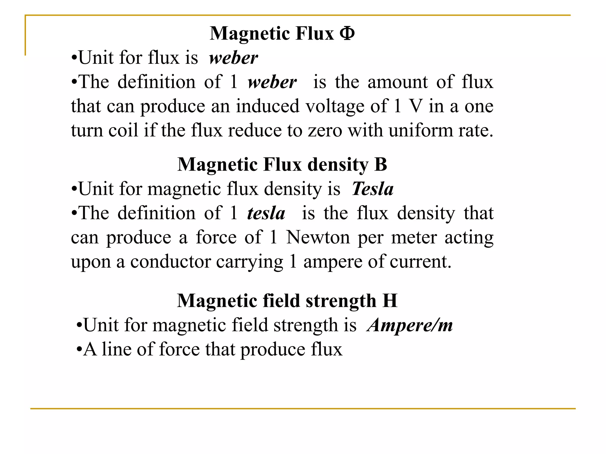
- The document discusses magnetic flux density B, magnetic flux Φ, and magnetic field strength H. It defines their units (tesla, weber, and ampere/meter respectively) and relationships between quantities.
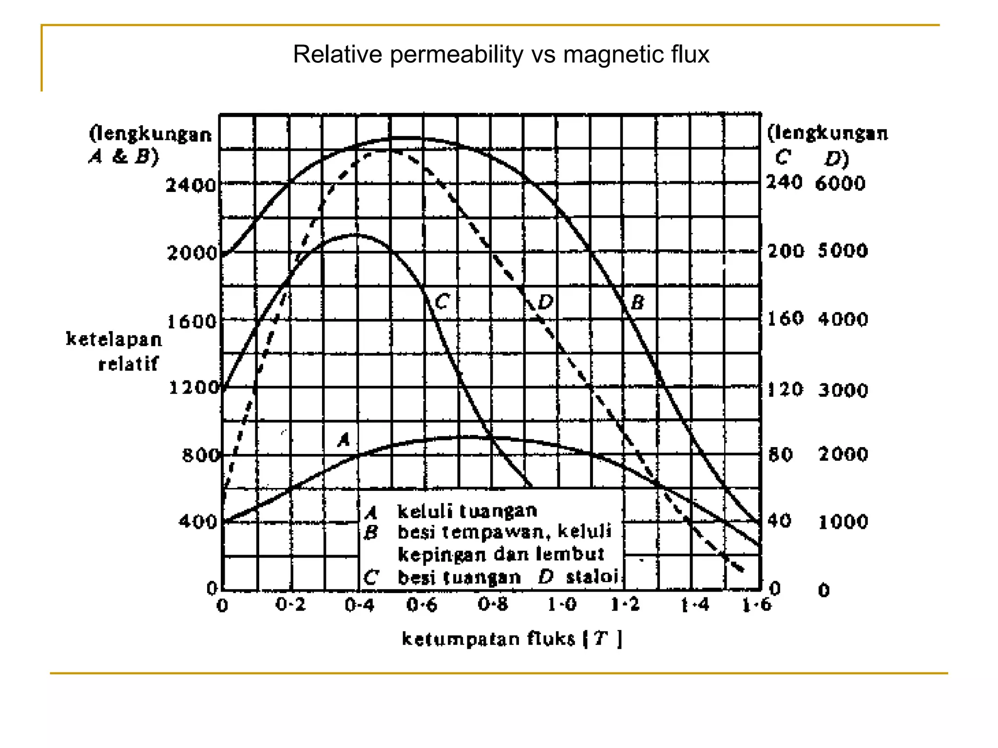
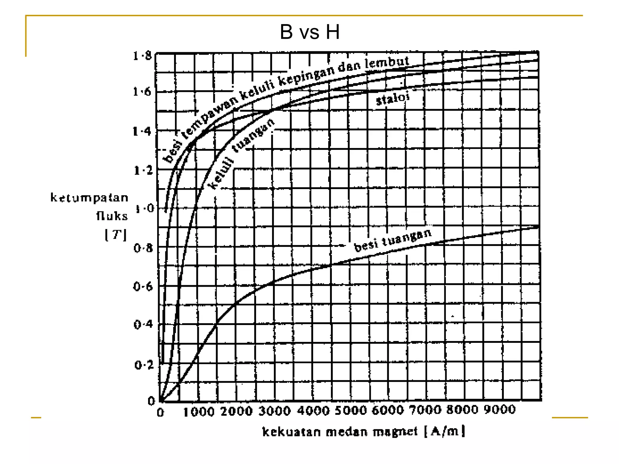
- It also discusses relative permeability and how it relates magnetic flux density B to magnetic field strength H in different materials. Lines are drawn showing trends in H and relative permeability with different materials.
- Formulas are provided relating magnetic force F, flux Φ, field strength H, and other variables. Examples are worked through applying the concepts and formulas to calculate values like flux, field strength, current, and reluctance in magnetic circuits.


![Ohm‘s law I = V/R [A]
Where I =current; V=voltage and R=resistance
And the resistance can be relate to physical parameters as
R = l /A ohm
Where =resistivity [ohm-meter], l= length in meter and A=area
of cross-section [meter square]
Analogy to the ohm‘s law
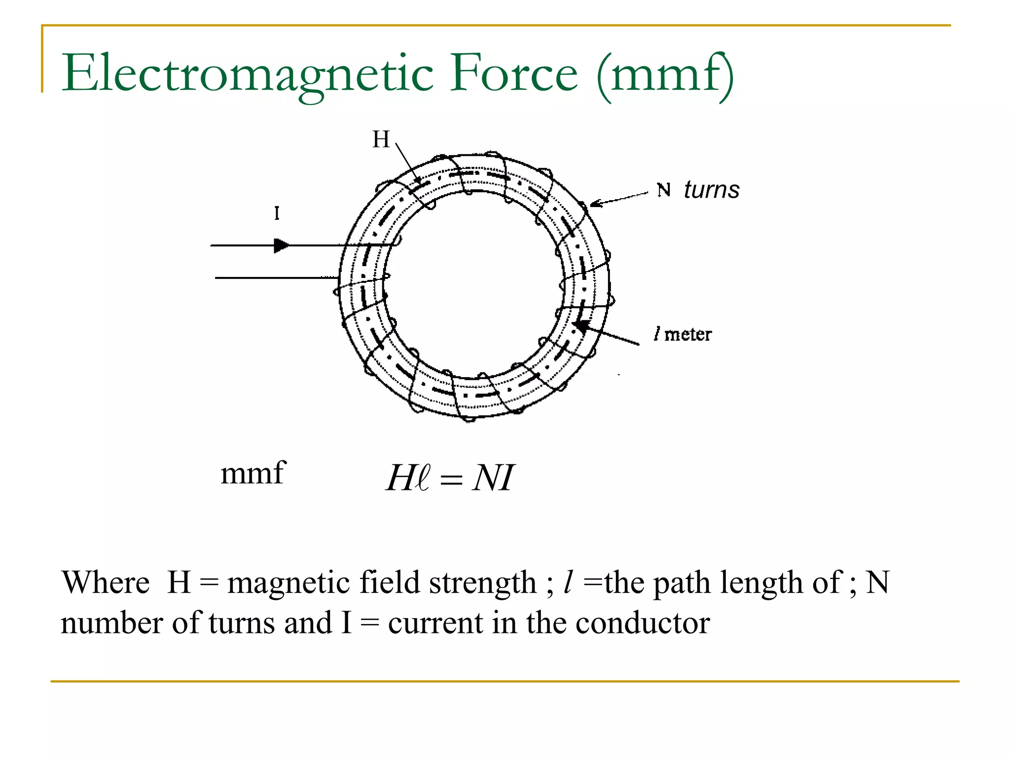
V=NI=H l I= and R=S
Reluctance ( S )
weber
S
Hl
weber
ampere
A
S
o
r
/
where](https://image.slidesharecdn.com/11magneticcircuit1-230525152449-55599156/75/11-magnetic-circuit-1-ppt-10-2048.jpg)
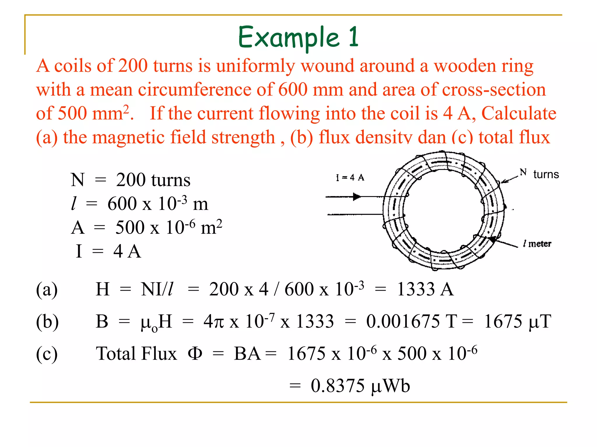
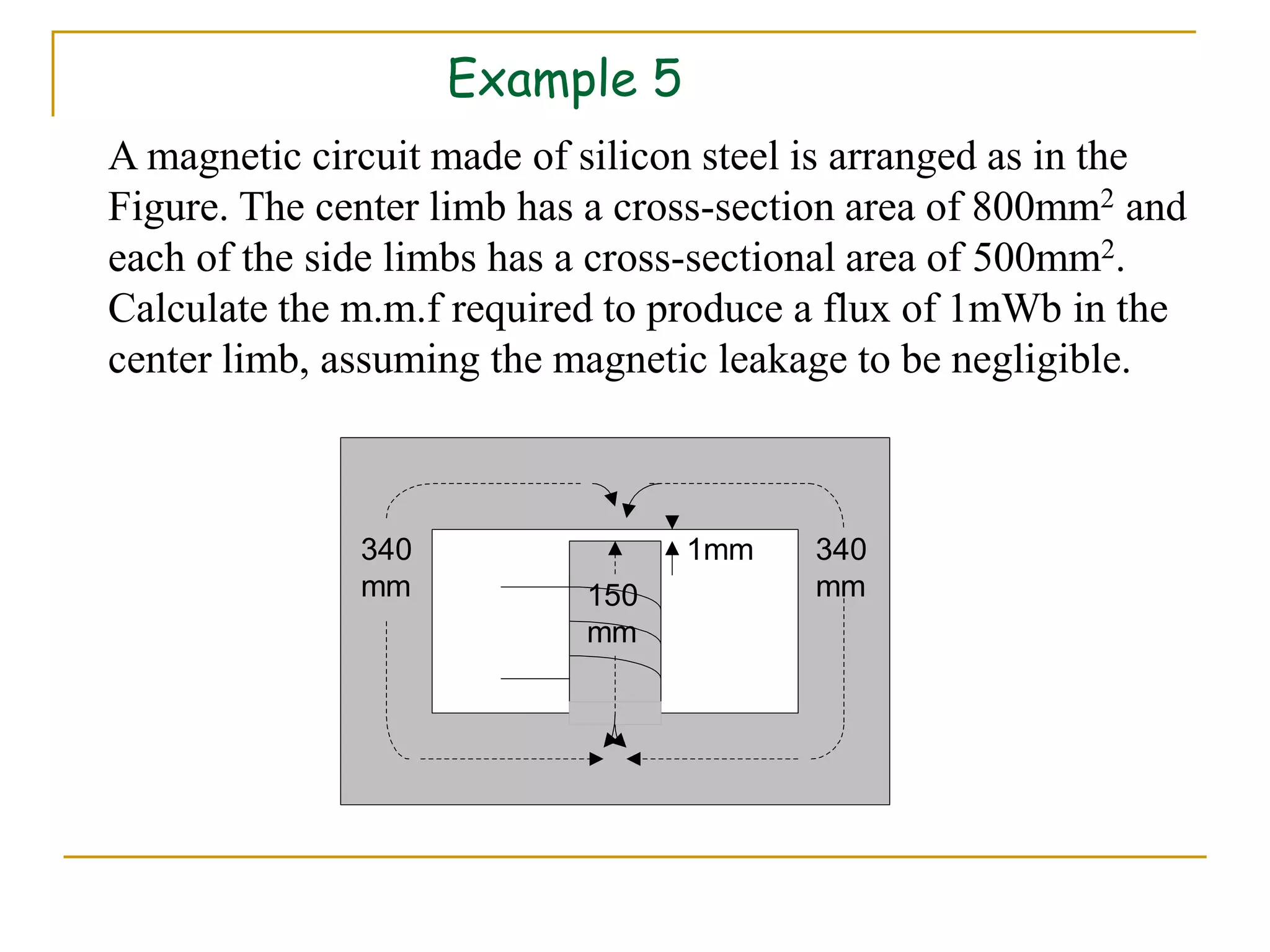
![Example 2
A mild steel ring, having a cross-section area of 500 mm2 and a
mean circumference of 400 mm is wound uniformly by a coil
of 200 turns. Calculate(a) reluctance of the ring and (b) a
current required to produce a flux of 800 Wb in the ring.
T
A
B 6
.
1
10
500
10
800
6
6
Dari graf r/B, pada B = 1.6;
r = 380
turns
4
7
10
5
10
4
380
4
.
0
A
S
o
r
]
/
[
10
667
.
1 6
Wb
A
(a)](https://image.slidesharecdn.com/11magneticcircuit1-230525152449-55599156/75/11-magnetic-circuit-1-ppt-11-2048.jpg)
![(b)
S
H
S
H
NI
A
H
]
[
1342
10
667
.
1
10
800 6
6
mmf
]
[
7
.
6
200
1342
1342
A
N
I
](https://image.slidesharecdn.com/11magneticcircuit1-230525152449-55599156/75/11-magnetic-circuit-1-ppt-12-2048.jpg)


![T
A
B
a
a 1
10
2500
10
5
.
2
6
3
]
/
[
796000
10
4
1
7
m
AT
B
H
o
a
a
factor
leakage
airgap
in
flux
flux
Total T
]
[
1594
002
.
0
796000 AT
H
mmf
Wb
003
.
0
2
.
1
0025
.
0
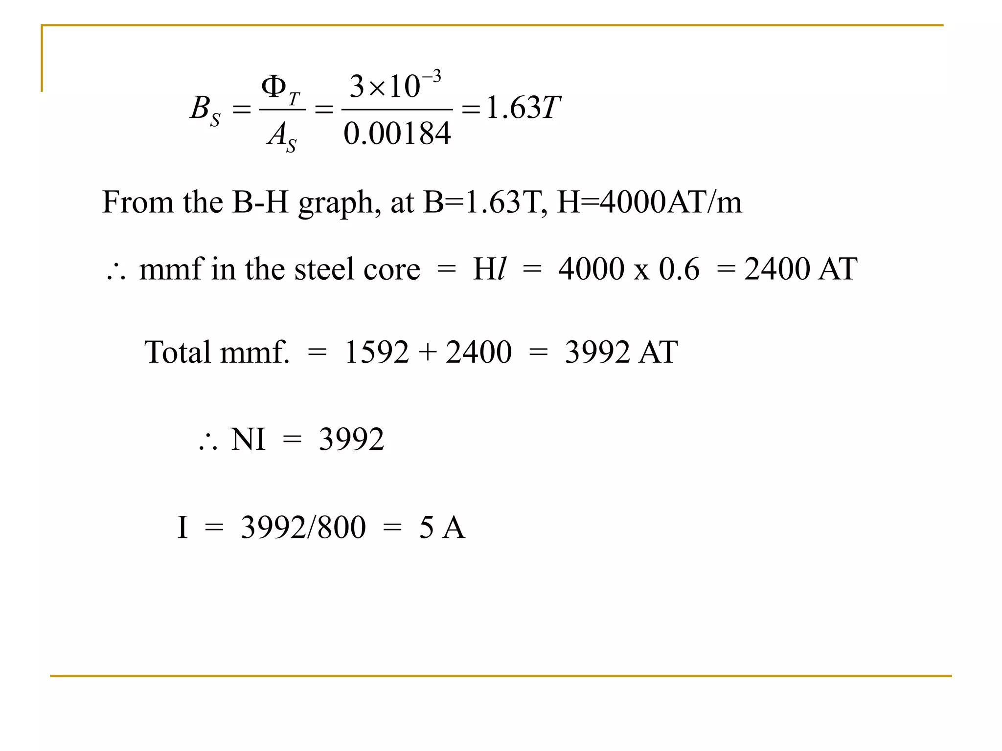
92% of the depth is laminated steel, thus the area of cross
section is
AS = 40 x 50 x 0.92 = 1840 mm2=0.00184m](https://image.slidesharecdn.com/11magneticcircuit1-230525152449-55599156/75/11-magnetic-circuit-1-ppt-19-2048.jpg)


![Coded Agents – with UiPath SDK + LangGraph [Virtual Hands-on Workshop]](https://cdn.slidesharecdn.com/ss_thumbnails/codedagentsdeck-251215155422-5497c599-thumbnail.jpg?width=640&height=640&fit=bounds)


