The document discusses DC machines and their components and operation. It covers:
1) The basic principles of electromechanical energy conversion in DC machines including generation of electromotive force through Faraday's law of induction and development of torque when current carrying conductors are placed in a magnetic field.
2) The construction of DC machines including the field system, armature, commutator, and armature windings.
3) Equations for calculating induced emf, terminal voltage, torque, and motor/generator characteristics based on the machine components and operating parameters.


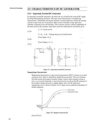


![68
Electrical Technology
so
ZP
AE
N b
φ
=
60
. . .
(3.40)
since P, Z and A are constant for a machine then
bE
N ∝
φ
or a aV I R
N
−
∝
φ
. . .
(3.41)
For a shunt motor φ is constant then
orb a aN E N V I R∝ ∝ − . . .
(3.42)
For a series motor φ is proportional to Ia
so
a
b
I
E
N α . . .
(3.43)
percentage speed regulation 100×
−
=
f
fo
N
NN
. . .
(3.44)
here No is speed at no load in RPM and Nf is speed at full load in RPM.
Example 3.2
A shunt generator delivers 50 kW at 250 volts and 400 rpm. The armature and field
resistances are 0.02 and 50 ohms respectively. Calculate the speed of the machine
running as a shunt motor and taking 50 kW input at 250 volts. Allow one volt per
brush for contact drop.
Solution
As Generator :
Line current amp200
250
1050 3
=
×
=I
Shunt field current amp5
50
250
==shI
Armature current amp2055200 =+=+= sha III
Armature drop volts1.402.0205 =×== aa RI
Induced emf dropcontactbrushdroparmature250 ++=gE
250 4.1 2 1gE = + + × [There are two brushes]
= 256.1 volts
As Motor :
Armature current amp1955200 =−=−= sha III
Armature drop volts9.302.0195 =×== aa RI
Back emf dropcontactbrushdroparmature250 −−=bE](https://image.slidesharecdn.com/unit3-140331093905-phpapp01/85/Unit-3-18-320.jpg)


![73
DC MachinesFor DC shunt motor φ is constant so T α Ia and for dc series motor φ α Ia,
so T α Ia
2
.
Example 3.3
A 125 V, dc shunt motor at its rated conditions develops 1 kW at 1800 rpm. Its line
current is 10.67 A. The motor has a field resistance of 110 ohms and armature
circuit resistance of 1.23 ohms. If the motor torque is increased by 20% determine
(i) its probable new speed, and (ii) line current.
Solution
Shunt field current amp136.1
110
125
===
sh
sh
R
V
I
Under rated conditions amp534.9136.167.101 =−=−= sha III
Torque ∝ φ Ia
For a shunt motor, φ is constant
∴ T ∝ Ia . . .
(3.63)
When the motor torque is increased by 20%, the new value of torque becomes 1.2 T
and let the new value of armature current be Ia2. We have,
1.2 T ∝ Ia2 . . .
(3.64)
Dividing Eq. (ii) by Eq. (i), we have
amp44.112.1534.9or
534.9
2.1
2
2
=×== a
a
I
I
T
T
Under rated conditions,
23.1534.912511 ×−=−= aab RIVE
or volts27.1131 =bE
But back emf ∝ speed [φ being constant]
∴ 11b NE ∝ . . .
(3.65)
with increased torque
23.144.1112522 ×−=−= aab RIVE
or 93.1102 =bE
Let the new speed be N2, then
Ebe ∝ N2 . . .
(3.66)
Dividing Eqs. (3.66) by Eq. (3.65), we have
2
2
110 93 110.93 1800
1762.8
113 27 1800 113.27
or rpm
N.
N
.
×
= = =
New speed = 1762.8 rpm and
New line current = Ia2 + Ish](https://image.slidesharecdn.com/unit3-140331093905-phpapp01/85/Unit-3-23-320.jpg)


![91
DC Machines= 330.18 Ω
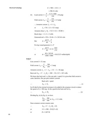
SAQ 6
Let the total resistance required (including armature resistance) in the armature
circuit to limit armature current to 40 A be R
Ω== 11
40
440
R [as Eb = 0 at starting, i.e. N = 0]
External resistance to be inserted in the armature circuit
Ω=−=− 5.95.111aRR
With this resistance present in the armature circuit the back emf developed under
steady speed.
volts2201120440440 =×−=−= RIE ab
[Since T α Ia for shunt motor and it remains constant due to constant load torque, Ia
at steady state remains same, i.e. 20 A].
Let the resistance present between the first and the second stud be r Ω. When this
resistance is cut out by moving the arm to the second stud, the resistance remaining
in the armature circuit = (R – r)
∴ 5.5
40
220440
)(40 or)given(amp =
−
=−=
−
−
rR
rR
EV b
∴ r = R – 5.5 = 11 – 5.5 = 5.5 Ω](https://image.slidesharecdn.com/unit3-140331093905-phpapp01/85/Unit-3-41-320.jpg)