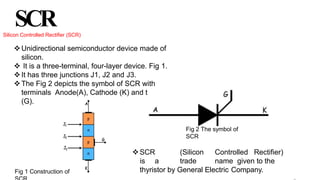
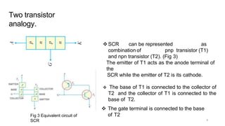
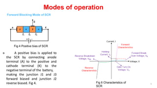
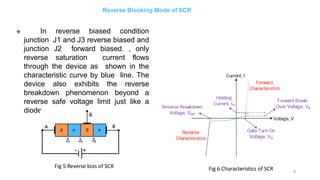
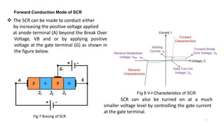
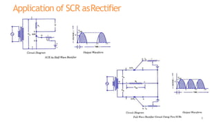
SCR (Silicon Controlled Rectifier) is a three-terminal semiconductor device made of silicon that can be represented as a combination of two transistors - a PNP and an NPN transistor. It has three modes of operation: forward blocking, reverse blocking, and forward conduction. In forward blocking mode, one junction is forward biased and two are reverse biased, allowing only leakage current. In reverse blocking mode, the biases are reversed but only reverse saturation current flows. In forward conduction mode, a gate signal or exceeding the breakover voltage allows large current flow in the forward direction. SCRs are used as rectifiers where the gate can control conduction at smaller voltages.