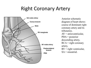
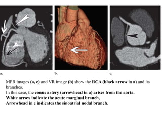
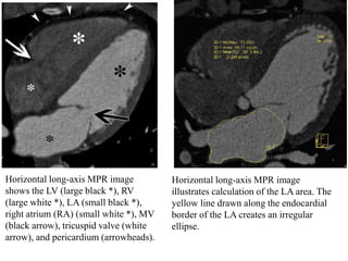
Normal Cardiac CT
OSR
Dr. Yash Kumar Achantani
Introduction
Cardiac CT is routinely performed to study cardiac and coronary
anatomy, with the advent of multidetector computed tomography (CT),
particularly with scanners having 64 or more detectors, has continued
to improve temporal resolution and allows the acquisition of isotropic
voxels.
With these scanners, the heart and coronary arteries are routinely
imaged as a motion-free volume of data.
The interpretation of cardiac CT angiographic studies performed with
multidetector scanners requires real-time interaction with the
volumetric data set that is generated.
Interpretation of the cardiac CT angiographic data is accomplished
using a combination of the postprocessing techniques.
Indications
• Non invasive evaluation of coronary artery anomalies.
• Symptomatic patients with low/moderate probability of coronary
artery disease.
• Evaluating the patency of CABG.
• New onset heart failure.
• Preop assessment of coronary arteries before non-coronary cardiac
surgery.
• New or worsening symptoms with past normal stress injury.
Technique
Building a CT Protocol
Cardiac motion separates cardiac and coronary CT from the CT
assessment of other body parts. Ultimately, successful coronary
imaging by any modality relies on the ability of the hardware (for CT,
the scanner) to produce motion-free images, or to scan faster than the
heart beats.
Thus, coronary CT relies on faster imaging or slowing cardiac motion.
The imaging speed is measured by the temporal resolution which is
determined by the CT gantry rotation time (the time required for the CT
gantry to make one full revolution).
The temporal resolution is half the gantry rotation time, owing to the
fact that image reconstruction requires CT data acquired from
approximately one-half of a gantry rotation.
Among commercially available scanners, gantry rotation times are
now as low as 330 milliseconds, yielding a temporal resolution as low
as 165 milliseconds.
Beta-blockade for Heart Rate Control
In patients who do not routinely take beta-blockers, administration of
metoprolol at the time of scanning is essential. One rule of thumb for
the target heart rate is 'the first number is a five, i.e. an ideal heart rate
between 50 and 59 beats per minute.
With cardiac monitoring, intravenous (IV) metoprolol is routinely and
safely administered by both cardiologists and radiologists 5-mg
increments given every five minutes to a total dose between 15mg and
25mg.
ECG Gating:- ECG gating refers to the simultaneous acquisition of
both the patient ECG tracing and the CT data.
CT images can be reconstructed using only a short temporal segment
periodically located in the same location of the R-wave to R-wave (R-
R) interval over multiple cardiac cycles.
Types:-
1.Prospective ECG gating
2.Retrospective ECG gating
Image Field of View
For imaging the native coronaries alone, the superior border of the
field of view should be set at the top of the carina, and the inferior
border should include the entire inferior wall of the heart.
Ideally, the planned field of view should include several slices of the
liver to account for cardiac displacement during breath-holding.
Because the CT acquisition is in the craniocaudal direction, obtaining a
small amount of CT data inferior to the heart does not affect image
quality.
Contrast
Uses iodinated contrast, with high iodine flux to maximize the peak
enhancement.
Fast injection rate (5-7ml/sec) through a 18 G access.
Types
Biphasic injection:- Two injectors ( one with contrast and one with
saline).
First phase- Injects full strength contrast at (4-5ml/sec)
Second phase- Saline flush (50 ml @ 4-5ml/sec) to clear Subclavian
vein, SVC, and RA of dense contrast.
Triphasic injection:- Two injectors ( one with contrast and one with
saline).
First phase- 50-70 ml full strength contrast at (4-5ml/sec)
Second phase- 50 ml of mixed 70% saline and 30% contrast @ 4-
5ml/sec.
Third phase- 50 ml saline flush @ 5ml/sec
Post Processing
A variety of post processing techniques, allow non invasive assessment
of every aspect of the cardiovascular system.
These include
 Multiplanar reformation (MPR),
 Maximum intensity projection (MIP),
 Volume rendering (VR),
 Curved reformation,
 Cine imaging.
MPR
MPR is the basic tool used to interpret cardiac CT angiographic studies.
The multiplanar capabilities of the workstation allow images of the
heart and coronary arteries to be manually rotated for optimal
evaluation of the cardiac anatomy.
Most workstations with cardiac analysis capabilities can automatically
orient volumetric image data sets along the cardiac axes and into the
traditionally used cardiac planes (ie, short-axis, horizontal long-axis,
vertical long-axis).
MIP
MIP is a postprocessing technique that takes the highest-attenuation
voxel in a predetermined slab of data and projects it from the user
toward the viewing screen, resulting in a two-dimensional image.
Only the highest-attenuation objects, typically contrast material and
bone, are preferentially displayed and retained in the image.
The limitation of MIP images is that they lack depth and spatial
information regarding relationships to adjacent structures.
VR
VR is a 3D technique in which the CT attenuation values for each voxel
can be assigned a specific color thereby producing an overall image of
the heart.
VR is the only true 3D technique and provides the depth and spatial
information that is lacking with MIP.
VR techniques facilitate surface evaluation of the heart and coronary
arteries.
Curved Reformation
Because normal coronary arteries are often tortuous, accurate
evaluation requires assessment of the entire vessel along its center line.
Curved reformatted images provide this capability by sampling a given
volume (ie, artery) along a predefined curved anatomic plane.
This type of reformation is especially helpful in patients with bypass
grafts and highly tortuous coronary arteries.
Cine Imaging
Cine images are used to examine the motion and physiologic features
of cardiac structures such as the LV and cardiac valves.
This approach is particularly useful for examining
LV wall motion and wall thickening and for assessing valve motion in
multiple planes. Assessment of myocardial contractility,
Determination of quantitative LV functional parameters, including end-
diastolic and end-systolic ventricular volumes, stroke volume, and
ejection fraction.
Coronary Arteries
Left Coronary Artery
Dominant left
coronary artery anatomy.
Left anterior oblique
schematic diagram of
dominant left coronary
artery anatomy, including
left anterior descending
artery and left circumflex
artery tributaries,
is shown.
AVGA = atrioventricular
groove artery,
PDA = posterior descending
artery.
The left coronary artery (LCA) normally arises from the left sinus of
Valsalva near the sinotubular ridge.
It courses for a variable distance before giving rise to the LAD artery
and the LCx artery.
(a) Axial MPR image displays the origin of the coronary arteries from the
aorta. The LCA (black arrow) bifurcates into the left anterior descending
(LAD) artery (white arrowhead) and the left circumflex (LCx) artery (black
arrowhead). White arrow indicates the right coronary artery (RCA).
(b) VR image shows the LCA (black arrow) arising from the aorta and
bifurcating into the proximal LCx artery (arrowhead) and the proximal LAD
artery (white arrow).
The LAD artery courses anterolaterally in the epicardial fat of the
anterior interventricular groove and supplies the majority of the LV.
The major branches of the LAD artery are the diagonal and septal
perforating arteries.
The diagonal branches course laterally and predominantly supply the LV
free wall.
The septal branches course medially and supply the majority of the
interventricular septum, as well as the atrioventricular (AV) bundle and
proximal bundle branch.
Oblique axial (a) and vertical long-axis (b) MPR images show the normal
LAD artery (arrows) coursing in the epicardial fat of the interventricular
groove toward the LV apex.
Oblique axial MPR (a) and VR (b) images show the septal branches
(black arrowheads) and diagonal branches (white arrowheads) of the
LAD artery. The septal branches quickly reach and penetrate the myocardium,
whereas the diagonal branches course laterally to the LV free wall.
The LCx artery is the other major branch of the LCA. It courses in the
left AV groove, giving rise to obtuse marginal branches, sometimes
referred to as lateral branches.
The LCx artery and its branches supply the LV free wall and a variable
portion of the anterolateral papillary muscle.
It variably gives rise to posterolateral and posterior descending artery
(PDA) branches supplying the diaphragmatic portion of the LV.
Oblique axial MPR (a) and VR (b) images show the LCx artery (black
arrow) and obtuse marginal branches (white arrows).
In approximately 15% of patients, a third branch, the ramus
intermedius (RI) branch, arises at the division of the LCA, resulting in
a trifurcation.
When present, the RI branch courses laterally toward the LV free wall.
Its course is similar to that of a diagonal branch of the LAD artery.
(a) Oblique axial MPR image shows the RI branch (arrow) arising between
the LAD artery (black arrowhead) and the LCx artery (white
arrowhead), resulting in a trifurcation of the LCA.
(b) VR image shows the RI branch (arrow) arising from the trifurcation.
Black arrowhead indicates the LAD artery, white arrowhead indicates the
LCx artery.
Right Coronary Artery
Anterior schematic
diagram of heart shows
course of dominant right
coronary artery and its
tributaries.
AV = atrioventricular,
PDA = posterior
descending artery,
RCA = right coronary
artery,
RV = right ventricular,
SA = sinoatrial.
The RCA normally arises from the right coronary sinus (CS) and
courses in the right AV groove toward the crux of the heart (the point
on the posterior surface of the heart where the AV groove transects the
line of the interventricular septum and interatrial septum, forming a
cross).
In approximately 50%–60% of patients, the first branch of the RCA is a
conus artery. The conus artery can also arise directly from the aorta
(30%–35% of patients).
The conus artery supplies the RV outflow tract (conus arteriosis) and
forms the circle of Vieussens, an anastomosis with the LAD arterial
circulation.
MPR images (a, c) and VR image (b) show the RCA (black arrow in a) and its
branches.
In this case, the conus artery (arrowhead in a) arises from the aorta.
White arrow indicate the acute marginal branch,
Arrowhead in c indicates the sinoatrial nodal branch.
In approximately 58% of patients, the sinoatrial nodal artery arises
from the RCA; in the remaining patients (42%), it arises from the LCx
artery.
Multiple ventricular branches arise from the RCA, the largest of which
is called the acute marginal branch.
Dominance
The coronary artery that gives rise to the PDA and posterolateral
branch is referred to as the “dominant” artery, with the RCA being
dominant in approximately 70% of cases.
The LCA is dominant in approximately 10% of cases, supplying the
entire LV, accompanied by the PDA and posterolateral branches from
the LCx artery.
In the remaining cases, the RCA and LCA are codominant; that is,
portions of the LV diaphragmatic wall are supplied by both the RCA
and the LCx artery.
The length of the distal RCA is inversely proportional to the length of
the LCA along the inferior aspect of the heart. The RCA is typically
diminutive compared with the LCx artery in patients with left-dominant
systems.
(a) VR image shows the inferior surface of the heart. A right-dominant system
is depicted, with the PDA (white arrowhead) arising from the RCA (black
arrowhead). A posterolateral branch (arrow) is also seen.
(b) VR image shows a codominant system, with the inferior myocardial surface
supplied equally by the RCA and the LCx artery.
(c) Coronal MPR image shows a left-
dominant system, with the RCA being
smaller than normal.
Segmental Coronary Arterial Anatomy
A classification scheme that divides the coronary arteries into segments
based on specific anatomic structures and arterial branches.
Left Coronary Artery.—The LCA extends from the ostium to its bi- or
trifurcation.
LAD Artery.—The LAD artery is divided into proximal, middle, and
distal portions.
Proximal LAD artery extends from the left main bifurcation to the
origin of the first septal branch.
Mid portion of the LAD artery extends to the point where the artery
forms an acute angle, which may coincide with the origin of the second
septal perforator.
The apical segment represents the termination of the artery.
LCx Artery.—The LCx artery is divided into proximal and distal
segments, based on the origin of the (usually large) obtuse marginal
branches.
Right Coronary Artery.—The proximal RCA extends from the ostium
to a point halfway to the acute margin of the heart.
The mid-RCA represents the other half of that distance.
The distal RCA courses along the posterior AV groove, from the acute
angle of the heart to the origin of the PDA.
VR images show the left segmental coronary arterial anatomy
show the superior (left) and anterolateral (right) aspects of the heart, including
Left marginal vein (large white arrow),
LCx (large black arrowhead),
LAD (large white arrowhead),
LAD (black arrow),
LAD (small black arrowhead),
LAD (small white arrow), and
LAD (small white arrowhead).
VR images show the right (b) segmental coronary arterial anatomy
Shows the right (left) and inferior (middle and right) aspects of the heart, including
RCA (black arrow),
RCA (large white arrowhead),
RCA (white arrow),
RCA (black arrowhead), and
RCA (small white arrowhead)
Normal Coronary Artery Diameter
The average size varies with gender (approximately 3 mm in females
and 4 mm in males)
The average diameters of each coronary artery also vary, ranging from
5 mm (LCA in males) to 2 mm (PDA in females)
Focal abnormal dilatation to more than 1.5 times the diameter of an
adjacent normal coronary artery is defined as an aneurysm. If the
process is diffuse, it is known as ectasia.
Other Cardiac Structures
Evaluation of MPR images in combination with use of these routine
cardiac imaging planes allows comprehensive evaluation of cardiac
anatomy and function.
Cardiac Imaging Planes
and the Left Side of the Heart
Vertical Long-Axis View:- is a parasagittal plane oriented along the
long axis of the LV lumen.
The relationship between the left atrium (LA) and the LV is assessed
on vertical long-axis images.
The inferior and anterior walls of the LV myocardium are optimized on
this view.
The structure and function of the bicuspid MV and LV are well
demonstrated on vertical long-axis cine images, and the LA appendage
and CS are routinely depicted.
Vertical long-axis MPR image shows the
LV (black *),
LA (white *),
LA appendage (white arrow),
Mitral valve (MV) (black arrow), and
CS (arrowhead).
Horizontal Long-Axis View.—The horizontal long-axis view, or four-
chamber view, is a horizontal plane through the heart that essentially
bisects all four cardiac chambers.
The resultant display readily allows assessment of chamber size and
valve position. The septal, apical, and lateral LV walls can be
simultaneously assessed.
The lateral wall of the LV is normally thin at the apex (typically 1–2
mm), even in abnormally thickened hearts.
Subjective evaluation of AV valvular and ventricular function is usually
also possible in cine mode.
LA size can readily be determined. An area of less than 20 cm2 is
normal, 20–30 cm2 is mildly abnormal, 30–40 cm2 is moderately
abnormal, and greater than 40 cm2 is severely abnormal
Horizontal long-axis MPR image
shows the LV (large black *), RV
(large white *), LA (small black *),
right atrium (RA) (small white *), MV
(black arrow), tricuspid valve (white
arrow), and pericardium (arrowheads).
Horizontal long-axis MPR image
illustrates calculation of the LA area. The
yellow line drawn along the endocardial
border of the LA creates an irregular
ellipse.
Three-Chamber View.—The three-chamber view is an oblique long-
axis view that optimizes visualization of the LV, LA, aortic root, MV,
and aortic valve.
The three chamber view allows evaluation of the LV outflow tract,
aortic valve, aortic root, and proximal ascending thoracic aorta.
The posteromedial papillary muscles are often seen arising from the LV
free (lateral) wall on this view.
Three-chamber MPR image shows the
LV papillary muscles (arrow) and
chordae tendineae (arrowheads).
Coronal MPR image shows the LV
papillary muscles (arrows).
Short-Axis View.—The short-axis view is obtained in an oblique
coronal plane relative to the thorax, down the barrel of the LV lumen.
As one progresses from the MV toward the apex in the short axis, the
basal, middle, and apical portions of the LV myocardium can be
evaluated.
This plane allows easy assessment of LV size and myocardial
contractility.
Short-axis MPR image shows the
mid-RV (white *) and
mid-LV (black *).
Right Side of the Heart
Depending on the injection protocol used, varying levels of
enhancement of the right side of the heart are achieved. If this side of
the heart is enhanced with contrast material, the RA, RV, and tricuspid
valves can be assessed in detail.
The eustachian valve is located at the RA–inferior vena cava junction
and directs flow toward the foramen ovale.
The thebesian valve prevents reflux from the RA into the CS.
(16) Sagittal MPR image shows the inferior vena cava (arrowhead),
superior vena cava (arrow), LA (black *), RA (white*).
(17) MPR image shows the CS (arrow) entering the RA (white *).
The normal thebesian valve (arrowhead) and the LA (black *) are also depicted.
The RV is the most anterior of the cardiac chambers and has a heavily
trabeculated apex, The smooth, muscular infundibulum (or conus) of the
RV is the outflow portion of the RV directly inferior to the pulmonary
valve.
A characteristic feature of the RV is the moderator band, a muscular
band extending from the interventricular septum to the base of the
anterior papillary muscle.
The moderator band is part of the right bundle branch conduction
system.
Although the moderator band and the heavily trabeculated apex are
distinct features of the RV, other features such as a well-developed
infundibulum, septal papillary muscles, and lack of fibrous continuity of
the AV valve and outflow tract are key to differentiating the RV from the
LV.
(18) Oblique MPR images show the RA (black arrow in a),
RV outflow tract (black *), and pulmonary valve (arrowhead).
The LA (white *) and the aorta (white arrow in a, arrow in b) are also seen.
(19) Three-chamber MPR image shows the RV moderator band (arrow).
Atrial Appendages
In most adults (97%), the LA appendages have pectinate muscles
measuring greater than 1 mm. These muscles are continuous fibers
running parallel to each other within the LA appendage.
The RA appendage also has pectinate muscles, although they are
slightly larger than those of the LA appendage.
The LA appendage arises from the superolateral aspect of the LA and
projects anteriorly over the proximal LCx artery.
It is more tubular than the normally pyramidal RA appendage and has a
narrower base
Cardiac Valves
The four cardiac valves are routinely imaged during cardiac CT
angiography, and their motion and morphologic characteristics should
also be assessed at all cardiac CT angiographic examinations with
reconstructed and cine images.
The MV separates the LA from the LV. It is normally connected to the
morphologic LV.
The MV is composed of two leaflets, the anterior and posterior leaflets;
the other valves normally have three leaflets.
The MV annulus, or valve ring, is part of the cardiac skeleton and is
imbedded in the myocardium..
The papillary muscles with their chordae tendineae are also a
component of the MV apparatus.
The tricuspid valve separates the RA from the RV and is composed of
the same structures as the MV: leaflets, annulus, commissures, papillary
muscles, and chordae tendineae.
It is normally connected to the morphologic RV.
It is separated from the pulmonary valve by the crista
supraventricularis—a muscular ridge—unlike the MV, which shares a
fibrous continuity with the aortic valve.
The aortic valve separates the LV outflow tract from the ascending
aorta. It is composed of an annulus, cusps, and commissures. The three
cusps of the aortic valve form pocketlike outpouchings that are
designed to direct blood into the sinuses of Valsalva during diastole.
The pulmonary valve separates the RV outflow tract from the main
pulmonary artery and has three leaflets.
Axial MPR image (supero-inferior view) demonstrates the aortic
valve and its cusps in relation to the LA. These cusps are the right
coronary cusp (white *), the left coronary cusp (black *), and the
noncoronary cusp (box).
Pericardium
The pericardium is normally paper thin, measuring 2 mm or less.
Multidetector CT routinely depicts the fluid-filled junctions of the
visceral and parietal pericardia, which form recesses and sinuses.
The oblique and transverse sinuses are two of the most commonly
encountered sinuses at multidetector CT of the heart and thorax and are
continuous with the pericardial cavity.
On an axial MPR image obtained inferior to the right pulmonary artery, the
transverse sinus (black arrow) is posterior to the ascending aorta (AA) and the
main pulmonary artery (PA) and superior to the LA.
The oblique sinus (white arrow) is posterior to the LA and is always separated
from the transverse sinus by a fat plane.
Cardiac CT

Cardiac CT

  • 1.
    Normal Cardiac CT OSR Dr.Yash Kumar Achantani
  • 2.
    Introduction Cardiac CT isroutinely performed to study cardiac and coronary anatomy, with the advent of multidetector computed tomography (CT), particularly with scanners having 64 or more detectors, has continued to improve temporal resolution and allows the acquisition of isotropic voxels. With these scanners, the heart and coronary arteries are routinely imaged as a motion-free volume of data. The interpretation of cardiac CT angiographic studies performed with multidetector scanners requires real-time interaction with the volumetric data set that is generated. Interpretation of the cardiac CT angiographic data is accomplished using a combination of the postprocessing techniques.
  • 3.
    Indications • Non invasiveevaluation of coronary artery anomalies. • Symptomatic patients with low/moderate probability of coronary artery disease. • Evaluating the patency of CABG. • New onset heart failure. • Preop assessment of coronary arteries before non-coronary cardiac surgery. • New or worsening symptoms with past normal stress injury.
  • 4.
    Technique Building a CTProtocol Cardiac motion separates cardiac and coronary CT from the CT assessment of other body parts. Ultimately, successful coronary imaging by any modality relies on the ability of the hardware (for CT, the scanner) to produce motion-free images, or to scan faster than the heart beats. Thus, coronary CT relies on faster imaging or slowing cardiac motion. The imaging speed is measured by the temporal resolution which is determined by the CT gantry rotation time (the time required for the CT gantry to make one full revolution).
  • 5.
    The temporal resolutionis half the gantry rotation time, owing to the fact that image reconstruction requires CT data acquired from approximately one-half of a gantry rotation. Among commercially available scanners, gantry rotation times are now as low as 330 milliseconds, yielding a temporal resolution as low as 165 milliseconds. Beta-blockade for Heart Rate Control In patients who do not routinely take beta-blockers, administration of metoprolol at the time of scanning is essential. One rule of thumb for the target heart rate is 'the first number is a five, i.e. an ideal heart rate between 50 and 59 beats per minute. With cardiac monitoring, intravenous (IV) metoprolol is routinely and safely administered by both cardiologists and radiologists 5-mg increments given every five minutes to a total dose between 15mg and 25mg.
  • 6.
    ECG Gating:- ECGgating refers to the simultaneous acquisition of both the patient ECG tracing and the CT data. CT images can be reconstructed using only a short temporal segment periodically located in the same location of the R-wave to R-wave (R- R) interval over multiple cardiac cycles. Types:- 1.Prospective ECG gating 2.Retrospective ECG gating
  • 9.
    Image Field ofView For imaging the native coronaries alone, the superior border of the field of view should be set at the top of the carina, and the inferior border should include the entire inferior wall of the heart. Ideally, the planned field of view should include several slices of the liver to account for cardiac displacement during breath-holding. Because the CT acquisition is in the craniocaudal direction, obtaining a small amount of CT data inferior to the heart does not affect image quality.
  • 10.
    Contrast Uses iodinated contrast,with high iodine flux to maximize the peak enhancement. Fast injection rate (5-7ml/sec) through a 18 G access. Types Biphasic injection:- Two injectors ( one with contrast and one with saline). First phase- Injects full strength contrast at (4-5ml/sec) Second phase- Saline flush (50 ml @ 4-5ml/sec) to clear Subclavian vein, SVC, and RA of dense contrast.
  • 11.
    Triphasic injection:- Twoinjectors ( one with contrast and one with saline). First phase- 50-70 ml full strength contrast at (4-5ml/sec) Second phase- 50 ml of mixed 70% saline and 30% contrast @ 4- 5ml/sec. Third phase- 50 ml saline flush @ 5ml/sec
  • 12.
    Post Processing A varietyof post processing techniques, allow non invasive assessment of every aspect of the cardiovascular system. These include  Multiplanar reformation (MPR),  Maximum intensity projection (MIP),  Volume rendering (VR),  Curved reformation,  Cine imaging.
  • 13.
    MPR MPR is thebasic tool used to interpret cardiac CT angiographic studies. The multiplanar capabilities of the workstation allow images of the heart and coronary arteries to be manually rotated for optimal evaluation of the cardiac anatomy. Most workstations with cardiac analysis capabilities can automatically orient volumetric image data sets along the cardiac axes and into the traditionally used cardiac planes (ie, short-axis, horizontal long-axis, vertical long-axis).
  • 14.
    MIP MIP is apostprocessing technique that takes the highest-attenuation voxel in a predetermined slab of data and projects it from the user toward the viewing screen, resulting in a two-dimensional image. Only the highest-attenuation objects, typically contrast material and bone, are preferentially displayed and retained in the image. The limitation of MIP images is that they lack depth and spatial information regarding relationships to adjacent structures.
  • 15.
    VR VR is a3D technique in which the CT attenuation values for each voxel can be assigned a specific color thereby producing an overall image of the heart. VR is the only true 3D technique and provides the depth and spatial information that is lacking with MIP. VR techniques facilitate surface evaluation of the heart and coronary arteries.
  • 16.
    Curved Reformation Because normalcoronary arteries are often tortuous, accurate evaluation requires assessment of the entire vessel along its center line. Curved reformatted images provide this capability by sampling a given volume (ie, artery) along a predefined curved anatomic plane. This type of reformation is especially helpful in patients with bypass grafts and highly tortuous coronary arteries.
  • 17.
    Cine Imaging Cine imagesare used to examine the motion and physiologic features of cardiac structures such as the LV and cardiac valves. This approach is particularly useful for examining LV wall motion and wall thickening and for assessing valve motion in multiple planes. Assessment of myocardial contractility, Determination of quantitative LV functional parameters, including end- diastolic and end-systolic ventricular volumes, stroke volume, and ejection fraction.
  • 19.
  • 20.
    Left Coronary Artery Dominantleft coronary artery anatomy. Left anterior oblique schematic diagram of dominant left coronary artery anatomy, including left anterior descending artery and left circumflex artery tributaries, is shown. AVGA = atrioventricular groove artery, PDA = posterior descending artery.
  • 21.
    The left coronaryartery (LCA) normally arises from the left sinus of Valsalva near the sinotubular ridge. It courses for a variable distance before giving rise to the LAD artery and the LCx artery.
  • 22.
    (a) Axial MPRimage displays the origin of the coronary arteries from the aorta. The LCA (black arrow) bifurcates into the left anterior descending (LAD) artery (white arrowhead) and the left circumflex (LCx) artery (black arrowhead). White arrow indicates the right coronary artery (RCA). (b) VR image shows the LCA (black arrow) arising from the aorta and bifurcating into the proximal LCx artery (arrowhead) and the proximal LAD artery (white arrow).
  • 23.
    The LAD arterycourses anterolaterally in the epicardial fat of the anterior interventricular groove and supplies the majority of the LV. The major branches of the LAD artery are the diagonal and septal perforating arteries. The diagonal branches course laterally and predominantly supply the LV free wall. The septal branches course medially and supply the majority of the interventricular septum, as well as the atrioventricular (AV) bundle and proximal bundle branch.
  • 24.
    Oblique axial (a)and vertical long-axis (b) MPR images show the normal LAD artery (arrows) coursing in the epicardial fat of the interventricular groove toward the LV apex.
  • 25.
    Oblique axial MPR(a) and VR (b) images show the septal branches (black arrowheads) and diagonal branches (white arrowheads) of the LAD artery. The septal branches quickly reach and penetrate the myocardium, whereas the diagonal branches course laterally to the LV free wall.
  • 26.
    The LCx arteryis the other major branch of the LCA. It courses in the left AV groove, giving rise to obtuse marginal branches, sometimes referred to as lateral branches. The LCx artery and its branches supply the LV free wall and a variable portion of the anterolateral papillary muscle. It variably gives rise to posterolateral and posterior descending artery (PDA) branches supplying the diaphragmatic portion of the LV.
  • 27.
    Oblique axial MPR(a) and VR (b) images show the LCx artery (black arrow) and obtuse marginal branches (white arrows).
  • 28.
    In approximately 15%of patients, a third branch, the ramus intermedius (RI) branch, arises at the division of the LCA, resulting in a trifurcation. When present, the RI branch courses laterally toward the LV free wall. Its course is similar to that of a diagonal branch of the LAD artery.
  • 29.
    (a) Oblique axialMPR image shows the RI branch (arrow) arising between the LAD artery (black arrowhead) and the LCx artery (white arrowhead), resulting in a trifurcation of the LCA. (b) VR image shows the RI branch (arrow) arising from the trifurcation. Black arrowhead indicates the LAD artery, white arrowhead indicates the LCx artery.
  • 30.
    Right Coronary Artery Anteriorschematic diagram of heart shows course of dominant right coronary artery and its tributaries. AV = atrioventricular, PDA = posterior descending artery, RCA = right coronary artery, RV = right ventricular, SA = sinoatrial.
  • 31.
    The RCA normallyarises from the right coronary sinus (CS) and courses in the right AV groove toward the crux of the heart (the point on the posterior surface of the heart where the AV groove transects the line of the interventricular septum and interatrial septum, forming a cross). In approximately 50%–60% of patients, the first branch of the RCA is a conus artery. The conus artery can also arise directly from the aorta (30%–35% of patients). The conus artery supplies the RV outflow tract (conus arteriosis) and forms the circle of Vieussens, an anastomosis with the LAD arterial circulation.
  • 32.
    MPR images (a,c) and VR image (b) show the RCA (black arrow in a) and its branches. In this case, the conus artery (arrowhead in a) arises from the aorta. White arrow indicate the acute marginal branch, Arrowhead in c indicates the sinoatrial nodal branch.
  • 33.
    In approximately 58%of patients, the sinoatrial nodal artery arises from the RCA; in the remaining patients (42%), it arises from the LCx artery. Multiple ventricular branches arise from the RCA, the largest of which is called the acute marginal branch.
  • 34.
    Dominance The coronary arterythat gives rise to the PDA and posterolateral branch is referred to as the “dominant” artery, with the RCA being dominant in approximately 70% of cases. The LCA is dominant in approximately 10% of cases, supplying the entire LV, accompanied by the PDA and posterolateral branches from the LCx artery. In the remaining cases, the RCA and LCA are codominant; that is, portions of the LV diaphragmatic wall are supplied by both the RCA and the LCx artery. The length of the distal RCA is inversely proportional to the length of the LCA along the inferior aspect of the heart. The RCA is typically diminutive compared with the LCx artery in patients with left-dominant systems.
  • 35.
    (a) VR imageshows the inferior surface of the heart. A right-dominant system is depicted, with the PDA (white arrowhead) arising from the RCA (black arrowhead). A posterolateral branch (arrow) is also seen. (b) VR image shows a codominant system, with the inferior myocardial surface supplied equally by the RCA and the LCx artery.
  • 36.
    (c) Coronal MPRimage shows a left- dominant system, with the RCA being smaller than normal.
  • 37.
    Segmental Coronary ArterialAnatomy A classification scheme that divides the coronary arteries into segments based on specific anatomic structures and arterial branches. Left Coronary Artery.—The LCA extends from the ostium to its bi- or trifurcation. LAD Artery.—The LAD artery is divided into proximal, middle, and distal portions. Proximal LAD artery extends from the left main bifurcation to the origin of the first septal branch. Mid portion of the LAD artery extends to the point where the artery forms an acute angle, which may coincide with the origin of the second septal perforator. The apical segment represents the termination of the artery.
  • 38.
    LCx Artery.—The LCxartery is divided into proximal and distal segments, based on the origin of the (usually large) obtuse marginal branches. Right Coronary Artery.—The proximal RCA extends from the ostium to a point halfway to the acute margin of the heart. The mid-RCA represents the other half of that distance. The distal RCA courses along the posterior AV groove, from the acute angle of the heart to the origin of the PDA.
  • 39.
    VR images showthe left segmental coronary arterial anatomy show the superior (left) and anterolateral (right) aspects of the heart, including Left marginal vein (large white arrow), LCx (large black arrowhead), LAD (large white arrowhead), LAD (black arrow), LAD (small black arrowhead), LAD (small white arrow), and LAD (small white arrowhead).
  • 40.
    VR images showthe right (b) segmental coronary arterial anatomy Shows the right (left) and inferior (middle and right) aspects of the heart, including RCA (black arrow), RCA (large white arrowhead), RCA (white arrow), RCA (black arrowhead), and RCA (small white arrowhead)
  • 41.
    Normal Coronary ArteryDiameter The average size varies with gender (approximately 3 mm in females and 4 mm in males) The average diameters of each coronary artery also vary, ranging from 5 mm (LCA in males) to 2 mm (PDA in females) Focal abnormal dilatation to more than 1.5 times the diameter of an adjacent normal coronary artery is defined as an aneurysm. If the process is diffuse, it is known as ectasia.
  • 42.
    Other Cardiac Structures Evaluationof MPR images in combination with use of these routine cardiac imaging planes allows comprehensive evaluation of cardiac anatomy and function.
  • 43.
    Cardiac Imaging Planes andthe Left Side of the Heart Vertical Long-Axis View:- is a parasagittal plane oriented along the long axis of the LV lumen. The relationship between the left atrium (LA) and the LV is assessed on vertical long-axis images. The inferior and anterior walls of the LV myocardium are optimized on this view. The structure and function of the bicuspid MV and LV are well demonstrated on vertical long-axis cine images, and the LA appendage and CS are routinely depicted.
  • 44.
    Vertical long-axis MPRimage shows the LV (black *), LA (white *), LA appendage (white arrow), Mitral valve (MV) (black arrow), and CS (arrowhead).
  • 45.
    Horizontal Long-Axis View.—Thehorizontal long-axis view, or four- chamber view, is a horizontal plane through the heart that essentially bisects all four cardiac chambers. The resultant display readily allows assessment of chamber size and valve position. The septal, apical, and lateral LV walls can be simultaneously assessed. The lateral wall of the LV is normally thin at the apex (typically 1–2 mm), even in abnormally thickened hearts. Subjective evaluation of AV valvular and ventricular function is usually also possible in cine mode. LA size can readily be determined. An area of less than 20 cm2 is normal, 20–30 cm2 is mildly abnormal, 30–40 cm2 is moderately abnormal, and greater than 40 cm2 is severely abnormal
  • 46.
    Horizontal long-axis MPRimage shows the LV (large black *), RV (large white *), LA (small black *), right atrium (RA) (small white *), MV (black arrow), tricuspid valve (white arrow), and pericardium (arrowheads). Horizontal long-axis MPR image illustrates calculation of the LA area. The yellow line drawn along the endocardial border of the LA creates an irregular ellipse.
  • 47.
    Three-Chamber View.—The three-chamberview is an oblique long- axis view that optimizes visualization of the LV, LA, aortic root, MV, and aortic valve. The three chamber view allows evaluation of the LV outflow tract, aortic valve, aortic root, and proximal ascending thoracic aorta. The posteromedial papillary muscles are often seen arising from the LV free (lateral) wall on this view.
  • 48.
    Three-chamber MPR imageshows the LV papillary muscles (arrow) and chordae tendineae (arrowheads). Coronal MPR image shows the LV papillary muscles (arrows).
  • 49.
    Short-Axis View.—The short-axisview is obtained in an oblique coronal plane relative to the thorax, down the barrel of the LV lumen. As one progresses from the MV toward the apex in the short axis, the basal, middle, and apical portions of the LV myocardium can be evaluated. This plane allows easy assessment of LV size and myocardial contractility.
  • 50.
    Short-axis MPR imageshows the mid-RV (white *) and mid-LV (black *).
  • 51.
    Right Side ofthe Heart Depending on the injection protocol used, varying levels of enhancement of the right side of the heart are achieved. If this side of the heart is enhanced with contrast material, the RA, RV, and tricuspid valves can be assessed in detail. The eustachian valve is located at the RA–inferior vena cava junction and directs flow toward the foramen ovale. The thebesian valve prevents reflux from the RA into the CS.
  • 52.
    (16) Sagittal MPRimage shows the inferior vena cava (arrowhead), superior vena cava (arrow), LA (black *), RA (white*). (17) MPR image shows the CS (arrow) entering the RA (white *). The normal thebesian valve (arrowhead) and the LA (black *) are also depicted.
  • 53.
    The RV isthe most anterior of the cardiac chambers and has a heavily trabeculated apex, The smooth, muscular infundibulum (or conus) of the RV is the outflow portion of the RV directly inferior to the pulmonary valve. A characteristic feature of the RV is the moderator band, a muscular band extending from the interventricular septum to the base of the anterior papillary muscle. The moderator band is part of the right bundle branch conduction system. Although the moderator band and the heavily trabeculated apex are distinct features of the RV, other features such as a well-developed infundibulum, septal papillary muscles, and lack of fibrous continuity of the AV valve and outflow tract are key to differentiating the RV from the LV.
  • 54.
    (18) Oblique MPRimages show the RA (black arrow in a), RV outflow tract (black *), and pulmonary valve (arrowhead). The LA (white *) and the aorta (white arrow in a, arrow in b) are also seen. (19) Three-chamber MPR image shows the RV moderator band (arrow).
  • 55.
    Atrial Appendages In mostadults (97%), the LA appendages have pectinate muscles measuring greater than 1 mm. These muscles are continuous fibers running parallel to each other within the LA appendage. The RA appendage also has pectinate muscles, although they are slightly larger than those of the LA appendage. The LA appendage arises from the superolateral aspect of the LA and projects anteriorly over the proximal LCx artery. It is more tubular than the normally pyramidal RA appendage and has a narrower base
  • 56.
    Cardiac Valves The fourcardiac valves are routinely imaged during cardiac CT angiography, and their motion and morphologic characteristics should also be assessed at all cardiac CT angiographic examinations with reconstructed and cine images. The MV separates the LA from the LV. It is normally connected to the morphologic LV. The MV is composed of two leaflets, the anterior and posterior leaflets; the other valves normally have three leaflets. The MV annulus, or valve ring, is part of the cardiac skeleton and is imbedded in the myocardium.. The papillary muscles with their chordae tendineae are also a component of the MV apparatus.
  • 57.
    The tricuspid valveseparates the RA from the RV and is composed of the same structures as the MV: leaflets, annulus, commissures, papillary muscles, and chordae tendineae. It is normally connected to the morphologic RV. It is separated from the pulmonary valve by the crista supraventricularis—a muscular ridge—unlike the MV, which shares a fibrous continuity with the aortic valve. The aortic valve separates the LV outflow tract from the ascending aorta. It is composed of an annulus, cusps, and commissures. The three cusps of the aortic valve form pocketlike outpouchings that are designed to direct blood into the sinuses of Valsalva during diastole. The pulmonary valve separates the RV outflow tract from the main pulmonary artery and has three leaflets.
  • 58.
    Axial MPR image(supero-inferior view) demonstrates the aortic valve and its cusps in relation to the LA. These cusps are the right coronary cusp (white *), the left coronary cusp (black *), and the noncoronary cusp (box).
  • 59.
    Pericardium The pericardium isnormally paper thin, measuring 2 mm or less. Multidetector CT routinely depicts the fluid-filled junctions of the visceral and parietal pericardia, which form recesses and sinuses. The oblique and transverse sinuses are two of the most commonly encountered sinuses at multidetector CT of the heart and thorax and are continuous with the pericardial cavity.
  • 60.
    On an axialMPR image obtained inferior to the right pulmonary artery, the transverse sinus (black arrow) is posterior to the ascending aorta (AA) and the main pulmonary artery (PA) and superior to the LA. The oblique sinus (white arrow) is posterior to the LA and is always separated from the transverse sinus by a fat plane.