1. Counters are sequential circuits that cycle through a sequence of states upon receiving a clock pulse or other input signal. They are used for applications like counting events, generating timing sequences, and addressing memory.
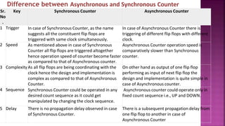
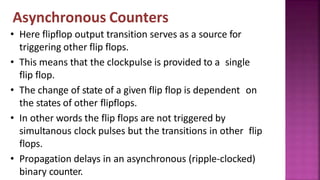
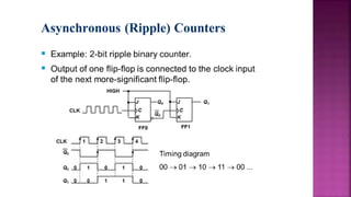
2. There are two main types of counters: asynchronous/ripple counters where each flip-flop is triggered by the previous one, and synchronous counters where all flip-flops are triggered simultaneously by a clock. Asynchronous counters are simpler but slower while synchronous counters are faster but more complex.
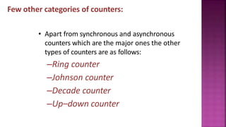
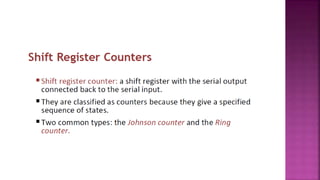
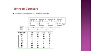
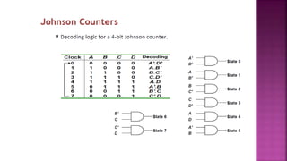
3. Binary counters follow a binary sequence and can count from 0 to 2n-1 for an n-bit counter. Other counter types include up/down, ring, Johnson, and decade counters.