Downloaded 501 times


![Voltage ratio test
To measure the voltage ratio
of one winding to another
associated with a lower or
equal voltage.
Accepted criteria
% Ratio Error : ± 0.5 % of declared
ratio on all taps
Phase Angle error: 0.5% radian
% Ratio error (Deviation) =
[(measured ratio – calculated ratio) /
calculated ratio] x 100
Calculated voltage ratio = HV
winding voltage / LV winding voltage
38](https://image.slidesharecdn.com/0bb05ffe-017d-49c7-a675-dee8ed90fa15-151026170536-lva1-app6891/85/Presentation_Power_Transformers-1-38-320.jpg)


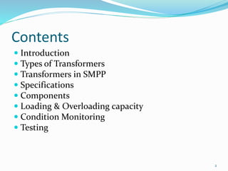
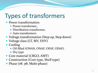
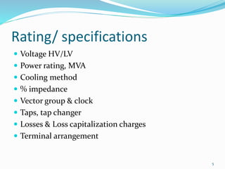
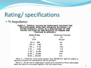
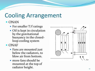
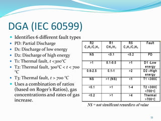
This document provides an overview of power transformers, including: 1. It describes different types of transformers such as power, distribution, auto, step-up, step-down transformers and discusses their various components and specifications. 2. It explains transformers used in power plants along with their ratings, cooling methods, impedance and other details. 3. It covers transformer components, testing procedures, loading capacity, condition monitoring techniques and diagnostic tests to evaluate transformer performance and health.


![Transformer Repair Workshop Report [EEE]](https://cdn.slidesharecdn.com/ss_thumbnails/transformerrepairworkshopeee-140621072318-phpapp01-thumbnail.jpg?width=640&height=640&fit=bounds)