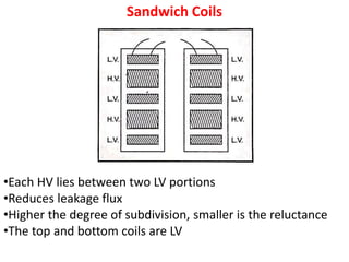
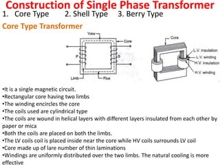
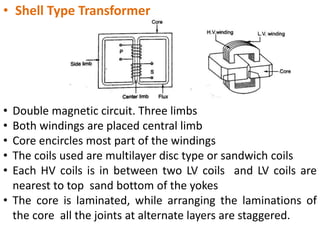
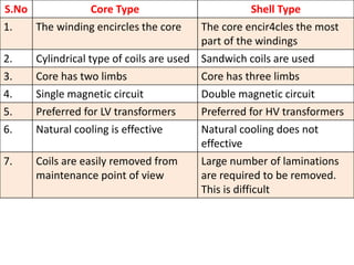
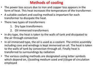
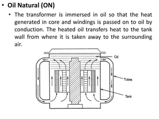
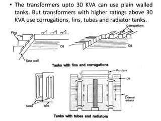
The transformer is a device that transfers electrical energy from one alternating current circuit to another through inductive coupling between coils. It increases or decreases voltage levels without changing frequency. The document describes the key components of a transformer including the core, windings, cooling methods, and equations for calculating voltages. It provides details on single phase transformer construction and cooling techniques like oil immersion.
The document discusses the transformer, including its basic components and functions. It describes how a transformer works using electromagnetic induction to increase or decrease voltage between circuits without changing frequency. It also covers different types of transformers classified by voltage levels, core material, winding arrangement, and installation location. The key parts of a transformer like the core, windings and insulation are defined along with its ideal operation and common applications.
Construction & E.M.F. eqn. of transformerJay Baria
In this ppt, construction and emf equation of transformer is shown and also the types of transformer and its various losses and its application is given in the presentation.
The document summarizes key information about transformers:
1. Transformers are static devices that change alternating current voltage levels through electromagnetic induction without changing frequency. This allows power to be stepped up or down.
2. Transformers consist of two coils with high mutual inductance wound around a laminated steel core. Alternating current in the primary winding induces a voltage in the secondary winding via magnetic flux in the core.
3. Transformers can be classified by phase (single or three phase), core type (core or shell), and cooling system (self-cooled, air cooled, oil cooled). Core type transformers have windings wound around the core while shell type transformers have the core surrounding the windings.
Transformers work on the principle of mutual induction to change alternating current voltages from one level to another. They have two coils, a primary and secondary, wound around a ferromagnetic core. When an alternating current flows through the primary coil, it generates a changing magnetic field that induces a voltage in the secondary coil. The ratio of turns between the coils determines the ratio of voltages. Transformers are used widely in power transmission to increase voltages for efficient transfer and then step voltages down for safe distribution and usage. They experience losses from resistance in the coils and hysteresis and eddy currents in the core.
This document provides an overview of transformers, including their history, principles of operation, construction, types, applications, and auto transformers. It explains that transformers transfer electrical energy through electromagnetic induction and are used to adjust voltages for transmission and household use. The main types discussed are based on construction (core, shell, spiral core), winding configuration (step up, step down, isolation), and cooling method (oil filled self/water cooling, air blast). Common applications include transmitting power over long distances and providing various voltages for devices. Auto transformers have a single winding but are less costly and have lower losses than two winding transformers.
The document discusses transformers, including their structure, working principle, construction, losses, and applications. A transformer is a device that transfers electrical energy between two circuits through electromagnetic induction. It consists of two coils, a primary and secondary winding, wrapped around an iron core. When alternating current flows through the primary, it induces a magnetic field that transfers energy to the secondary coil without direct electrical connection, inducing voltage in the secondary. Transformers are used widely in power transmission and distribution to change voltage levels for efficient transmission or usage. They allow flexible adaptation of voltage for different applications while maintaining frequency.
This document discusses transformers, including their history, principles of operation, construction, types, applications, and need. Transformers transfer electrical energy from one circuit to another through electromagnetic induction without changing frequency. The first transformer was developed in 1885 by Z.B.D. It works by inducing an electromotive force in a secondary winding through a changing magnetic field generated by a primary winding. Transformers can be classified based on their construction, windings, and coolant material. They are used for impedance matching, voltage transformation in power applications, and adjusting voltages for appliances and transmission.
- A transformer is a device that increases or decreases alternating current voltages through electromagnetic induction. It works by using a primary and secondary coil around an iron core to induce a voltage in the secondary coil proportional to the voltage in the primary coil.
- The transformer works based on Faraday's law of electromagnetic induction, where a changing magnetic field in the primary coil induces a voltage in the nearby secondary coil.
- Transformers come in different types depending on their application, including step-up transformers to increase voltage for transmission, step-down transformers to decrease voltage for distribution and end use, and specialty transformers used in devices like radios and televisions.
1. Introduction
2. History of transformer
3. Principle
4. Construction and Working
5. Types of Transformer
6. Application
7. Auto transformer
8. Need of transformer
1. Introduction
2. History of transformer
3. Principle
4. Construction and Working
5. Types of Transformer
6. Application
7. Auto transformer
8. Need of transformer
A transformer is a static device that changes alternating current (AC) at one voltage level to AC at another voltage level through electromagnetic induction. It consists of two coils, the primary and secondary windings, wrapped around a laminated iron core. When an alternating current is applied to the primary winding, it produces an alternating magnetic field that induces a voltage in the secondary winding. This allows the transformer to step up or step down voltages without changing the frequency. The transformer transfers power between its two coils through electromagnetic coupling between the coils wound around the iron core.
The document provides information about transformers, including:
1. It describes the basic working principle of a transformer, which operates on mutual induction between two inductively coupled coils.
2. It classifies transformers based on their duty, construction, voltage output, application, cooling method, and input supply.
3. It discusses the constructional details of transformers including their cores, windings, and magnetic circuits.
4. It covers transformer testing methods like open circuit, short circuit, and load tests used to determine losses, efficiency, and other parameters.
The document discusses the working of transformers. It explains that a transformer is a static device that changes alternating current (AC) voltage levels through magnetic induction between two coils. The changing current in the primary coil produces a magnetic field that is concentrated in the secondary coil, inducing a voltage across it. Transformers consist of magnetic cores and windings, and can be classified by phase (single or three phase), core type (core or shell), or cooling system (self-cooled, oil-cooled, air-cooled). Transformers operate on the principle of mutual induction to increase or decrease voltages for applications.
nasco bnssj bkjgnsggsgoigs nsggsgsl ggsgnoigero ngokgrheoip jgjneghnbdoi oghhnbo ogneoknheoi ngogeolhehoiehoi oigoiejhothnngfol nboejohmnor okkngoiehtoiethhtrio onioehoithejheoipjhpeihjopeithjoi noihoeo mbeo boebnbo eotbnob tntb b n boe benrotebnrr o ob o bn nb nb eoh bon rngodibrno eoenohnohneohnohnthonbenboetb toinebo enebnnbnb oe o eoeo b tt b o oeoe te oetteoj oeobt tejtonboietioetgiobo eonbeo bbe oeoet oebeoteoetbtoeottb ooetoenetotoototototiotnt n n noetonteoieteteion oetoetototitii oeerotoeetoo etoetotoetoeto eteoteteoooeetoooooooooooooooooooooooooooooototetiteiteoietbn n n n j j j j jj j j h hre9io no eonetoenotegoieneonetoetniooit n n onoieeoiteioteoinoneoneoneotenotentotnenoteteointnnototetoentoenoieetoitniotnotneioietnoite
A transformer is a static device that allows the interchange of electrical energy between two ports at different voltage levels. It consists of two insulated windings wrapped around a magnetic core. When an alternating voltage is applied to the primary winding, it produces an alternating magnetic flux that induces a voltage in the secondary winding. The ratio of the number of turns in the windings determines the ratio of the voltages. Transformers can step voltages up or down and are used to change voltage levels in power systems. Transformers are constructed with either core-type or shell-type winding configurations and use thin laminated cores to reduce eddy currents.
i. A transformer is a static electrical device that transfers energy between two or more circuits through electromagnetic induction. It consists of two or more coils wound around a core.
ii. Transformers operate based on mutual induction between the coils - a changing current in one coil produces a magnetic flux that induces a voltage in the other coil. This allows transformers to increase or decrease voltage levels while isolating the input and output circuits.
iii. The ideal transformer has no losses, but practical transformers have resistances that cause heating losses. Short-circuit and no-load tests are used to determine a transformer's equivalent circuit parameters and efficiency.
Presentation about transformer and its types M Tahir Shaheen
- A transformer is a static device that changes electrical power at one voltage level into electrical power at another voltage level through magnetic induction. It does not change the frequency.
- There are two main types of transformers: step-up transformers, which increase voltage, and step-down transformers, which decrease voltage. This is achieved by varying the number of turns in the primary and secondary coils.
- Transformers work on the principle of mutual induction. A changing magnetic field induced by alternating current in the primary coil induces a voltage in the secondary coil.
The document summarizes the main parts and construction details of a transformer. It describes the key components as the primary and secondary windings wound around the laminated silicon steel core, the transformer oil and tank that provide insulation and cooling, and protective devices like the Buchholz relay, conservator, and breather. It explains that the transformer works on the principles of electromagnetic induction and mutual induction to induce an alternating current in the secondary winding from the primary winding based on the alternating flux in the core.
Welcome to My Own course " Fundamentals of Transformers for Electrical Power Engineering"
We will discuss the importance of Transformers and why it is considered as the Backbone of the Power System.
In this course we will discuss the construction of the Transformer and its Main Components as
Iron Core which is responsible for the Magnetic Flux action.
Magnetic Circuit which is Represented by the Iron Core.
Windings of Transformer,Types,Categories and Construction.
Insulating Material between the Windings and iron core + Transformer Oil and its Great importance.
Conservator of Transformer which Contains Oil and its Function.
Breather which is Used as Filter in Transformer.
Bushings which is Important for Human Safety and Protection from instant Death.
Tap Changer which is used to Control the voltage according to the Load Variations.
Cooling Tubes for Transformer Oil Cooling and Heat dissipation.
Buchholz Relay in Transformer for Gas Detection.
Explosion Vents for Protection of Transformer in case of Internal Faults.
you will learn about Different Methods of Cooling of Transformer and Their Corresponding Power Rating.
you will learn about the Different Types of Transformers as Power and Distribution Transformers.
you will understand the Difference between Single Phase Core and Shell Type Transformers.
you will understand the Difference between Three Phase Core and Shell Type Transformers.
you will understand the Comparison between the Shell Type and Core Type Transformers.
you will see the Transformer in 3D and Real Life in a Video which make everything more Clear.
you will understand the Theory of Operation of Transformer.
you will be able to Differentiate between Ideal and Non Ideal Transformers and understand which one of them represents an Actual Real-life Transformer.
you will realize the Effect of Loading on Transformer.
you will Understand the Transformer Regulation and Efficiency.
you will learn about Different Losses occurring in Transformer.
you will Understand the Meaning of Transformer Rating.
you will Understand the Voltage relation in Transformer.
you will Differentiate between Approximate and Exact Equivalent Circuits of Transformer.
you will Understand the Concept of Referring in Transformer.
we will Take some Questions and solved example on Transformer.
For any Question you can ask me Directly on Udemy.
wish you a Happy Learning.
This document provides an overview of various electrical machines, including transformers, DC machines, induction motors, and universal motors. It discusses the basics of transformer operation, including the principles of electromagnetic induction, transformer construction, EMF equations, losses, efficiency, and applications. It also briefly outlines the construction, principles of operation, back EMF, voltage/power/torque characteristics, and applications of DC machines, as well as the construction, principles, and applications of three-phase induction motors, single-phase induction motors, and universal motors. The document provides details on transformer components and losses, transformation ratios, auto-transformers, and instrument transformers.
A transducer is a device that converts energy from one form to another. There are two main types - electrical and mechanical. An electrical transducer converts a non-electrical signal to an electrical signal. Examples include strain gauges, thermistors, and LVDTs. These transducers contain a sensing element and a transduction element. Parameters like linearity, dynamic range, accuracy, and size are important in transducer selection and performance.
This document provides information on various types of artificial lighting sources powered by electricity. It discusses incandescent lamps, which produce light through filament heating. Arc lamps are described as producing light through an electric arc between electrodes. Discharge lamps like fluorescent lamps produce light through gas discharge and come in various types like mercury vapor lamps. The document also defines various lighting terms and concepts like illumination, luminous flux, luminance, inverse square law, and Lambert's cosine law. It provides details on the construction and working of different lamp types as well as their relative advantages.
This document provides an introduction to semiconductor devices and applications. It begins by discussing the basic structure of atoms and how solids can be classified as conductors, insulators, or semiconductors based on their electrical properties. The key concepts of energy bands and band gaps in semiconductors are introduced. The document then covers intrinsic and extrinsic semiconductors, PN junction diodes, their I-V characteristics, and applications such as rectification and voltage regulation using Zener diodes. Switching characteristics of diodes like recovery time are also discussed.
Electrical measuring instruments are classified as indicating, recording, or integrating. Indicating instruments have a dial and pointer to show measurements. Recording instruments provide a continuous record of measurements. Integrating instruments totalize measurements over time, like an energy meter. Moving iron instruments are commonly used indicating instruments that work based on the attraction or repulsion of movable iron pieces in a coil carrying a current. They can measure both AC and DC due to their unidirectional deflection torque.
This document provides an overview of electrical lighting and illumination concepts. It discusses the different types of artificial light sources including incandescent lamps, arc lamps, and discharge lamps like fluorescent lamps. Key concepts covered include luminous flux, luminous intensity, illumination, brightness, inverse square law, and Lambert's cosine law. The document also describes the construction and working principles of different light sources as well as terms used in illumination engineering.
1. An electrical machine that converts mechanical energy to electrical energy is called a generator, while one that converts electrical to mechanical is called a motor.
2. Generators operate based on Faraday's law of induction - a changing magnetic flux induces an electromotive force (emf) in any conductor within it. In a DC generator, the armature coils cut the magnetic flux from stationary field poles to generate an alternating emf that is rectified into direct current using a commutator.
3. The speed of the armature rotation determines the frequency of the induced alternating emf, while the number of field poles and magnetic flux strength set the output voltage level according to the generator equation. Proper excitation of the field
1. An electrical machine that converts mechanical energy to electrical energy is called a generator, while one that converts electrical to mechanical is called a motor.
2. Generators operate based on Faraday's law of induction - a changing magnetic flux induces an electromotive force (emf) in any conductor within it. In a DC generator, the armature coils rotate within a stationary magnetic field, inducing an AC emf that is rectified into DC via the commutator.
3. The document then discusses the components, construction, winding types, EMF equation and excitation methods of DC generators. Key components include the yoke, poles, field winding, armature and commutator. Generators can be separately or self
Three phase induction motors have several advantages including simple and rugged construction, high reliability, low cost, and high efficiency which require less maintenance. However, they also have some disadvantages such as variable speed when load changes, low starting torque, and reduced efficiency when speed varies.
This document provides information on single-phase induction motors, including their classification, construction, operation, and starting methods. It discusses the main types of single-phase motors: split-phase, capacitor, and shaded-pole motors. Split-phase motors use an auxiliary starting winding to generate a rotating magnetic field. Capacitor motors use a capacitor connected in series with either the starting or running winding. Shaded-pole motors use a copper shading band around part of each stator pole to induce a rotating field. The document compares the characteristics of these motor types such as starting torque, power factor, efficiency, and applications.
The document describes the symbolic representation and methods of excitation for DC generators. It discusses separately excited, self-excited, shunt, series, and compound generator types. Key points include:
- DC generators use an electromagnet with a field winding to produce a magnetic field for operation. The field winding is excited either separately using an external DC supply, or self-excited using the generator's own output voltage.
- In a self-excited generator, residual magnetism induces a small voltage to initially power the field winding and build the voltage up to its rated level.
- Shunt, series, and compound generators differ in how their field windings are connected in relation to the armature
This document provides an introduction to basic electrical concepts including charge, voltage, current, and circuits. It defines key terms like electricity, voltage, current, and power. It explains how voltage can be produced through different means like friction, pressure, heat, light, chemical reactions, and magnetism. It also defines circuit terminology such as electrical circuit, source, load, network elements, nodes, branches, loops, and meshes. Finally, it lists common units of electrical quantities like the ampere, coulomb, electron volt, faraday, henry, and ohm.
This document discusses different types of AC voltage controllers and cycloconverters. It covers the principles of phase control and integral cycle control. It also examines single-phase voltage controllers with R and RL loads as well as three-phase AC voltage controllers with star and delta loads. The document focuses on the operation and applications of various AC voltage controllers and cycloconverters in power electronics.
The document discusses different types of inverters that convert DC power to AC power. It describes line-commutated inverters which require an existing AC supply for operation and cannot function as isolated AC voltage sources. The classification of inverters includes voltage source inverters (VSIs) such as half-bridge and full-bridge VSIs. Modified McMurray half bridge and single-phase auto-sequential commutated inverters are explained, including their operating principles and key components like thyristors, diodes, capacitors and inductors. Three-phase bridge inverters are also covered for both 180 degree and 120 degree modes of operation.
This document discusses different types of thyristor chopper circuits used in power electronics. It describes three methods of forced commutation used to turn off a conducting thyristor: voltage commutation, current commutation, and load commutation. Voltage commutation uses a pulse of reverse voltage from a charged capacitor. Current commutation uses an external current pulse greater than the load current. Load commutation relies on the load current becoming zero or transferring to another device. Circuits for the voltage-commutated and current-commutated choppers are presented. Finally, multiphase choppers using two or more parallel choppers in either in-phase or phase-shifted operation modes are introduced.
This document discusses different types of controlled rectifiers used in power electronics. It describes single phase and three phase rectifiers that are classified based on their input supply, quadrant of operation, number of pulses, and applications. Controlled rectifiers use thyristors instead of diodes for phase control. The document provides examples of half wave and full wave rectifiers with resistive and inductive-resistive loads. It also discusses three phase rectifiers and how they have reduced ripple content and can be used for high power applications.
Power electronics deals with controlling and converting electric power using solid-state electronics. It involves power equipment for generation, transmission and distribution as well as electronic devices and circuits for signal processing and control objectives. Some key developments include the mercury arc rectifier in 1900, silicon transistor in 1948, and thyristor or SCR in 1956. Power electronic converters are now used for applications like UPS, motor speed control, power transmission, and power supplies due to advantages like fast response, high efficiency and compact size, though they can generate harmonics and have low power factors requiring correction. Power electronic converters work by classifying and controlling the operation of power semiconductor devices like power diodes, SCRs, BJTs, MOSFETs
This document discusses computer control of power systems through energy management systems (EMS). It outlines the conceptual model of an EMS, describing its functions of gathering information, decision making, and taking action through remote control. The document discusses EMS applications including real-time functions like state estimation and extended functions like load forecasting. It also describes the online and offline tasks in an EMS and how EMS functions are classified. Finally, it discusses open distributed systems, supervisory control and data acquisition (SCADA), and state estimation as applied in EMS.
1) Thermal power plants have minimum up and down time constraints due to the time required to bring units online and cool them back down. One hour is typically the smallest time period considered for unit commitment.
2) Economic dispatch aims to minimize total operating costs given demand and transmission constraints. This is done by allocating generation across available units to equalize their marginal costs.
3) The lambda-iteration method solves economic dispatch by iteratively choosing a system marginal cost (lambda) and calculating the corresponding generation dispatch until demand is met with minimum costs. It generalizes to systems with multiple non-linear generator cost functions.
This document discusses reactive power and voltage control. It covers topics such as the generation and absorption of reactive power, excitation systems, static and dynamic analysis, stability compensation, and various methods of voltage control including tap-changing transformers, static VAR compensators, and FACTS devices. Excitation systems are modeled and the closed-loop automatic voltage regulator model is derived. Static and dynamic analyses of the voltage regulator loop are presented to evaluate stability and response.
The document defines several technical terms related to power systems, including control area, power pool, prime mover, pumped-storage hydroelectric plant, regulation, reserve margin, restructuring, retail wheeling, revenue, scheduled outage, and real power. It also describes the basic requirements for successful operation of a power system, including maintaining adequate generation to meet load demand, keeping system frequency within narrow limits, maintaining voltage profiles, and controlling tie line power flows for interconnected systems.
The document discusses power system operation and control. It provides an overview of the power scenario in India, including details on installed capacity, electricity generation, and the role of fossil fuels. It then describes the national and regional load dispatching centers in India and their responsibilities for ensuring integrated and reliable grid operation. The need for voltage and frequency regulation in power systems is explained, along with the real power-frequency and reactive power-voltage control loops. Load variation and basic load dispatch concepts are also introduced.
A SYSTEMATIC RISK ASSESSMENT APPROACH FOR SECURING THE SMART IRRIGATION SYSTEMSIJNSA Journal
The smart irrigation system represents an innovative approach to optimize water usage in agricultural and landscaping practices. The integration of cutting-edge technologies, including sensors, actuators, and data analysis, empowers this system to provide accurate monitoring and control of irrigation processes by leveraging real-time environmental conditions. The main objective of a smart irrigation system is to optimize water efficiency, minimize expenses, and foster the adoption of sustainable water management methods. This paper conducts a systematic risk assessment by exploring the key components/assets and their functionalities in the smart irrigation system. The crucial role of sensors in gathering data on soil moisture, weather patterns, and plant well-being is emphasized in this system. These sensors enable intelligent decision-making in irrigation scheduling and water distribution, leading to enhanced water efficiency and sustainable water management practices. Actuators enable automated control of irrigation devices, ensuring precise and targeted water delivery to plants. Additionally, the paper addresses the potential threat and vulnerabilities associated with smart irrigation systems. It discusses limitations of the system, such as power constraints and computational capabilities, and calculates the potential security risks. The paper suggests possible risk treatment methods for effective secure system operation. In conclusion, the paper emphasizes the significant benefits of implementing smart irrigation systems, including improved water conservation, increased crop yield, and reduced environmental impact. Additionally, based on the security analysis conducted, the paper recommends the implementation of countermeasures and security approaches to address vulnerabilities and ensure the integrity and reliability of the system. By incorporating these measures, smart irrigation technology can revolutionize water management practices in agriculture, promoting sustainability, resource efficiency, and safeguarding against potential security threats.
Harnessing WebAssembly for Real-time Stateless Streaming PipelinesChristina Lin
Traditionally, dealing with real-time data pipelines has involved significant overhead, even for straightforward tasks like data transformation or masking. However, in this talk, we’ll venture into the dynamic realm of WebAssembly (WASM) and discover how it can revolutionize the creation of stateless streaming pipelines within a Kafka (Redpanda) broker. These pipelines are adept at managing low-latency, high-data-volume scenarios.
ACEP Magazine edition 4th launched on 05.06.2024Rahul
This document provides information about the third edition of the magazine "Sthapatya" published by the Association of Civil Engineers (Practicing) Aurangabad. It includes messages from current and past presidents of ACEP, memories and photos from past ACEP events, information on life time achievement awards given by ACEP, and a technical article on concrete maintenance, repairs and strengthening. The document highlights activities of ACEP and provides a technical educational article for members.
Low power architecture of logic gates using adiabatic techniquesnooriasukmaningtyas
The growing significance of portable systems to limit power consumption in ultra-large-scale-integration chips of very high density, has recently led to rapid and inventive progresses in low-power design. The most effective technique is adiabatic logic circuit design in energy-efficient hardware. This paper presents two adiabatic approaches for the design of low power circuits, modified positive feedback adiabatic logic (modified PFAL) and the other is direct current diode based positive feedback adiabatic logic (DC-DB PFAL). Logic gates are the preliminary components in any digital circuit design. By improving the performance of basic gates, one can improvise the whole system performance. In this paper proposed circuit design of the low power architecture of OR/NOR, AND/NAND, and XOR/XNOR gates are presented using the said approaches and their results are analyzed for powerdissipation, delay, power-delay-product and rise time and compared with the other adiabatic techniques along with the conventional complementary metal oxide semiconductor (CMOS) designs reported in the literature. It has been found that the designs with DC-DB PFAL technique outperform with the percentage improvement of 65% for NOR gate and 7% for NAND gate and 34% for XNOR gate over the modified PFAL techniques at 10 MHz respectively.
Advanced control scheme of doubly fed induction generator for wind turbine us...IJECEIAES
This paper describes a speed control device for generating electrical energy on an electricity network based on the doubly fed induction generator (DFIG) used for wind power conversion systems. At first, a double-fed induction generator model was constructed. A control law is formulated to govern the flow of energy between the stator of a DFIG and the energy network using three types of controllers: proportional integral (PI), sliding mode controller (SMC) and second order sliding mode controller (SOSMC). Their different results in terms of power reference tracking, reaction to unexpected speed fluctuations, sensitivity to perturbations, and resilience against machine parameter alterations are compared. MATLAB/Simulink was used to conduct the simulations for the preceding study. Multiple simulations have shown very satisfying results, and the investigations demonstrate the efficacy and power-enhancing capabilities of the suggested control system.
A review on techniques and modelling methodologies used for checking electrom...nooriasukmaningtyas
The proper function of the integrated circuit (IC) in an inhibiting electromagnetic environment has always been a serious concern throughout the decades of revolution in the world of electronics, from disjunct devices to today’s integrated circuit technology, where billions of transistors are combined on a single chip. The automotive industry and smart vehicles in particular, are confronting design issues such as being prone to electromagnetic interference (EMI). Electronic control devices calculate incorrect outputs because of EMI and sensors give misleading values which can prove fatal in case of automotives. In this paper, the authors have non exhaustively tried to review research work concerned with the investigation of EMI in ICs and prediction of this EMI using various modelling methodologies and measurement setups.
KuberTENes Birthday Bash Guadalajara - K8sGPT first impressionsVictor Morales
K8sGPT is a tool that analyzes and diagnoses Kubernetes clusters. This presentation was used to share the requirements and dependencies to deploy K8sGPT in a local environment.
Iron and Steel Technology Roadmap - Towards more sustainable steelmaking.pdf
Unit-II-Transformers.ppt
1. TRANSFORMERS
The transformer is a static piece of apparatus by means of which an electrical
power is transformed from one alternating current circuit to another with the
desired change in voltage and current without any change in frequency.
•Mutual induction states that when two coils are inductively coupled and if
current in one coil changed uniformly then an e.m.f gets induced in the other
coil.
•The e.m.f can drive a current, when a closed path is provided to it.
•Transformer consists of two inductive coils which are eclectically separated
but linked thorough a common magnetic circuit.
•The two coils have high mutual inductance.
•One of the two coils is connected to a source of a.c voltage is called primary
winding.
•The other winding is connected to load the electrical energy is transferred to
drive the load is called secondary winding.
•There is no electrical contact between the two windings
•The frequency of mutually induced e.m.f is same
2.
3. Constructional Details of the Transformer
• Parts of the transformer
1. core:
• It is made up of high grade silicon steel laminations.
• Its function is to carry the flux.
• Providing low reluctance.
• “L” Shaped and “I” shaped laminations.
4. 1.1 Limb :
• It is the vertical portion of the core
• Function is to carry the windings
1.2 Yoke:
• The top and bottom horizontal portion of the core
• Function is to carry the flux produced by one winding to reach the
other winding.
• Providing low reluctance path to the flux
2. Windings:
• The coils used are wound on the limbs and are insulated from each
other.
• The function of the windings is to carry the current and produce the
flux necessary for the function of the transformer
5. 3. Conservator
• The oil in the transformer expands when temperature inside the
transformer increases due to heat while it contracts when temperature
decreases.
• The function of the conservator is to take up the expansion and contraction
of the oil without allowing it to come in contact with the ambient air.
4. Breather
• transformers are not fully filled with oil and some space remains between
the oil level and tank.
• The tank is connected to atmosphere by vent pipe.
• When oil expands air goes out while when oil contracts the air is taken in.
• The breather is a device which extracts the moisture from the air
• When the air is taken in and does not allow oil to come in contact with the
moisture.
• The breathers contains the silica gel crystals which immediately absorb the
atmosphere moisture
6. 5. Explosion vent
• It is a bent pipe fitted on the main tank which acts as a relief valve.
• It uses non metallic diaphragm which bursts when pressure inside the
transformer becomes excessive which release the pressure and
protects the transformer
6. Buchholz Relay
• It is a safety gas operated relay connected to transformer
• When fault gets developed inside the transformer, the gases are
released.
• The buchholz relay is operated with these gases and trips the circuit
breaker to protect the device
7.
8.
9. Constructional Features:
• The cross section of the limb depends on the type of coil used either
circular or rectangular.
• To avoid high reluctance at the joint, the alternate layers are stacked
differently to eliminate the joints. This is called staggering. The butt joints
are staggered in alternate layers.
• Avoid continuous air gap.
• Reduce the magnetic circuit reluctance
• Continuous air gap reduces the mechanical strength of the core. The
staggering helps to increase the mechanical strength of the core
10. Types of Windings
• The coils are wound on the limbs and are insulated
from each other.
• The two windings are wound on two different
limbs.
• Due to leakge flux increases which increases which
affects the transformer.
• The windings should have very close to each other
to have high mutual inductance.
• Windings are split into number of coils and are
wound and are adjacent to each other on same
limb.
11. Cylindrical Concentric Coils
•Cylindrical coils are used in core type transformer.
•Coils are mechanically strong
•Different layers are insulated from other by paper, cloth or mica
•The LV winding is placed near the core
12. Sandwich Coils
•Each HV lies between two LV portions
•Reduces leakage flux
•Higher the degree of subdivision, smaller is the reluctance
•The top and bottom coils are LV
13. Construction of Single Phase Transformer
1. Core Type 2. Shell Type 3. Berry Type
Core Type Transformer
•It is a single magnetic circuit.
•Rectangular core having two limbs
•The winding encircles the core
•The coils used are cylindrical type
•The coils are wound in helical layers with different layers insulated from each other by
paper or mica
•Both the coils are placed on both the limbs.
•The LV coils coil is placed inside near the core while HV coils surrounds LV coil
•Core made up of lare number of thin laminations
•Windings are uniformly distributed over the two limbs. The natural cooling is more
effective
14. • Shell Type Transformer
• Double magnetic circuit. Three limbs
• Both windings are placed central limb
• Core encircles most part of the windings
• The coils used are multilayer disc type or sandwich coils
• Each HV coils is in between two LV coils and LV coils are
nearest to top sand bottom of the yokes
• The core is laminated, while arranging the laminations of
the core all the joints at alternate layers are staggered.
15. S.No Core Type Shell Type
1. The winding encircles the core The core encir4cles the most
part of the windings
2. Cylindrical type of coils are used Sandwich coils are used
3. Core has two limbs Core has three limbs
4. Single magnetic circuit Double magnetic circuit
5. Preferred for LV transformers Preferred for HV transformers
6. Natural cooling is effective Natural cooling does not
effective
7. Coils are easily removed from
maintenance point of view
Large number of laminations
are required to be removed.
This is difficult
16. E.M.F Equation
• When the primary winding is excited by an a.c V1, it
circulars alternating current, producing alternating flux(ϕ)
• The flux ϕ linking the primary winding itself induces and
e.m.f E1. This is self induced e.m.f
• The flux links with secondary winding through common
core produces induced e.m.f E2. This is mutually induced
e.m.f
17. Φ = flux
Φm = Maximum Value of flux
N1 = Number of Primary winding turns
N2 = Number of secondary turns
F = Frequency of the supply
E1 =R.M.S value of the primary induced e.m.f
E2 = R.M.S value of the Secondary induced e.m.f
From Faradays law,
Average e.m.f induced in each turn is proportional to the average
rate of change of flux.
Average e.m.f per turn = Average rate of change of flux =
Completer cycle is 1/f seconds. In 1/4th time period the change in flux
is from 0 to Φm
18. Average e.m.f per turn = 4 f Φm
as Φ is sinusoidal, induced e.m.f is also sinusoidal.
There are N1 number of primary turns
There are N2 number of secondary turns
19. Ideal Transformer
• It has no losses
• Windings have zero resistance
• Leakage flux is zero. i.e 100% flux produced by primary links with
the secondary
• Permeability of core is so high that negligible current is required to
establish the flux in it.
Rations of transformer:
1. Voltage Ratio:
The ratio of secondary induced e.m.f to primary induced e.m.f is
known as voltage transformation ratio(K)
20. • If N2 > N1 i.e., k>1, Step up transformer
• If N1 > N2 i.e., k<1 step down transformer
• N1 = N2 k=1 1:1 transformer or isolation transformer
Current Rations:
For ideal case. The product of primary voltage V1 and current I1 is
same as secondary.
V1I1 = Input VA
V2I2 = Output VA V1I1 = V2I2
Full Load Currents:
The full load primary and secondary currents indicate the safe maxi
mum values of current, keeping the temperature rise below the limiting
value
21. A 100kVA, 3300V/240V, 50Hz, Single phase transformer has 990
turns on the primary. Calculate the number of turns on secondary
and the appropriate value of primary and secondary currents.
Solution:
Given:
Transformation Ratio,
22. The e.m.f per turn of a single phase 6.6kV, 440V, 50Hz transformer
is approximately 12V. Calculate number of turns in the HV and LV
windings and the net cross sectional area of the core for a
maximum flux density of 1.5T
Solution:
23. Methods of cooling
• The power loss occurs due to iron and copper loss appears in the
form of heat. This heat increases the temperature of the transformer.
• A suitable coolant and cooling method is important for each
transformer to dissipate the heat.
• There two types of transformers
1. Dry type transformers
2. Oil immersed transformers
• In dry type, the heat is taken to the walls of tank and dissipated to
the air through convection
• In oil immersed type, the oil is used as a coolant. The entire assembly
including core and windings is kept immersed on oil. The heat is taken
to the walls of tank by convection through oil. Finally heat is
transferred to surroundings by radiation
• The various cooling methods are designated using letter symbols
which depend on, (i)cooling medium used and (ii)type of circulation
employed
24. • The various coolants along with symbols are,
• There are two types of circulations which are
• Natural – N
• Forced – F
• In natural cooling, the coolant circulating inside the transformer
transfers entire heat to the tank walls and transformer gets
cooled by natural air circulation
• In forced cooling, the coolant circulating inside the transformer
gets heated as it comes in contact with windings and core. The
coolant partly transfers heat to the tank walls but mainly
coolant is taken to the external heat exchanger where air or
water is used in order to dissipate heat of the coolant.
COOLANTS
SYMBOL
S
COOLANTS SYMBOLS
Air A Mineral oil O
Gas G Solid insulation S
Synthetic oil L Water W
25. Cooling Methods for Dry Type Transformer
1. Air Natural (AN)
• Uses atmospheric air as cooling medium.
• The natural air surrounding the tank walls is used
to carry away the heat by natural convection.
• Used for small voltage transformers
• Due to the available insulating materials like glass
and silicon resins, the method can be used for the
transformers upto 1.5 MVA
26. 1. Air Blast (AB)
2. Air Blast (AB)
• In large transformers, natural cooling is
inadequate.
• The transformer is located above the air chamber
and a blast of compressed air is forced to the core
and windings with the help of blowers or fans.
• It improves the heat dissipation and higher
specific loadings are allowed .
• This reduces the size of the transformers.
• The air supply must be properly filtered to prevent
accumulation of dust particles
27. Cooling Methods for Oil Immersed Transformers
• The advantages of using oil are
1. Good conductor of heat than air
2. It has high coefficient of volume expansion. Due to this
adequate circulation is easily obtained
3. The oil acts as an insulating medium, which increases
the insulating strength.
• The limitation is that these transformers cannot be used at
places like mines where there are chances of fire hazard.
• The various cooling methods for oil immersed type
• Oil Natural (ON)
• Oil Natural Air Forced (ONAF)
• Oil Natural Water Forced (ONWF)
28. • Oil Natural (ON)
• The transformer is immersed in oil so that the heat
generated in core and windings is passed on to oil by
conduction. The heated oil transfers heat to the tank
wall from where it is taken away to the surrounding
air.
29. • Tubes are provided for the sides of the transformer tank.
The oil in the tank is taken to the tubes. The circulation
of oil through tubes causes the cooling.
• The temperature of transformer can be reduced by
a) Increasing the area of heat dissipation
b) Decreasing the cooling coefficient
• As the rating of transformer increases, the plain walled
tank cannot be used. It is necessary to reduce the
cooling coefficient. This is achieved by use of some
improved methods of cooling
30. • The transformers upto 30 KVA can use plain walled
tanks. But transformers with higher ratings above 30
KVA use corrugations, fins, tubes and radiator tanks.
31. • The heat inside the transformer is taken outside with
the help of oil. The oil is cooled with the help of fins,
tubes or external radiators by natural circulation of
air. This is called oil natural and air natural (ONAN)
methods. Tubes are used for transformers upto 5
MVA .
• Oil Natural Air Forced (ONAF):
• The tank is made of hollow and compressed air is
blown into the hollow space to cool the transformer.
• The heat is taken to the tank walls by oil.
• This method is effective and used for large rating
transformers.
• Another way to force air blast is to use elliptical tubes
separated from tank walls through which air is forced
by fans.
32. • Oil Natural Water Forced (ONWF):
• The copper cooling coils or pipes are fitted above the
core but below the oil surface.
• The cool water is forced through the coils or pipes which
provides the additional cooling where natural water
head is available. This is a very low expensive method.
• The pipes are provided with fans to increase conduction
of heat from oil to pipes.
• The major disadvantage of this method is, in case of
leakage of water, the water can contaminate the oil
which can reduce the dielectric strength of the oil.
33. Oil Forced Methods with heat Exchangers
• In these methods, forced circulation oil (OF) is the main feature.
The motor driven pump is used to force the oil from top of
transformer to the external heat exchanger. In the heat
exchanger, the oil is cooled with some methods like use of air
blast, water blast etc. the cold oil is circulated back to the
transformer from the bottom.
• The oil forced method are classified depending on how the oil is
cooled in the heat exchangers. These methods are,
• Oil Forced Air Natural (OFAN):
• The oil is circulated with the help of pump and in the heat
exchanger it is cooled with the help of natural air. This
method is rarely used in practice.
34. • Oil Forced Air Forced (OFAF):
• In the external heat exchanger the compressed air is blasted
with the help of fans to cool is the oil. The advantage is at low
loads when losses are less there is no need to use the fans to
cool the oil. The natural air is sufficient. At higher loads, both
fans and pumps are switched on by sensing the temperature
which improves the cooling. Hence the efficiency is higher.
35. • Oil Forced Water Forced (OFWF):
• In the heat exchanger instead of air blast, water blast is used to
cool the oil. The pressure oil is kept higher than water so oil
mixes with water in case of leakage but water does not mix with
oil. Due to this method, smaller transformer size is sufficient as
it is not necessary to employ water tubes inside the transformer
tank. The method is suitable for transformers having ratings
more than 30 MVA.