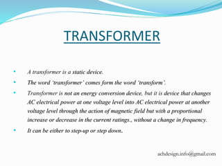
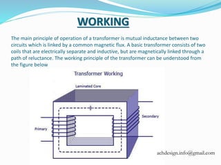
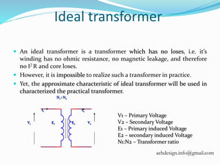
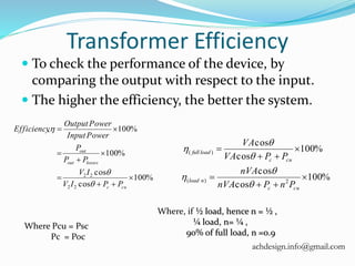
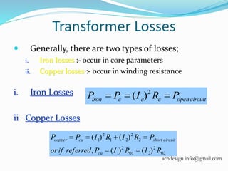
A transformer is a static device.
The word ‘transformer’ comes form the word ‘transform’.
Transformer is not an energy conversion device, but it is device that changes AC electrical power at one voltage level into AC electrical power at another voltage level through the action of magnetic field but with a proportional increase or decrease in the current ratings., without a change in frequency.
It can be either to step-up or step down.
2. TRANSFORMER
• A transformer is a static device.
• The word ‘transformer’ comes form the word ‘transform’.
• Transformer is not an energy conversion device, but it is device that changes
AC electrical power at one voltage level into AC electrical power at another
voltage level through the action of magnetic field but with a proportional
increase or decrease in the current ratings., without a change in frequency.
• It can be either to step-up or step down.
achdesign.info@gmail.com
3. The main principle of operation of a transformer is mutual inductance between two
circuits which is linked by a common magnetic flux. A basic transformer consists of two
coils that are electrically separate and inductive, but are magnetically linked through a
path of reluctance. The working principle of the transformer can be understood from
the figure below
WORKING
achdesign.info@gmail.com
4. For the simple construction of a transformer, you must
need two coils having mutual inductance and a
laminated steel core. The two coils are insulated from
each other and from the steel core. The device will also
need some suitable container for the assembled core
and windings, a medium with which the core and its
windings from its container can be insulated.
In order to insulate and to bring out the terminals of
the winding from the tank, apt bushings that are made
from either porcelain or capacitor type must be used.
achdesign.info@gmail.com
5. In all transformers that are used commercially, the core is made out of
transformer sheet steel laminations assembled to provide a continuous
magnetic path with minimum of air-gap included. The steel should
have high permeability and low hysteresis loss. For this to happen, the
steel should be made of high silicon content and must also be heat
treated. By effectively laminating the core, the eddy-current losses can
be reduced. The lamination can be done with the help of a light coat of
core plate varnish or lay an oxide layer on the surface. For a frequency
of 50 Hertz, the thickness of the lamination varies from 0.35mm to
0.5mm for a frequency of 25 Hertz.
achdesign.info@gmail.com
6. Classification of transformer
• As per phase
1. single phase
2. Three phase
• As per core
1. Core type
2. Shell type
• As per cooling system
1. Self-cooled
2. Air cooled
3. Oil cooled
achdesign.info@gmail.com
7. Transformer classified as
per core
CORE TYPE TRANSFORMER:-
In core-type transformer, the windings are given to a
considerable part of the core. The coils used for this transformer are form-wound and are of
cylindrical type. Such a type of transformer can be applicable for small sized and large sized
transformers. In the small sized type, the core will be rectangular in shape and the coils used are
cylindrical. The figure below shows the large sized type. You can see that the round or cylindrical
coils are wound in such a way as to fit over a cruciform core section. In the case of circular
cylindrical coils, they have a fair advantage of having good mechanical strength. The cylindrical
coils will have different layers and each layer will be insulated from the other with the help of
materials like paper, cloth, macerate board and so on. The general arrangement of the core-type
transformer with respect to the core is shown below. Both low-voltage (LV) and high voltage (HV)
windings are shown.
achdesign.info@gmail.com
8. The low voltage windings are placed nearer to the core as it is
the easiest to insulate. The effective core area of the
transformer can be reduced with the use of laminations and
insulation
achdesign.info@gmail.com
9. Shell-Type Transformer
In shell-type transformers the core surrounds a considerable portion of
the windings. The comparison is shown in the figure below.
The coils are form-wound but are multi layer disc type usually wound in the form of pancakes.
Paper is used to insulate the different layers of the multi-layer discs. The whole winding consists
of discs stacked with insulation spaces between the coils. These insulation spaces form the
horizontal cooling and insulating ducts. Such a transformer may have the shape of a simple
rectangle or may also have a distributed form. Both designs are shown in the figure below:
achdesign.info@gmail.com
10. A strong rigid mechanical bracing must be given to the cores and coils of the transformers. This will
help in minimizing the movement of the device and also prevents the device from getting any
insulation damage. A transformer with good bracing will not produce any humming noise during its
working and will also reduce vibration.
A special housing platform must be provided for transformers. Usually, the device is placed in tightly-
fitted sheet-metal tanks filled with special insulating oil. This oil is needed to circulate through the
device and cool the coils. It is also responsible for providing the additional insulation for the device
when it is left in the air. achdesign.info@gmail.com
11. CLASSIFICATION ON THE BASIS OF COOLING EMPLOYED
Oil filled self cooled type uses small and medium-sized distribution
transformers. The assembled windings and core of such transformers
are mounted in a welded, oil-tight steel tanks provided with a steel
cover. The tank is filled with purified, high quality insulating oil as
soon as the core is put back at its proper place. The oil helps in
transferring the heat from the core and the windings to the case from
where it is radiated out to the surroundings. For smaller sized
transformers the tanks are usually smooth surfaced, but for large size
transformers a greater heat radiation area is needed, and that too
without disturbing the cubical capacity of the tank. This is achieved by
frequently corrugating the cases. Still larger sizes are provided with
radiation or pipes.
achdesign.info@gmail.com
12. 2. Oil Filled Water Cooled Type
This type is used for much more economic construction of large
transformers, as the above told self cooled method is very expensive.
The same method is used here as well- the windings and the core are
immersed in the oil. The only difference is that a cooling coil is
mounted near the surface of the oil, through which cold water keeps
circulating. This water carries the heat from the device. This design is
usually implemented on transformers that are used in high voltage
transmission lines. The biggest advantage of such a design is that such
transformers do not require housing other than their own. This reduces
the costs by a huge amount. Another advantage is that the maintenance
and inspection of this type is only needed once or twice in a year.
achdesign.info@gmail.com
13. 3. Air Blast Type
This type is used for transformers that use voltages below
25,000 volts. The transformer is housed in a thin sheet
metal box open at both ends through which air is blown
from the bottom to the top.
achdesign.info@gmail.com
15. Three phase transformer
Normally , when three-phase is required, a single enclosure with three
primary and three secondary windings wound on a common core is all that
is required. However three single-phase transformers with the same rating
can be connected to form a three-phase bank. Since each single-phase
transformer has a primary and a secondary winding, then 3 single-phase
transformers will have the required 3 primary and 3 secondary windings and
can be connected in the field either Delta-Delta or Delta-Wye to
achieve the required three-phased transformer bank
achdesign.info@gmail.com
16. Ideal transformer
An ideal transformer is a transformer which has no loses, i.e. it’s
winding has no ohmic resistance, no magnetic leakage, and therefore
no I2 R and core loses.
However, it is impossible to realize such a transformer in practice.
Yet, the approximate characteristic of ideal transformer will be used in
characterized the practical transformer.
V1 V2
N1 : N2
E1 E2
I1 I2
V1 – Primary Voltage
V2 – Secondary Voltage
E1 – Primary induced Voltage
E2 – secondary induced Voltage
N1:N2 – Transformer ratio
achdesign.info@gmail.com
17. Transformer Efficiency
To check the performance of the device, by
comparing the output with respect to the input.
The higher the efficiency, the better the system.
%100
cos
cos
%100
%100,
22
22
cuc
lossesout
out
PPIV
IV
PP
P
PowerInput
PowerOutput
Efficiency
%100
cos
cos
%100
cos
cos
2)(
)(
cuc
nload
cuc
loadfull
PnPnVA
nVA
PPVA
VA
Where, if ½ load, hence n = ½ ,
¼ load, n= ¼ ,
90% of full load, n =0.9
Where Pcu = Psc
Pc = Poc
achdesign.info@gmail.com
18. Transformer Losses
Generally, there are two types of losses;
i. Iron losses :- occur in core parameters
ii. Copper losses :- occur in winding resistance
i. Iron Losses
ii Copper Losses
circuitopenccciron PRIPP 2
)(
02
2
201
2
1
2
2
21
2
1
)()(,
)()(
RIRIPreferredifor
PRIRIPP
cu
circuitshortcucopper
achdesign.info@gmail.com