Download as PDF, PPTX

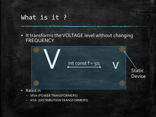
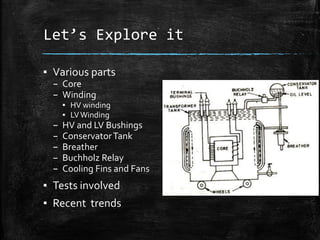
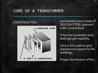
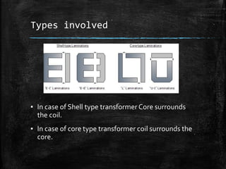
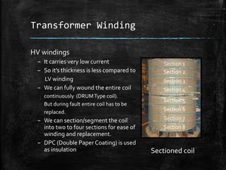
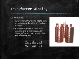
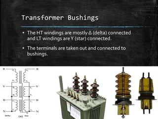
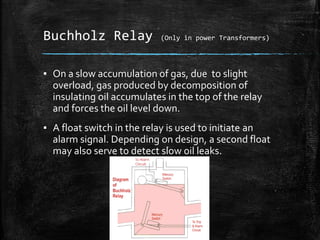
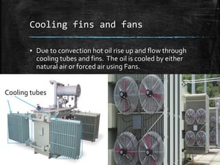
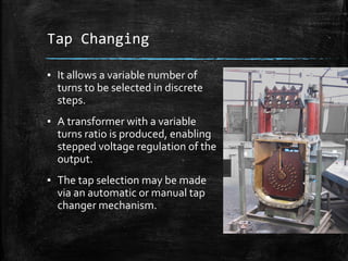
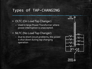


Transformer works by increasing or decreasing voltage levels without changing frequency. It has a core made of silicon steel laminations and winding coils. Key parts include the core, HV and LV windings, bushings, conservator tank, breather, and Buchholz relay. Transformer types depend on whether the core surrounds the coil or vice versa. Windings are insulated and sectioned or wound continuously. Tests ensure safety and performance. Recent trends focus on more efficient designs using improved materials.


![Transformer Repair Workshop Report [EEE]](https://cdn.slidesharecdn.com/ss_thumbnails/transformerrepairworkshopeee-140621072318-phpapp01-thumbnail.jpg?width=640&height=640&fit=bounds)


